EP0249318A1 - Handhabungsgerät - Google Patents
Handhabungsgerät Download PDFInfo
- Publication number
- EP0249318A1 EP0249318A1 EP87303556A EP87303556A EP0249318A1 EP 0249318 A1 EP0249318 A1 EP 0249318A1 EP 87303556 A EP87303556 A EP 87303556A EP 87303556 A EP87303556 A EP 87303556A EP 0249318 A1 EP0249318 A1 EP 0249318A1
- Authority
- EP
- European Patent Office
- Prior art keywords
- manipulator
- flexure members
- elongate
- members
- flexure
- Prior art date
- Legal status (The legal status is an assumption and is not a legal conclusion. Google has not performed a legal analysis and makes no representation as to the accuracy of the status listed.)
- Granted
Links
Images


Classifications
-
- B—PERFORMING OPERATIONS; TRANSPORTING
- B25—HAND TOOLS; PORTABLE POWER-DRIVEN TOOLS; MANIPULATORS
- B25J—MANIPULATORS; CHAMBERS PROVIDED WITH MANIPULATION DEVICES
- B25J18/00—Arms
- B25J18/06—Arms flexible
-
- B—PERFORMING OPERATIONS; TRANSPORTING
- B23—MACHINE TOOLS; METAL-WORKING NOT OTHERWISE PROVIDED FOR
- B23Q—DETAILS, COMPONENTS, OR ACCESSORIES FOR MACHINE TOOLS, e.g. ARRANGEMENTS FOR COPYING OR CONTROLLING; MACHINE TOOLS IN GENERAL CHARACTERISED BY THE CONSTRUCTION OF PARTICULAR DETAILS OR COMPONENTS; COMBINATIONS OR ASSOCIATIONS OF METAL-WORKING MACHINES, NOT DIRECTED TO A PARTICULAR RESULT
- B23Q1/00—Members which are comprised in the general build-up of a form of machine, particularly relatively large fixed members
- B23Q1/25—Movable or adjustable work or tool supports
- B23Q1/26—Movable or adjustable work or tool supports characterised by constructional features relating to the co-operation of relatively movable members; Means for preventing relative movement of such members
- B23Q1/34—Relative movement obtained by use of deformable elements, e.g. piezoelectric, magnetostrictive, elastic or thermally-dilatable elements
-
- B—PERFORMING OPERATIONS; TRANSPORTING
- B25—HAND TOOLS; PORTABLE POWER-DRIVEN TOOLS; MANIPULATORS
- B25J—MANIPULATORS; CHAMBERS PROVIDED WITH MANIPULATION DEVICES
- B25J9/00—Program-controlled manipulators
- B25J9/08—Program-controlled manipulators characterised by modular constructions
-
- F—MECHANICAL ENGINEERING; LIGHTING; HEATING; WEAPONS; BLASTING
- F16—ENGINEERING ELEMENTS AND UNITS; GENERAL MEASURES FOR PRODUCING AND MAINTAINING EFFECTIVE FUNCTIONING OF MACHINES OR INSTALLATIONS; THERMAL INSULATION IN GENERAL
- F16H—GEARING
- F16H21/00—Gearings comprising primarily only links or levers, with or without slides
- F16H21/46—Gearings comprising primarily only links or levers, with or without slides with movements in three dimensions [3D]
- F16H21/54—Gearings comprising primarily only links or levers, with or without slides with movements in three dimensions [3D] for conveying or interconverting oscillating or reciprocating motions
Definitions
- This invention relates to remotely controllable object manipulators of the type capable of multi-directional bending and, in some instances, other movement.
- Manipulators of the aforesaid type may be advantageously employed as, among other things, dextrous "arm” or "finger” components of industrial robots.
- a manipulator capable of only bending and/or axial movement is significantly less versatile than one also capable of twisting of rotational movement.
- Another indicia of versatility is the cost of manufacturing, servicing and using the manipulator. If the cost of a manipulator is excessive in any of the foregoing respects, its use will be restricted. The cost of a manipulator will usually be directly proportional to the number of its component parts and the complexity of its design. Design simplification and minimization of the number of components parts is therefore highly desirable.
- the components that provide structural shape and integrity to the manipulator preferably should also be usable for transmission of the forces causing its bending and other desired movements. Further benefits are obtained if the force transmitting capability of the components is a multi-directional one as opposed to being only uni-directional as is the case with the cables, cords, "tendons" and similar tension-type force transmitting components used in many object manipulators.
- Another desirable design feature which also is not present in manipulators having actuators of the aforesaid tension type, is the capability for automatic restorative or "return" movement of the manipulator back to or at least toward some predetermined nominal position following cessation of the forces causing bending or other distortive movement of it.
- U.S. Patent No. 4,489,826 discloses an object manipulator capable of extension, retraction and multi-directional bending. Such movements are produced by extension and/or retraction of rigid rod elements extending from the manipulator's base section, which contains drive means connected to the rods.
- the rods serve as supports, as well as force transmitters, and have metallic universal-type joints associated therewith for connecting them to similar rods of another manipulator unit or to an object support member.
- U.S. patents of possible relevance to the present invention are: 3,060,972, 3,227,290, 3,497,083, 4,393,728, 4,494,417 and 4,551,061.
- the object manipulators of the foregoing patents are capable of multi-directional bending. While most of them utilize cables or similar tension-type actuating elements, some also have passive self-sustaining flexure elements associated therewith: see, e.g., elements 108 of 3,060,972.
- the pneumatically actuated manipulator of patent 4,551,061 also includes passive flexure elements, designated by the numerals 61, 63 and 65, which undergo relative axial displacement during bending of the manipulator.
- the present invention provides an object manipulator, suitable for use as a robot "arm” or the like, that is highly versatile and efficient in both its operation and its design.
- Each manipulator unit is capable of multi-directional bending movement, of extension and retraction along a central axis, and also of twisting movement about such axis.
- the main body section of the manipulator unit consists of a plurality of elongate self-sustaining flexure members that extend in laterally spaced and generally parallel relationship to a central axis and each other, between base and object support sections of the manipulator.
- Drive means associated with the base section of the unit drivably engages the adjacent end portions of the flexure members and selectively imparts movements to them, causing the desired bending, extension, retraction and/or twisting of the central section of the unit.
- the drive means rotates the adjacent end portions of the flexure members about their respective central axes to effect twisting movement of the main body section of the unit.
- twisting movement ensues when the drive means axially displaces certain of the flexure members relative to other of them.
- the object support section of the manipulator includes a member having portions that pivot relative to each other in response to forces imposed thereon by the axial movements of the flexure members.
- the pivoting member preferably supports another member that maintains a stable orientation during relative pivotal movement of the sections of the first member.
- the flexure members of the manipulator may be resiliently flexible throughout their lengths and formed entirely of spring steel or similar material.
- the flexure elements may be formed of substantially rigid sections interconnected by flexible force-transmitting joints of the type containing resilient elastomeric material.
- the numeral 10 in Figures 1 and 2 of the drawings designates an object manipulator unit having means defining an elongate flexible main body section 12 interconnecting a base section 14, disposed adjacent the lower end of section 12 in the illustrative vertical orientation of unit 10, and an object support section 16 disposed adjacent and fixedly connected to the opposite outer or upper end of section 12.
- Section 16 of unit 10 is adapted to receive and support, in any suitable manner, the object that is to be remotely positioned or manipulated by the unit.
- the object may be of any desired type, such as a tool, a part to be assembled with another part, a surgical instrument or, as is indicated in Figure 3 of the drawings, another manipulator unit 10.
- Manipulation of section 16 of unit 10, and of whatever object might be supported upon such section results from controlled movement undergone by the unit's main section 12 in response to inputs from drive means 26 associated with base section 14 of the unit.
- the movements of which section 12 is capable include extension and retraction along its central longitudinal axis, twisting movement about such axis (indicated by phantom lines in Figure 1) and multi-directional lateral bending movement (indicated by phantom lines in Figure 2).
- Extension and/or retraction of section 12 of unit 10 produces translatory movement of object support section 16 along the central axis of section 12. Twisting of section 12 produces rotation of object support section 16 about the central axis of section 12. Bending of section 12 produces lateral displacement and tilting of object support section 16.
- Body section 12 of unit 10 is comprised essentially of a plurality of elongate rod-like flexure members 20 that normally extend in generally parallel relationship to each other and to the central longitudinal axis of unit 10 at substantially equally spaced locations about such axis. While there are four such rods 20 in the illustrated unit 10, a greater number might be employed. As few as three could be used without unduly limiting the motion capabilities of the unit, and some of those capabilities could be realized with only two rods.
- the upper end portions of rods 20 are fixedly secured to support section 16 of unit 10, at spaced locations adjacent its periphery. In the case of the generally rectangularly shaped support section 16 shown in Figures 1 and 2, the upper end portions of rods 20 are disposed adjacent its respective corner areas.
- rods 20 may and preferably do converge slightly toward each other and the central axis of section 16 of unit 10, from their lower end portions to their upper end portions.
- Rods 20 are so constructed as to be capable of substantial bending and/or twisting strain without permanent deformation, while at the same time being resistent to such excessive bending as would impair their ability to axially transmit compressive forces and/or motions.
- Rods 20 may be formed, as shown in Figures 1 and 2, completely of spring steel or similar material, in which case they will possess the desired resilience and flexibility throughout their entire length.
- the rods may be of the construction of the rod 20 ⁇ fragmentarily shown in Figure 5 and consisting of rigid sections 22 interconnected by resilient elastomeric-type joints 24.
- the drive means carried by base section 14 of unit 10 illustratively comprises four drive assemblies 26 associated with the lower or inner end portions of respective ones of the four rods 20.
- Each assembly is identical to that shown in Figure 4.
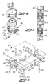
- Such assembly includes a fluid-powered piston and cylinder unit whose upstanding cylinder element 28 is mounted within base section 14 (Figs. 1 and 2) by bearings 30 for rotative movement about the cylinder's central axis.
- Such movement is imparted at desired times to cylinder 28 by a motor/clutch unit 32 having an output gear 34 meshing with a gear 36 encircling and affixed to the lower end of the cylinder.
- the rod element 38 of the piston and cylinder unit has a noncircular shape or is otherwise suitably constrained so as to rotate in unison with cylinder 28.
- the upper end of rod element 38 is fixedly secured in any suitable manner to the lower end of the therewith associated flexure rod 20 of manipulator body section 12.
- the rods 38 of each of the remaining three drive assemblies 26 are similarly affixed to the therewith associated ones of the remaining three flexure rods 20 of main body section 12 of unit 10.
- Suitable control circuitry and devices (not shown), which may include a digital computer or the like, control and coordinate the operation of drive assemblies 26 to cause main body section 12 of unit 10 to undergo movements of the desired types and extents.
- the rods 38 of all four drive assemblies 26 are caused to undergo simultaneous and equal extension or retraction.
- Leftward bending movement of main body section 12, such as illustrated in Figure 2 ensues when drive assemblies 26 effect retraction of flexure rods 20a, 20b relative to the remaining flexure rods 20c, 20d, and/or effect extension of rods 20c, 20d relative to rods 20a, 20b.
- Figure 1 illustrates counterclockwise rotation of object support section 16 through an angle of approximately 45°, the direction and extent (within, of course, maximum limits) of rotation are dependent upon the direction and extent of the rotation imparted to the lower end portions of rods 20 by drive assemblies 26.
- Object support section 16 of unit 10 would similarly tend to undergo rotative movement, such as described above, if two of the rod elements 20 at diagonally opposite corner areas of section 16 were simultaneously extended and the remaining two rod elements 20 were either simultaneously retracted or were not driven at all.
- significant actual rotative movement of section 16 in response to the forces imposed thereon in the foregoing manner would transpire only if significant relative movement could occur between different portions of section 16, and also only if the lower end portions of rods 20 were free to rotate about their respective longitudinal axes.
- the later condition can be readily met simply by either eliminating the rotation-producing components 32, 34, 36 of drive assemblies 26 ( Figure 4) or by disengagement of the clutches of components 32.
- Support 16 ⁇ includes a platform 40 having two sections 40 ⁇ , 40 ⁇ that are pivotably movable relative to each other about the axis of an elongate shaft or bearing 42 extending transversely through the sections and maintained in association therewith by collar elements 43.
- Two of the rods 20 of manipulator 10, illustratively rods 20b and 20c, have their upper ends affixed to corner areas of platform section 40 ⁇ while the remaining two rods 20a, 20d are affixed to corner areas of the other platform section 40 ⁇ .
- support section 16 ⁇ of unit 10 preferably is further provided with a second platform 44 that overlies platform 40, and is so connected to it as to remain stable while undergoing rotative movement in unison with platform 40 about the axis of body section 12.
- the means innerconnecting platforms 40, 44 incluives flexible frame means 46, and a pair of rigid extensions 48, 48 ⁇ that extend upwardly from opposite ends of shaft 42 and are fixedly connected to the undersurface of platform 44.
- Frame 46 supplements the stable supportive connection provided by elements 48, 48 ⁇ . It includes a rigid link 54 having one end connected by an elastomeric bearing 56 to a rigid link 58 affixed to an end of section 40 ⁇ of lower platform 40, and having its opposite end connected by an elastomeric bearing 60 to a rigid link 62 fixed to the corresponding end of section 40 ⁇ of platform 40.
- An upstanding rigid link 64 has its lower end portion connected by elastomeric bearing 66 to the center of link 54, and has its upper end portion connected by an elastomeric bearing 68 to upper platform 44 at a location adjacent one end of a platform center line extending normal to a vertical plane containing the axis of shaft 42.
- Identical link and bearing components designated in the drawings by the same reference numerals with the addition of a prime designation, similarly interconnect the opposite ends of lower platform sections 40 ⁇ , 40 ⁇ with upper platform 44.
- Figure 3 shows, in schematic form, a sinuous array of four serially connected units 10.
- the units are independently but cooperatively driven.
- the base of all but the first or lowermost unit is affixed to the object support section of the preceeding unit, and the object supporting section of the final unit carries a gripper 70 holding an article or tool 72.
- a greater or lesser number of units 10 might be employed in a similar array, and that the same might be caused to assume an almost limitless number of sinuous or other configurations and orientations due to each unit's capability for twisting movement in addition to bending and extension/ retraction.
- Figure 8 shows a resiliently flexible type of interconnection that may optionally be provided between flexure rods 20 of unit 10 intermediate the length of such rods.
- the connection illustratively consists of an elastically constrictive cable 74 that extends through and between eyelets 76 upon rods 20.
- elastically constrictive cable 74 that extends through and between eyelets 76 upon rods 20.
- Such interconnection assists in maintaining rods 20 in substantially parallel relationship to each other during bending thereof under substantial loads, and therefore enhances the ability of unit 10 to sustain such loads without buckling of the rods.
- Cable 74 is of course sufficiently flexible as to not impede relative movement of rods 20 along or about their longitudinal axes.
Landscapes
- Engineering & Computer Science (AREA)
- Mechanical Engineering (AREA)
- General Engineering & Computer Science (AREA)
- Robotics (AREA)
- Manipulator (AREA)
Applications Claiming Priority (2)
| Application Number | Priority Date | Filing Date | Title |
|---|---|---|---|
| US06/872,493 US4765795A (en) | 1986-06-10 | 1986-06-10 | Object manipulator |
| US872493 | 1992-04-23 |
Publications (2)
| Publication Number | Publication Date |
|---|---|
| EP0249318A1 true EP0249318A1 (de) | 1987-12-16 |
| EP0249318B1 EP0249318B1 (de) | 1989-11-23 |
Family
ID=25359673
Family Applications (1)
| Application Number | Title | Priority Date | Filing Date |
|---|---|---|---|
| EP87303556A Expired EP0249318B1 (de) | 1986-06-10 | 1987-04-23 | Handhabungsgerät |
Country Status (4)
| Country | Link |
|---|---|
| US (1) | US4765795A (de) |
| EP (1) | EP0249318B1 (de) |
| JP (1) | JPS62292385A (de) |
| DE (1) | DE3761014D1 (de) |
Cited By (6)
| Publication number | Priority date | Publication date | Assignee | Title |
|---|---|---|---|---|
| US5816769A (en) * | 1995-11-07 | 1998-10-06 | Siemens Aktiengesellschaft | Flexible manipulator |
| WO2008046566A1 (de) * | 2006-10-13 | 2008-04-24 | Robotics Technology Leaders Gmbh | Wurmförmiger mechanismus |
| DE102009015977A1 (de) * | 2009-03-26 | 2010-09-30 | Festo Ag & Co. Kg | Antriebsvorrichtung |
| CN102069392A (zh) * | 2011-02-15 | 2011-05-25 | 上海工程技术大学 | 用于虚轴机床和机器人的二转动自由度并联机构 |
| US20150141756A1 (en) * | 2012-05-12 | 2015-05-21 | Massachusetts Institute Of Technology | Continuum style manipulator actuated with phase change media |
| CN110253556A (zh) * | 2019-07-03 | 2019-09-20 | 哈工大机器人(合肥)国际创新研究院 | 一种新型仿生人体前臂扭转机构及其机器人 |
Families Citing this family (30)
| Publication number | Priority date | Publication date | Assignee | Title |
|---|---|---|---|---|
| JPH0192390U (de) * | 1987-12-10 | 1989-06-16 | ||
| US4921393A (en) * | 1988-03-09 | 1990-05-01 | Sri International | Articulatable structure with adjustable end-point compliance |
| FR2628670B1 (fr) * | 1988-03-21 | 1990-08-17 | Inst Nat Rech Inf Automat | Dispositif articule, notamment utilisable dans le domaine de la robotique |
| US4843921A (en) * | 1988-04-18 | 1989-07-04 | Kremer Stephen R | Twisted cord actuator |
| US6566834B1 (en) * | 1999-09-28 | 2003-05-20 | The United States Of America As Represented By The Secretary Of Commerce | Modular suspended manipulator |
| FR2814216B1 (fr) * | 2000-09-18 | 2002-12-20 | Snecma Moteurs | Dispositif d'orientation et systeme d'orientation embarque |
| DE10110310B4 (de) * | 2001-03-03 | 2013-08-08 | MOD Produktions GmbH | Manipulator und Verfahren zum Betrieb eines Manipulators im Submikro-Bereich |
| US6865011B2 (en) * | 2002-07-30 | 2005-03-08 | The University Of British Columbia | Self-stabilized electrophoretically frustrated total internal reflection display |
| US20060156851A1 (en) * | 2004-12-02 | 2006-07-20 | Jacobsen Stephen C | Mechanical serpentine device |
| US20080257096A1 (en) * | 2005-04-01 | 2008-10-23 | Zhenqi Zhu | Flexible Parallel Manipulator For Nano-, Meso- or Macro-Positioning With Multi-Degrees of Freedom |
| JP5520048B2 (ja) | 2006-11-13 | 2014-06-11 | レイセオン カンパニー | 蛇行型ロボット式無限軌道車 |
| ATE522431T1 (de) | 2006-11-13 | 2011-09-15 | Raytheon Co | Raupenroboter mit kette und beweglichem arm |
| US20080136254A1 (en) | 2006-11-13 | 2008-06-12 | Jacobsen Stephen C | Versatile endless track for lightweight mobile robots |
| US8002365B2 (en) | 2006-11-13 | 2011-08-23 | Raytheon Company | Conformable track assembly for a robotic crawler |
| EP2144659A1 (de) * | 2007-05-07 | 2010-01-20 | Raytheon Sarcos, LLC | Verfahren zur herstellung einer komplexen struktur |
| US8571711B2 (en) | 2007-07-10 | 2013-10-29 | Raytheon Company | Modular robotic crawler |
| US8392036B2 (en) | 2009-01-08 | 2013-03-05 | Raytheon Company | Point and go navigation system and method |
| US8935014B2 (en) | 2009-06-11 | 2015-01-13 | Sarcos, Lc | Method and system for deploying a surveillance network |
| US8317555B2 (en) | 2009-06-11 | 2012-11-27 | Raytheon Company | Amphibious robotic crawler |
| JP2012096337A (ja) * | 2010-11-05 | 2012-05-24 | Ryutai Servo:Kk | 剛性を有する複数の弾性ワイヤーを用いたパラレルメカニズム |
| KR101164378B1 (ko) * | 2011-06-07 | 2012-07-09 | 양국진 | 병렬형 머니퓰레이터 |
| US8393422B1 (en) | 2012-05-25 | 2013-03-12 | Raytheon Company | Serpentine robotic crawler |
| US9031698B2 (en) | 2012-10-31 | 2015-05-12 | Sarcos Lc | Serpentine robotic crawler |
| US9409292B2 (en) | 2013-09-13 | 2016-08-09 | Sarcos Lc | Serpentine robotic crawler for performing dexterous operations |
| US9566711B2 (en) | 2014-03-04 | 2017-02-14 | Sarcos Lc | Coordinated robotic control |
| JPWO2016063348A1 (ja) | 2014-10-21 | 2017-09-28 | オリンパス株式会社 | 湾曲機構および軟性医療器具 |
| RU178868U1 (ru) * | 2016-12-05 | 2018-04-20 | Общество с ограниченной ответственностью "Волговятские мастерские точной механики" (ООО "Волговятскмеханика") | Секционный гибкий манипулятор |
| CN112405590B (zh) * | 2020-11-06 | 2021-12-31 | 北京理工大学 | 一种新型手指分体、机械手及其抓取方法 |
| US12311550B2 (en) | 2020-12-31 | 2025-05-27 | Sarcos Corp. | Smart control system for a robotic device |
| JP2024175642A (ja) * | 2023-06-06 | 2024-12-18 | ライオンパワー株式会社 | パラレルリンクマニピュレータ |
Citations (2)
| Publication number | Priority date | Publication date | Assignee | Title |
|---|---|---|---|---|
| US3266059A (en) * | 1963-06-19 | 1966-08-16 | North American Aviation Inc | Prestressed flexible joint for mechanical arms and the like |
| DE2732559A1 (de) * | 1976-07-22 | 1978-01-26 | Du Pont | Kurvensystem |
Family Cites Families (23)
| Publication number | Priority date | Publication date | Assignee | Title |
|---|---|---|---|---|
| US1001603A (en) * | 1908-02-17 | 1911-08-29 | Charles J Aschauer | Pole. |
| US2027386A (en) * | 1932-12-03 | 1936-01-14 | Krummer Adolf | System for moving bodies towards and away from each other |
| DE1208566B (de) * | 1956-02-23 | 1966-01-05 | Maria Reich Geb Hellbruegge | Elastische Wellenkupplung |
| US3060972A (en) * | 1957-08-22 | 1962-10-30 | Bausch & Lomb | Flexible tube structures |
| US3227290A (en) * | 1963-01-11 | 1966-01-04 | Jerome H Lemelson | Article handling apparatus |
| US3284964A (en) * | 1964-03-26 | 1966-11-15 | Saito Norio | Flexible beam structures |
| US3497083A (en) * | 1968-05-10 | 1970-02-24 | Us Navy | Tensor arm manipulator |
| US3864983A (en) * | 1972-09-15 | 1975-02-11 | Stephen C Jacobsen | Rotary-to-linear and linear-to-rotary motion converters |
| NO137351C (no) * | 1976-01-30 | 1978-02-22 | Trallfa Nils Underhaug As | B¦yelig robotarm. |
| SU676441A1 (ru) * | 1977-05-24 | 1979-07-30 | Всесоюзный Проектно-Технологический Институт Тяжелого Машиностроения | Механизм ориентировани схвата манипул тора |
| US4176522A (en) * | 1978-01-20 | 1979-12-04 | Mark Holtzapple | Torque monitor |
| FR2462607A2 (fr) * | 1978-09-20 | 1981-02-13 | Ass Ouvriers Instr Precision | Articulation pour bras de manipulateur |
| US4494417A (en) * | 1979-03-16 | 1985-01-22 | Robotgruppen Hb | Flexible arm, particularly a robot arm |
| SE419421B (sv) * | 1979-03-16 | 1981-08-03 | Ove Larson | Bojlig arm i synnerhet robotarm |
| GB2083795B (en) * | 1980-09-13 | 1984-01-25 | Marconi Co Ltd | Manipulator mechanisms |
| SU1007959A1 (ru) * | 1981-07-17 | 1983-03-30 | Кишиневский политехнический институт им.С.Лазо | Рука манипул тора |
| US4489826A (en) * | 1982-02-05 | 1984-12-25 | Philip Dubson | Adjustable apparatus |
| SE436175B (sv) * | 1982-07-05 | 1984-11-19 | Robotgruppen Hb | Anordning for vridstyv forbindelse av i en robotarm eller liknande ingaende element |
| PT77732B (en) * | 1982-12-16 | 1986-03-27 | Cyber Robotics Ltd | Robotic limb |
| GB8303694D0 (en) * | 1983-02-10 | 1983-03-16 | Atomic Energy Authority Uk | Manipulators |
| US4551061A (en) * | 1983-04-18 | 1985-11-05 | Olenick Ralph W | Flexible, extensible robot arm |
| US4557097A (en) * | 1983-09-08 | 1985-12-10 | The United States Of America As Represented By The Administrator Of The National Aeronautics And Space Administration | Sequentially deployable maneuverable tetrahedral beam |
| SU1222538A1 (ru) * | 1984-06-15 | 1986-04-07 | Институт Машиноведения Им.А.А.Благонравова | @ -Координатный пространственный механизм (его варианты) |
-
1986
- 1986-06-10 US US06/872,493 patent/US4765795A/en not_active Expired - Fee Related
-
1987
- 1987-04-23 DE DE8787303556T patent/DE3761014D1/de not_active Expired
- 1987-04-23 EP EP87303556A patent/EP0249318B1/de not_active Expired
- 1987-06-08 JP JP62141654A patent/JPS62292385A/ja active Pending
Patent Citations (2)
| Publication number | Priority date | Publication date | Assignee | Title |
|---|---|---|---|---|
| US3266059A (en) * | 1963-06-19 | 1966-08-16 | North American Aviation Inc | Prestressed flexible joint for mechanical arms and the like |
| DE2732559A1 (de) * | 1976-07-22 | 1978-01-26 | Du Pont | Kurvensystem |
Cited By (10)
| Publication number | Priority date | Publication date | Assignee | Title |
|---|---|---|---|---|
| US5816769A (en) * | 1995-11-07 | 1998-10-06 | Siemens Aktiengesellschaft | Flexible manipulator |
| WO2008046566A1 (de) * | 2006-10-13 | 2008-04-24 | Robotics Technology Leaders Gmbh | Wurmförmiger mechanismus |
| US8201473B2 (en) | 2006-10-13 | 2012-06-19 | Robotics Technology Leaders Gmbh | Worm-like mechanism |
| DE102009015977A1 (de) * | 2009-03-26 | 2010-09-30 | Festo Ag & Co. Kg | Antriebsvorrichtung |
| CN102069392A (zh) * | 2011-02-15 | 2011-05-25 | 上海工程技术大学 | 用于虚轴机床和机器人的二转动自由度并联机构 |
| CN102069392B (zh) * | 2011-02-15 | 2012-08-08 | 上海工程技术大学 | 用于虚轴机床和机器人的二转动自由度并联机构 |
| US20150141756A1 (en) * | 2012-05-12 | 2015-05-21 | Massachusetts Institute Of Technology | Continuum style manipulator actuated with phase change media |
| US9713873B2 (en) * | 2012-05-12 | 2017-07-25 | Massachusetts Institute Of Technology | Continuum style manipulator actuated with phase change media |
| CN110253556A (zh) * | 2019-07-03 | 2019-09-20 | 哈工大机器人(合肥)国际创新研究院 | 一种新型仿生人体前臂扭转机构及其机器人 |
| CN110253556B (zh) * | 2019-07-03 | 2020-12-15 | 合肥哈工力训智能科技有限公司 | 一种新型仿生人体前臂扭转机构及其机器人 |
Also Published As
| Publication number | Publication date |
|---|---|
| JPS62292385A (ja) | 1987-12-19 |
| DE3761014D1 (en) | 1989-12-28 |
| US4765795A (en) | 1988-08-23 |
| EP0249318B1 (de) | 1989-11-23 |
Similar Documents
| Publication | Publication Date | Title |
|---|---|---|
| EP0249318B1 (de) | Handhabungsgerät | |
| JP3356706B2 (ja) | 機械的に巧みな握持を行なう方法 | |
| US5673595A (en) | Four degree-of-freedom manipulator | |
| US5114300A (en) | Robotic apparatus | |
| US6339969B1 (en) | Three-degree-of-freedom parallel planar manipulator | |
| US8498741B2 (en) | Dexterous humanoid robotic wrist | |
| KR102246778B1 (ko) | 손가락 기구 및 이를 포함하는 로봇 핸드 | |
| US4921393A (en) | Articulatable structure with adjustable end-point compliance | |
| EP1863734B1 (de) | Parallelroboter | |
| US8511964B2 (en) | Humanoid robot | |
| US8549952B2 (en) | Robot and method for controlling the robot | |
| US5052736A (en) | Modular dexterous hand | |
| EP1137516B1 (de) | Manipulator mit einer parallelogrammstruktur mit einer federvorrichtung, die eine zugkraft ausübt | |
| US20100300230A1 (en) | Device for Movement Between an Input Member and an Output Member | |
| EP1084802A2 (de) | Parallelroboter mit vier Freiheitsgraden | |
| JPS63150178A (ja) | マニピュレータ | |
| CN114102665B (zh) | 基于折纸结构的模块化多铰链可伸缩刚柔耦合空间机械臂 | |
| JP2003535711A (ja) | 2つのパラレルブランチを有する制御アーム | |
| CN113334422A (zh) | 机器人关节结构及包含其的机械手 | |
| JP7182041B2 (ja) | ロボットハンド | |
| Koganezawa et al. | Antagonistic control of multi-DOF joint by using the actuator with non-linear elasticity | |
| JP2001121460A (ja) | ロボット用パラレルリンク機構 | |
| CN115476331B (zh) | 机械手以及主从随动设备 | |
| EP0540197A1 (de) | Aktuator eines Handeingabegeräts | |
| JP7828196B2 (ja) | ロボットアーム、エンドエフェクタ、ロボットアームの駆動方法、ロボットアームの駆動プログラム |
Legal Events
| Date | Code | Title | Description |
|---|---|---|---|
| PUAI | Public reference made under article 153(3) epc to a published international application that has entered the european phase |
Free format text: ORIGINAL CODE: 0009012 |
|
| 17P | Request for examination filed |
Effective date: 19870508 |
|
| AK | Designated contracting states |
Kind code of ref document: A1 Designated state(s): BE DE FR GB IT NL SE |
|
| R17P | Request for examination filed (corrected) |
Effective date: 19880603 |
|
| 17Q | First examination report despatched |
Effective date: 19890313 |
|
| GRAA | (expected) grant |
Free format text: ORIGINAL CODE: 0009210 |
|
| AK | Designated contracting states |
Kind code of ref document: B1 Designated state(s): BE DE FR GB IT NL SE |
|
| PG25 | Lapsed in a contracting state [announced via postgrant information from national office to epo] |
Ref country code: IT Free format text: LAPSE BECAUSE OF FAILURE TO SUBMIT A TRANSLATION OF THE DESCRIPTION OR TO PAY THE FEE WITHIN THE PRE;WARNING: LAPSES OF ITALIAN PATENTS WITH EFFECTIVE DATE BEFORE 2007 MAY HAVE OCCURRED AT ANY TIME BEFORE 2007. THE CORRECT EFFECTIVE DATE MAY BE DIFFERENT FROM THE ONE RECORDED.SCRIBED TIME-LIMIT Effective date: 19891123 Ref country code: SE Effective date: 19891123 Ref country code: NL Effective date: 19891123 Ref country code: BE Effective date: 19891123 |
|
| REF | Corresponds to: |
Ref document number: 3761014 Country of ref document: DE Date of ref document: 19891228 |
|
| ET | Fr: translation filed | ||
| NLV1 | Nl: lapsed or annulled due to failure to fulfill the requirements of art. 29p and 29m of the patents act | ||
| PLBE | No opposition filed within time limit |
Free format text: ORIGINAL CODE: 0009261 |
|
| STAA | Information on the status of an ep patent application or granted ep patent |
Free format text: STATUS: NO OPPOSITION FILED WITHIN TIME LIMIT |
|
| 26N | No opposition filed | ||
| PG25 | Lapsed in a contracting state [announced via postgrant information from national office to epo] |
Ref country code: FR Effective date: 19901228 |
|
| PG25 | Lapsed in a contracting state [announced via postgrant information from national office to epo] |
Ref country code: DE Effective date: 19910101 |
|
| REG | Reference to a national code |
Ref country code: FR Ref legal event code: ST |
|
| PG25 | Lapsed in a contracting state [announced via postgrant information from national office to epo] |
Ref country code: GB Effective date: 19910423 |
|
| GBPC | Gb: european patent ceased through non-payment of renewal fee |