EP0249351B1 - Commande de manette des gaz - Google Patents
Commande de manette des gaz Download PDFInfo
- Publication number
- EP0249351B1 EP0249351B1 EP87304481A EP87304481A EP0249351B1 EP 0249351 B1 EP0249351 B1 EP 0249351B1 EP 87304481 A EP87304481 A EP 87304481A EP 87304481 A EP87304481 A EP 87304481A EP 0249351 B1 EP0249351 B1 EP 0249351B1
- Authority
- EP
- European Patent Office
- Prior art keywords
- throttle
- control
- combining
- block
- linkage means
- Prior art date
- Legal status (The legal status is an assumption and is not a legal conclusion. Google has not performed a legal analysis and makes no representation as to the accuracy of the status listed.)
- Expired - Lifetime
Links
Images

Classifications
-
- G—PHYSICS
- G05—CONTROLLING; REGULATING
- G05G—CONTROL DEVICES OR SYSTEMS INSOFAR AS CHARACTERISED BY MECHANICAL FEATURES ONLY
- G05G11/00—Manually-actuated control mechanisms provided with two or more controlling members co-operating with one single controlled member
-
- B—PERFORMING OPERATIONS; TRANSPORTING
- B60—VEHICLES IN GENERAL
- B60K—ARRANGEMENT OR MOUNTING OF PROPULSION UNITS OR OF TRANSMISSIONS IN VEHICLES; ARRANGEMENT OR MOUNTING OF PLURAL DIVERSE PRIME-MOVERS IN VEHICLES; AUXILIARY DRIVES FOR VEHICLES; INSTRUMENTATION OR DASHBOARDS FOR VEHICLES; ARRANGEMENTS IN CONNECTION WITH COOLING, AIR INTAKE, GAS EXHAUST OR FUEL SUPPLY OF PROPULSION UNITS IN VEHICLES
- B60K26/00—Arrangement or mounting of propulsion-unit control devices in vehicles
- B60K26/02—Arrangement or mounting of propulsion-unit control devices in vehicles of initiating means or elements
-
- F—MECHANICAL ENGINEERING; LIGHTING; HEATING; WEAPONS; BLASTING
- F16—ENGINEERING ELEMENTS AND UNITS; GENERAL MEASURES FOR PRODUCING AND MAINTAINING EFFECTIVE FUNCTIONING OF MACHINES OR INSTALLATIONS; THERMAL INSULATION IN GENERAL
- F16C—SHAFTS; FLEXIBLE SHAFTS; ELEMENTS OR CRANKSHAFT MECHANISMS; ROTARY BODIES OTHER THAN GEARING ELEMENTS; BEARINGS
- F16C1/00—Flexible shafts; Mechanical means for transmitting movement in a flexible sheathing
- F16C1/10—Means for transmitting linear movement in a flexible sheathing, e.g. "Bowden-mechanisms"
- F16C1/101—Intermediate connectors for joining portions of split flexible shafts and/or sheathings
-
- F—MECHANICAL ENGINEERING; LIGHTING; HEATING; WEAPONS; BLASTING
- F16—ENGINEERING ELEMENTS AND UNITS; GENERAL MEASURES FOR PRODUCING AND MAINTAINING EFFECTIVE FUNCTIONING OF MACHINES OR INSTALLATIONS; THERMAL INSULATION IN GENERAL
- F16C—SHAFTS; FLEXIBLE SHAFTS; ELEMENTS OR CRANKSHAFT MECHANISMS; ROTARY BODIES OTHER THAN GEARING ELEMENTS; BEARINGS
- F16C1/00—Flexible shafts; Mechanical means for transmitting movement in a flexible sheathing
- F16C1/10—Means for transmitting linear movement in a flexible sheathing, e.g. "Bowden-mechanisms"
- F16C1/106—Plurality of transmitting means, e.g. two or more parallel "Bowden cables"
-
- F—MECHANICAL ENGINEERING; LIGHTING; HEATING; WEAPONS; BLASTING
- F16—ENGINEERING ELEMENTS AND UNITS; GENERAL MEASURES FOR PRODUCING AND MAINTAINING EFFECTIVE FUNCTIONING OF MACHINES OR INSTALLATIONS; THERMAL INSULATION IN GENERAL
- F16C—SHAFTS; FLEXIBLE SHAFTS; ELEMENTS OR CRANKSHAFT MECHANISMS; ROTARY BODIES OTHER THAN GEARING ELEMENTS; BEARINGS
- F16C2326/00—Articles relating to transporting
- F16C2326/01—Parts of vehicles in general
-
- Y—GENERAL TAGGING OF NEW TECHNOLOGICAL DEVELOPMENTS; GENERAL TAGGING OF CROSS-SECTIONAL TECHNOLOGIES SPANNING OVER SEVERAL SECTIONS OF THE IPC; TECHNICAL SUBJECTS COVERED BY FORMER USPC CROSS-REFERENCE ART COLLECTIONS [XRACs] AND DIGESTS
- Y10—TECHNICAL SUBJECTS COVERED BY FORMER USPC
- Y10T—TECHNICAL SUBJECTS COVERED BY FORMER US CLASSIFICATION
- Y10T74/00—Machine element or mechanism
- Y10T74/20—Control lever and linkage systems
- Y10T74/20012—Multiple controlled elements
- Y10T74/20201—Control moves in two planes
-
- Y—GENERAL TAGGING OF NEW TECHNOLOGICAL DEVELOPMENTS; GENERAL TAGGING OF CROSS-SECTIONAL TECHNOLOGIES SPANNING OVER SEVERAL SECTIONS OF THE IPC; TECHNICAL SUBJECTS COVERED BY FORMER USPC CROSS-REFERENCE ART COLLECTIONS [XRACs] AND DIGESTS
- Y10—TECHNICAL SUBJECTS COVERED BY FORMER USPC
- Y10T—TECHNICAL SUBJECTS COVERED BY FORMER US CLASSIFICATION
- Y10T74/00—Machine element or mechanism
- Y10T74/20—Control lever and linkage systems
- Y10T74/20207—Multiple controlling elements for single controlled element
- Y10T74/20213—Interconnected
-
- Y—GENERAL TAGGING OF NEW TECHNOLOGICAL DEVELOPMENTS; GENERAL TAGGING OF CROSS-SECTIONAL TECHNOLOGIES SPANNING OVER SEVERAL SECTIONS OF THE IPC; TECHNICAL SUBJECTS COVERED BY FORMER USPC CROSS-REFERENCE ART COLLECTIONS [XRACs] AND DIGESTS
- Y10—TECHNICAL SUBJECTS COVERED BY FORMER USPC
- Y10T—TECHNICAL SUBJECTS COVERED BY FORMER US CLASSIFICATION
- Y10T74/00—Machine element or mechanism
- Y10T74/20—Control lever and linkage systems
- Y10T74/20396—Hand operated
- Y10T74/20402—Flexible transmitter [e.g., Bowden cable]
- Y10T74/2042—Flexible transmitter [e.g., Bowden cable] and hand operator
Definitions
- This invention relates to throttle controls and in particular to combined hand and foot controls which allow the position of a throttle member of a prime mover to be adjusted by both an operator's hand and foot.
- Such combined hand and foot controls are common on agricultural tractors to adjust the position of a throttle lever on a diesel engine fuel injection pump but are frequently relatively complex in construction and because of a tendency to use rigid links often require to be tailored for each particular tractor in a given tractor manufacturers' range.
- a throttle control for a prime mover comprising a prime mover throttle member, a hand control, a foot control, a combining device including a support member and a combining member movable relative to the support member in first and second opposite directions, first linkage means connecting the combining member with the throttle member so that movement of the combining member in said first direction moves the throttle member towards a fully open position, bias means acting to bias the throttle member towards an idle position and hence bias said combining member in said second direction via the first linkage means, second linkage means connecting the foot control and combining member for movement of the combining member in said first direction, and third linkage means connecting the hand control with the combining member via a connection capable of moving the combining member in said first direction only and allowing movement of the combining member in said first and second directions relative to the third linkage means, the arrangement being such that any throttle member position set by the hand control can be increased using the foot control by said second linkage means moving the combining member in said first direction relative to said third linkage means, the arrangement being such that any
- each linkage means includes a Bowden cable to permit easy installation of the Control on a tractor.
- the support member may conveniently comprise a housing within which a combining member in the form of slidable block is supported.
- each cable When employing linkage means including a Bowden cable the outer of each cable may be held captive by the housing and the inner of each cable connected with the slidable block.
- the slidable block may be provided with three slots which extend end to end of the block in directions parallel to said first and second directions, each slot being arranged to receive a respective Bowden cable inner loosely slidable therein and each inner being connected with the block by abutment of a nipple thereon with a respective end face of the block to transmit motion to the block by tension of the inner.
- this shows a combined hand and foot control arrangement for a throttle member in the form of a throttle lever 10 of the tractor diesel engine fuel injection pump 11.
- the control arrangement includes a hand control lever 12 and a throttle pedal 13 which are both connected with a combining device 14 via Bowden cables 15 and 16 respectively.
- the combining device is in turn itself connected by a further Bowden cable 17 with the throttle lever 10.
- the hand control lever 12 is supported on a shaft 12a for pivoting about an axis A-A by a lower bracket 18 and an upper bearing support 19 provided as part of the vehicle instrument panel.
- the end 15a of the inner of Bowden cable 15 is connected with an arm 20 which is supported from a boss 21 on the lower end of shaft 12a.
- a friction device is provided to hold the hand lever in the position set by the tractor operator. This can conveniently be provided by the arrangement shown in Figure 2 in which friction material 22 on the bottom of boss 21 is clamped against support bracket 18 by a compression spring 23 which is held captive on the lower end of shaft 12a by a washer 24 and nut 25.
- the throttle pedal 13 is mounted for pivoting about an axis B-B just below the tractor cab floor or foot- step, part of which is shown at 26.
- the pedal is provided with a stop 27 which abuts the underside of floor 26 to limit the downward movement of pedal 13.
- the end 16a of the inner of Bowden cable 16 is connected with pedal 13 via an arm 28 and a spring 29 acts between the arm 28 and a fixed point 30 on the tractor to maintain the Bowden cable end 16a tensioned and also to prevent vibration of the throttle pedal arrangement.
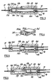
- the combining device 14 comprises two housing halves 14a and 14b of plastics material which are bolted together at 31. These bolts 31 also serve to secure the combining device to a support bracket 32 which is mounted on any convenient part of the tractor.
- Figure 3 shows the internal details of the combining device with the upper part 14a removed.
- a channel 33 is defined in which a combining member 34 in the form of a plastics block is slidable. This block is shown in greater detail in Figure 4.
- the block includes three longitudinally extending slots 35, 36 and 37 which are arranged to receive the ends 15b, 16b, 17b of the inners Bowden cables 15, 16 and 17 respectively.
- the nipples 15c and 16c of cables 15 and 16 are partially recieved in recesses 35a and 36a provided in block 34.
- the nipple 17c of cable 17 is received in a corresponding recess in the opposite end of block 34.
- the outers of cables 15, 16 and 17 are held captive within the housing halves by engagement of end ferrules 15d, 16d and 17d in recesses 14c and 14d in the housing halves.
- Figure 3 shows the combining member 34 in its minimum or idling speed position corresponding to the position of the hand control 12 and pedal 13 of Figure I. In this position the throttle lever is biased by spring 38 into its closed or idle position shown in Figure I.
- the present invention therefore provides a simple, low cost and efficient arrangement for combining hand and foot throttle controls which, due to its use of flexible Bowden cables, is particularly easy to install on a variety of different machines, since the cables can easily be routed to the throttle lever from the hand and foot controls by the most convenient route.
Landscapes
- Engineering & Computer Science (AREA)
- General Engineering & Computer Science (AREA)
- Mechanical Engineering (AREA)
- Oral & Maxillofacial Surgery (AREA)
- Health & Medical Sciences (AREA)
- Automation & Control Theory (AREA)
- Physics & Mathematics (AREA)
- General Physics & Mathematics (AREA)
- Chemical & Material Sciences (AREA)
- Combustion & Propulsion (AREA)
- Transportation (AREA)
- Control Of Throttle Valves Provided In The Intake System Or In The Exhaust System (AREA)
- Auxiliary Drives, Propulsion Controls, And Safety Devices (AREA)
- Gloves (AREA)
Claims (6)
Applications Claiming Priority (2)
| Application Number | Priority Date | Filing Date | Title |
|---|---|---|---|
| GB8613915 | 1986-06-07 | ||
| GB8613915A GB2191272B (en) | 1986-06-07 | 1986-06-07 | Throttle controls |
Publications (3)
| Publication Number | Publication Date |
|---|---|
| EP0249351A2 EP0249351A2 (fr) | 1987-12-16 |
| EP0249351A3 EP0249351A3 (en) | 1989-01-25 |
| EP0249351B1 true EP0249351B1 (fr) | 1990-07-18 |
Family
ID=10599148
Family Applications (1)
| Application Number | Title | Priority Date | Filing Date |
|---|---|---|---|
| EP87304481A Expired - Lifetime EP0249351B1 (fr) | 1986-06-07 | 1987-05-20 | Commande de manette des gaz |
Country Status (7)
| Country | Link |
|---|---|
| US (1) | US4811620A (fr) |
| EP (1) | EP0249351B1 (fr) |
| BR (1) | BR8703379A (fr) |
| CA (1) | CA1279236C (fr) |
| DE (1) | DE3763759D1 (fr) |
| GB (1) | GB2191272B (fr) |
| MX (1) | MX168501B (fr) |
Families Citing this family (24)
| Publication number | Priority date | Publication date | Assignee | Title |
|---|---|---|---|---|
| US4917418A (en) * | 1988-12-12 | 1990-04-17 | Babcock Industries Inc. | Fuel filler door release system |
| US4998758A (en) * | 1990-04-10 | 1991-03-12 | General Motors Corporation | Low effort remote latch actuator |
| US5094322A (en) * | 1990-05-21 | 1992-03-10 | Casillas Linda M | Double lever braking system |
| DE4039871A1 (de) * | 1990-12-13 | 1992-06-17 | Dautel Emil Gmbh | Transportfahrzeug mit wechselaufbau |
| US5197347A (en) * | 1992-01-17 | 1993-03-30 | Case Corporation | Hand and foot control system for an off-highway implement |
| US5439238A (en) * | 1993-10-25 | 1995-08-08 | Neal; Stuart | Braking system for in-line roller skates |
| US5431256A (en) * | 1994-05-03 | 1995-07-11 | Wen; Chun T. | Adjusting device for a brake cable of a bicycle |
| US5595420A (en) * | 1994-09-08 | 1997-01-21 | Rogers; W. Clark | Dual-operated mechanism for remote latch actuation |
| GB9911258D0 (en) * | 1999-05-15 | 1999-07-14 | Meritor Light Vehicle Sys Ltd | Latch assembly |
| US6511248B2 (en) * | 2001-04-06 | 2003-01-28 | Wu Chin-Chang | Brake wire connecting device for a stunt bike |
| US6651524B2 (en) | 2001-11-27 | 2003-11-25 | Fred H. Dawson, Jr. | Foot throttle for all-terrain vehicles |
| US8640808B2 (en) * | 2007-08-07 | 2014-02-04 | Edwin Dennis Kissick | Motor-driven cycle having a foot-operated throttle control |
| US7780184B2 (en) * | 2007-09-14 | 2010-08-24 | Soma Cycle, Inc. | Convertible stroller-cycle |
| US7992889B2 (en) * | 2008-08-08 | 2011-08-09 | Soma Cycle, Inc. | Convertible stroller-cycle |
| TWM364652U (en) * | 2009-03-10 | 2009-09-11 | Wen-Chih Tseng | Safety brake |
| US20100283228A1 (en) * | 2009-05-05 | 2010-11-11 | Soma Cycle, Inc. | Caster for Stroller-Cycle |
| ATE541477T1 (de) * | 2009-05-27 | 2012-02-15 | Steelcase Werndl Ag | Kupplungseinrichtung, insbesondere für eine möbel-verstelleinrichtung |
| JP5846850B2 (ja) * | 2011-10-21 | 2016-01-20 | 株式会社ハイレックスコーポレーション | コントロールケーブルの連結機構 |
| BR102017004050B1 (pt) * | 2016-03-03 | 2023-12-12 | Southco, Inc | Dispositivo e conjunto divisor de cabo e método de divisão de cabos |
| CN110593673A (zh) * | 2018-06-12 | 2019-12-20 | 开开特股份公司 | 用于汽车锁具的鲍登拉线系统 |
| WO2020053895A1 (fr) * | 2018-09-12 | 2020-03-19 | Mahindra & Mahindra Limited | Appareil de commande de la manette des gaz pour un véhicule et mécanisme associé |
| US11524188B2 (en) | 2018-10-09 | 2022-12-13 | Checkmate Lifting & Safety Ltd | Tensioning device |
| US10920820B2 (en) * | 2018-10-26 | 2021-02-16 | Leggett & Platt Canada Co. | Noise reducing cable splitter |
| JP2022102299A (ja) * | 2020-12-25 | 2022-07-07 | 株式会社クボタ | 作業車 |
Family Cites Families (21)
| Publication number | Priority date | Publication date | Assignee | Title |
|---|---|---|---|---|
| GB620334A (en) * | 1947-01-03 | 1949-03-23 | Boulton Aircraft Ltd | Improvements in and relating to multiple station control systems |
| US2539589A (en) * | 1947-05-02 | 1951-01-30 | Manuel F Pacas | Power take-off mechanism |
| US3187603A (en) * | 1964-01-31 | 1965-06-08 | Ford Motor Co | Motion transmitting mechanism |
| GB1142114A (en) * | 1966-11-04 | 1969-02-05 | Eicher Traktor Landmasch | Improvements relating to infinitely variable speed drives for vehicles |
| US3537328A (en) * | 1969-05-28 | 1970-11-03 | Deere & Co | Combined hand lever and foot pedals for controlling vehicle speed and direction |
| US3651709A (en) * | 1970-06-04 | 1972-03-28 | Outboard Marine Corp | Dual station binnacle control |
| GB1306616A (en) * | 1970-12-30 | 1973-02-14 | Taylor Rv | Air cushion vehicle |
| GB1427171A (en) * | 1973-02-23 | 1976-03-10 | Shaw & Sons Ltd Joshua | Wheeled vehicles incorporating hydrostatic transmission window frames and parts therefor |
| US3939726A (en) * | 1974-03-07 | 1976-02-24 | Deere & Company | Interlocked hand-and foot-operable engine speed control |
| US3985040A (en) * | 1974-11-21 | 1976-10-12 | International Harvester Company | Hand and foot governor control system |
| GB1503331A (en) * | 1975-01-06 | 1978-03-08 | Chrysler Ltd | Headlamps |
| US3942609A (en) * | 1975-04-14 | 1976-03-09 | Hill Robert H | Safety brake for bicycles |
| US4057127A (en) * | 1975-11-06 | 1977-11-08 | J. C. Penney Company, Inc. | Safety actuating device adapted for two wheeled vehicles |
| US4040306A (en) * | 1976-04-12 | 1977-08-09 | J. I. Case Company | Forward and reverse mechanism having a single direction |
| US4271918A (en) * | 1978-10-11 | 1981-06-09 | Molby Lloyd A | Hydrostatic variable ratio control system |
| US4480720A (en) * | 1979-09-08 | 1984-11-06 | Shimano Industrial Company Limited | Brake operating device for a bicycle |
| JPS60454U (ja) * | 1983-06-11 | 1985-01-05 | 株式会社クボタ | 操作装置 |
| US4524632A (en) * | 1984-03-29 | 1985-06-25 | Mtd Products Inc. | Selecting mechanism |
| US4693437A (en) * | 1984-10-11 | 1987-09-15 | Harry Khachikian | Spoileron control mechanism |
| US4691584A (en) * | 1985-02-20 | 1987-09-08 | Ohi Seisakusho Co., Ltd. | Actuator for remote devices or the like |
| JPS61287825A (ja) * | 1985-06-14 | 1986-12-18 | Nippon Cable Syst Inc | 変速機操作装置 |
-
1986
- 1986-06-07 GB GB8613915A patent/GB2191272B/en not_active Expired
-
1987
- 1987-05-20 EP EP87304481A patent/EP0249351B1/fr not_active Expired - Lifetime
- 1987-05-20 DE DE8787304481T patent/DE3763759D1/de not_active Expired - Lifetime
- 1987-05-26 CA CA000537970A patent/CA1279236C/fr not_active Expired - Lifetime
- 1987-06-05 BR BR8703379A patent/BR8703379A/pt not_active IP Right Cessation
- 1987-06-05 MX MX006800A patent/MX168501B/es unknown
- 1987-06-08 US US07/059,350 patent/US4811620A/en not_active Expired - Lifetime
Also Published As
| Publication number | Publication date |
|---|---|
| BR8703379A (pt) | 1988-03-15 |
| GB8613915D0 (en) | 1986-07-09 |
| GB2191272A (en) | 1987-12-09 |
| DE3763759D1 (de) | 1990-08-23 |
| MX168501B (es) | 1993-05-27 |
| EP0249351A3 (en) | 1989-01-25 |
| EP0249351A2 (fr) | 1987-12-16 |
| GB2191272B (en) | 1989-12-13 |
| US4811620A (en) | 1989-03-14 |
| CA1279236C (fr) | 1991-01-22 |
Similar Documents
| Publication | Publication Date | Title |
|---|---|---|
| EP0249351B1 (fr) | Commande de manette des gaz | |
| KR100319807B1 (ko) | 히스테리시스-발생 구조물을 구비한 전자식 스로틀 제어장치용 페달 조립체 | |
| KR100443093B1 (ko) | 가속페달모듈 | |
| US6209418B1 (en) | Mechanical kickdown for electronic throttle control pedal assembly | |
| US5263385A (en) | Speed control system for a working vehicle having a stepless transmission | |
| US4351198A (en) | Hand and foot controlled throttle | |
| KR100395738B1 (ko) | 조절가능한 페달-평행한 나사와 로드 | |
| US6247381B1 (en) | Adjustable brake, clutch and accelerator pedals | |
| EP1078310A1 (fr) | Mecanisme de pedale d'acceleration de vehicule possedant une caracteristique de reglage de position | |
| JPH07315070A (ja) | 自動変速機のギヤセレクター組立体 | |
| KR900001297B1 (ko) | 오버라이드(override) 기계장치 | |
| US6729298B1 (en) | Linkage assembly for variable engine speed control | |
| CA1129311A (fr) | Commande d'acceleration a manette et pedale | |
| US4086823A (en) | Transmission and throttle control arrangement | |
| US5168970A (en) | Electromagnetic cruise control for a lawn and garden tractor | |
| JPH1083224A (ja) | 車両用アクセルペダル装置 | |
| US6220112B1 (en) | Throttle controlled transmission lockout | |
| US4109546A (en) | Combined throttle and transmission system | |
| US3985040A (en) | Hand and foot governor control system | |
| US6955103B2 (en) | Kickdown member for pedal assembly | |
| KR100348042B1 (ko) | 차량의 가속페달 설치장치 | |
| US5072708A (en) | Engine control device | |
| GB2300280A (en) | Transmission device for controlling an ic engine | |
| CA1081561A (fr) | Regulateur automatique de vitesse | |
| JPS6310837U (fr) |
Legal Events
| Date | Code | Title | Description |
|---|---|---|---|
| PUAI | Public reference made under article 153(3) epc to a published international application that has entered the european phase |
Free format text: ORIGINAL CODE: 0009012 |
|
| AK | Designated contracting states |
Kind code of ref document: A2 Designated state(s): DE ES FR GB IT SE |
|
| PUAL | Search report despatched |
Free format text: ORIGINAL CODE: 0009013 |
|
| AK | Designated contracting states |
Kind code of ref document: A3 Designated state(s): DE ES FR GB IT SE |
|
| 17P | Request for examination filed |
Effective date: 19890105 |
|
| 17Q | First examination report despatched |
Effective date: 19890703 |
|
| GRAA | (expected) grant |
Free format text: ORIGINAL CODE: 0009210 |
|
| ITF | It: translation for a ep patent filed | ||
| AK | Designated contracting states |
Kind code of ref document: B1 Designated state(s): DE ES FR GB IT SE |
|
| PG25 | Lapsed in a contracting state [announced via postgrant information from national office to epo] |
Ref country code: SE Effective date: 19900718 |
|
| REF | Corresponds to: |
Ref document number: 3763759 Country of ref document: DE Date of ref document: 19900823 |
|
| ET | Fr: translation filed | ||
| PG25 | Lapsed in a contracting state [announced via postgrant information from national office to epo] |
Ref country code: ES Free format text: LAPSE BECAUSE OF FAILURE TO SUBMIT A TRANSLATION OF THE DESCRIPTION OR TO PAY THE FEE WITHIN THE PRESCRIBED TIME-LIMIT Effective date: 19901029 |
|
| PLBE | No opposition filed within time limit |
Free format text: ORIGINAL CODE: 0009261 |
|
| STAA | Information on the status of an ep patent application or granted ep patent |
Free format text: STATUS: NO OPPOSITION FILED WITHIN TIME LIMIT |
|
| ITTA | It: last paid annual fee | ||
| 26N | No opposition filed | ||
| REG | Reference to a national code |
Ref country code: FR Ref legal event code: TP |
|
| REG | Reference to a national code |
Ref country code: GB Ref legal event code: 732E |
|
| REG | Reference to a national code |
Ref country code: FR Ref legal event code: TP |
|
| REG | Reference to a national code |
Ref country code: FR Ref legal event code: CD |
|
| REG | Reference to a national code |
Ref country code: GB Ref legal event code: IF02 |
|
| PGFP | Annual fee paid to national office [announced via postgrant information from national office to epo] |
Ref country code: FR Payment date: 20020411 Year of fee payment: 16 |
|
| PGFP | Annual fee paid to national office [announced via postgrant information from national office to epo] |
Ref country code: GB Payment date: 20020417 Year of fee payment: 16 |
|
| PGFP | Annual fee paid to national office [announced via postgrant information from national office to epo] |
Ref country code: DE Payment date: 20020423 Year of fee payment: 16 |
|
| PG25 | Lapsed in a contracting state [announced via postgrant information from national office to epo] |
Ref country code: GB Free format text: LAPSE BECAUSE OF NON-PAYMENT OF DUE FEES Effective date: 20030520 |
|
| PG25 | Lapsed in a contracting state [announced via postgrant information from national office to epo] |
Ref country code: DE Free format text: LAPSE BECAUSE OF NON-PAYMENT OF DUE FEES Effective date: 20031202 |
|
| GBPC | Gb: european patent ceased through non-payment of renewal fee |
Effective date: 20030520 |
|
| PG25 | Lapsed in a contracting state [announced via postgrant information from national office to epo] |
Ref country code: FR Free format text: LAPSE BECAUSE OF NON-PAYMENT OF DUE FEES Effective date: 20040130 |
|
| REG | Reference to a national code |
Ref country code: FR Ref legal event code: ST |
|
| PG25 | Lapsed in a contracting state [announced via postgrant information from national office to epo] |
Ref country code: IT Free format text: LAPSE BECAUSE OF NON-PAYMENT OF DUE FEES;WARNING: LAPSES OF ITALIAN PATENTS WITH EFFECTIVE DATE BEFORE 2007 MAY HAVE OCCURRED AT ANY TIME BEFORE 2007. THE CORRECT EFFECTIVE DATE MAY BE DIFFERENT FROM THE ONE RECORDED. Effective date: 20050520 |