EP0249370A1 - Magnétron - Google Patents
Magnétron Download PDFInfo
- Publication number
- EP0249370A1 EP0249370A1 EP87304808A EP87304808A EP0249370A1 EP 0249370 A1 EP0249370 A1 EP 0249370A1 EP 87304808 A EP87304808 A EP 87304808A EP 87304808 A EP87304808 A EP 87304808A EP 0249370 A1 EP0249370 A1 EP 0249370A1
- Authority
- EP
- European Patent Office
- Prior art keywords
- magnetron
- coefficient
- expansion
- vanes
- thermal expansion
- Prior art date
- Legal status (The legal status is an assumption and is not a legal conclusion. Google has not performed a legal analysis and makes no representation as to the accuracy of the status listed.)
- Granted
Links
- 239000000463 material Substances 0.000 claims abstract description 21
- 230000000630 rising effect Effects 0.000 claims abstract description 12
- ZOKXTWBITQBERF-UHFFFAOYSA-N Molybdenum Chemical compound [Mo] ZOKXTWBITQBERF-UHFFFAOYSA-N 0.000 claims description 13
- 229910052750 molybdenum Inorganic materials 0.000 claims description 13
- 239000011733 molybdenum Substances 0.000 claims description 13
- RYGMFSIKBFXOCR-UHFFFAOYSA-N Copper Chemical compound [Cu] RYGMFSIKBFXOCR-UHFFFAOYSA-N 0.000 claims description 11
- 229910052802 copper Inorganic materials 0.000 claims description 11
- 239000010949 copper Substances 0.000 claims description 11
- 239000000956 alloy Substances 0.000 claims description 4
- 229910045601 alloy Inorganic materials 0.000 claims description 4
- WFKWXMTUELFFGS-UHFFFAOYSA-N tungsten Chemical compound [W] WFKWXMTUELFFGS-UHFFFAOYSA-N 0.000 claims description 4
- 229910052721 tungsten Inorganic materials 0.000 claims description 4
- 239000010937 tungsten Substances 0.000 claims description 4
- 239000002131 composite material Substances 0.000 claims description 3
- 230000000694 effects Effects 0.000 description 5
- 239000010405 anode material Substances 0.000 description 2
- 238000010276 construction Methods 0.000 description 2
- 230000001939 inductive effect Effects 0.000 description 2
- 230000003993 interaction Effects 0.000 description 1
Images
Classifications
-
- H—ELECTRICITY
- H01—ELECTRIC ELEMENTS
- H01J—ELECTRIC DISCHARGE TUBES OR DISCHARGE LAMPS
- H01J25/00—Transit-time tubes, e.g. klystrons, travelling-wave tubes, magnetrons
- H01J25/50—Magnetrons, i.e. tubes with a magnet system producing an H-field crossing the E-field
- H01J25/52—Magnetrons, i.e. tubes with a magnet system producing an H-field crossing the E-field with an electron space having a shape that does not prevent any electron from moving completely around the cathode or guide electrode
- H01J25/58—Magnetrons, i.e. tubes with a magnet system producing an H-field crossing the E-field with an electron space having a shape that does not prevent any electron from moving completely around the cathode or guide electrode having a number of resonators; having a composite resonator, e.g. a helix
- H01J25/587—Multi-cavity magnetrons
- H01J25/593—Rising-sun magnetrons
Definitions
- the present invention concerns magnetrons. These are high vacuum devices containing a cathode and an anode, the latter normally being divided into a plurality of segments.
- the magnetron provides a resonant system in which the interaction of an electronic space charge with the resonant system converts direct-current power into alternating-current power at microwave frequencies.
- the first type is known as the “Strapped Vane” and the second as the “Rising Sun” type of magnetron. Strapped vane magnetrons are potentially more efficient than rising sun magnetrons but are increasingly difficult to fabricate when high frequencies are required.
- the present invention is concerned with magnetrons of the rising sun type.
- the anode is in the form of a ring from which extend inwardly a plurality of vanes.
- the vanes define a series of cavities which are of alternating length and known respectively as long and short cavities.
- the resonant ⁇ -mode frequency in a rising sun magnetron is a function of the geometry of the long and short cavities.
- the temperature coefficient of such a magnetron, discounting end-space effects is generally equal to the linear coefficient of expansion of the anode material.
- An object of the present invention is to provide a rising sun magnetron in which its temperature coefficient can be selected. In many cases it will be preferable for the magnetron frequency to be unaffected by temperature changes, at least within a specified range.
- the present invention consists in a rising sun magnetron comprising an anode ring having a series of radially inwardly-projecting teeth-like elements of a relatively high thermal coefficient of expansion, each of which has a vane, made from a material having a low thermal coefficient of expansion, secured on either side thereof so as to define alternate long and short cavities, and wherein each element has an associated length of material also of a low thermal coefficient of expansion which lies between the vanes mounted on the element and which acts as a fulcrum for the associated vanes when the element expands due to temperature rises.
- the anode ring may be of a composite structure, and may include a ring of a material of low thermal coefficient of expansion as well as material such as copper having a relatively high thermal coefficient of expansion.
- the teeth-like elements may be of copper whilst the material with the low thermal coefficient of expansion may be molybdenum, tungsten or an alloy.
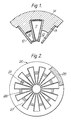
- FIG. 1 of the drawings shows two adjacent cavities of a known rising sun magnetron, cavity 10 being a short cavity and cavity 11 a long cavity.
- the cavities are defined by copper vanes 12 extending on either side of teeth-like elements 13 which are formed on a copper anode ring 14.
- the cavities act as inductive circuits.
- These notional circuits are indicated in the figure and essentially consist of an inductive element located at the base of each cavity and a capacitive element located between respective vane tips.
- One way of counteracting thermal expansion is to use a material with a very low coefficient of thermal expansion for the construction of the anode.
- One such material is molybdenum.
- molybdenum and other similar materials are very difficult to machine, and the microwave conducting surfaces must be copper-clad to maintain a high figure of merit (Q o ) to the ⁇ -mode resonance.
- the present invention thus proposes a composite anode structure which incorporates both a material like molybdenum with copper and which exploits the differing thermal coefficients of expansion of the materials employed to achieve a compensation effect by varying the inter-vane capacitance.
- a composite anode structure which incorporates both a material like molybdenum with copper and which exploits the differing thermal coefficients of expansion of the materials employed to achieve a compensation effect by varying the inter-vane capacitance.
- Figure 2 of the drawings One example of such a structure is shown in Figure 2 of the drawings.
- This figure shows an anode 20 for a rising sun magnetron.
- the anode 20 is partly of copper and partly of molybdenum.
- the areas fabricated from molybdenum are shown shaded and the remainder of the anode is of copper.
- the twenty-two equally spaced vanes 21, though shown as molybdenum, are coated with copper to maintain the required figure of merit Q o . It can thus be seen that the main body of the anode 20 contains a ring 25 of molybdenum which extends around the entire circumference of the anode.
- the anode 20 also includes eleven ring segments 26 located on the apices of teeth-like elements 27 projecting inwardly from the main anode body. As can be seen these are also of molybdenum.
- the ring elements act as fulcra about which the thermally induced stresses pivot the vanes 21.
- the tips of the vanes 21 tend to move in the opposite direction than than described in the case where the ring elements 27 were absent.
- the balance of forces can be varied by changing the lengths of the segmental ring elements 27.
- the frequency deviation which would occur due to changes in cavity lengths can be almost exactly compensated for.
- a thermal frequency coefficient of chosen value can be established.
- vanes 21, ring 25 and segmental ring elements have been described as being of molybdenum. It will be appreciated that there are alternative materials with a low thermal coefficient of expansion which can be used. Thus tungsten may replace the molybdenum. Alternatively, a matching alloy can be used. Such an alloy could be a combination selected from Copper, Tungsten and Molybdenum.
Landscapes
- Microwave Tubes (AREA)
Applications Claiming Priority (2)
| Application Number | Priority Date | Filing Date | Title |
|---|---|---|---|
| GB868613967A GB8613967D0 (en) | 1986-06-09 | 1986-06-09 | Magnetrons |
| GB8613967 | 1986-06-09 |
Publications (2)
| Publication Number | Publication Date |
|---|---|
| EP0249370A1 true EP0249370A1 (fr) | 1987-12-16 |
| EP0249370B1 EP0249370B1 (fr) | 1990-09-19 |
Family
ID=10599176
Family Applications (1)
| Application Number | Title | Priority Date | Filing Date |
|---|---|---|---|
| EP87304808A Expired EP0249370B1 (fr) | 1986-06-09 | 1987-06-01 | Magnétron |
Country Status (4)
| Country | Link |
|---|---|
| US (1) | US4774436A (fr) |
| EP (1) | EP0249370B1 (fr) |
| DE (1) | DE3765016D1 (fr) |
| GB (2) | GB8613967D0 (fr) |
Families Citing this family (1)
| Publication number | Priority date | Publication date | Assignee | Title |
|---|---|---|---|---|
| GB2357629B (en) * | 1999-12-21 | 2004-06-09 | Marconi Applied Techn Ltd | Magnetron Anodes |
Citations (8)
| Publication number | Priority date | Publication date | Assignee | Title |
|---|---|---|---|---|
| GB574934A (en) * | 1940-04-22 | 1946-01-28 | M O Valve Co Ltd | Improvements in electrical resonators |
| GB642766A (en) * | 1947-03-15 | 1950-09-13 | Philips Nv | Improvements relating to magnetron-cavity structures |
| DE905178C (de) * | 1943-06-02 | 1954-02-25 | Siemens Ag | Ultrakurzwellenroehre, insbesondere Magnetfeldroehre mit mehreren zusammenarbeitenden Hohlraumresonatoren |
| CH331670A (de) * | 1953-08-12 | 1958-07-31 | Standard Telephon & Radio Ag | Magnetron-Anodengebilde |
| US2899603A (en) * | 1955-07-06 | 1959-08-11 | Tunable magnetron | |
| US3293487A (en) * | 1961-10-04 | 1966-12-20 | English Electric Valve Co Ltd | Anode for a magnetron having deverse size cavity resonators |
| DE1904448A1 (de) * | 1968-02-02 | 1969-08-28 | English Electric Valve Co Ltd | Magnetron mit Fahnenanode |
| US3608167A (en) * | 1969-11-12 | 1971-09-28 | Varian Associates | Method for fabricating a "rising sun" magnetron anode |
Family Cites Families (4)
| Publication number | Priority date | Publication date | Assignee | Title |
|---|---|---|---|---|
| US2548808A (en) * | 1945-11-06 | 1951-04-10 | Nathan P Nichols | Continuous-strip anode for magnetrons |
| US2626372A (en) * | 1950-10-07 | 1953-01-20 | Raytheon Mfg Co | Cavity resonator structure and tube employing the same |
| US3327161A (en) * | 1963-09-28 | 1967-06-20 | Nippon Electric Co | Magnetron anode structure having cavities with rounded corners so that solder seepage cannot occur during brazing |
| US3600629A (en) * | 1969-11-12 | 1971-08-17 | Varian Associates | Tuner for providing microwave cross-field tubes with an extended temperature stabilized frequency range |
-
1986
- 1986-06-09 GB GB868613967A patent/GB8613967D0/en active Pending
-
1987
- 1987-06-01 EP EP87304808A patent/EP0249370B1/fr not_active Expired
- 1987-06-01 GB GB8712783A patent/GB2193032B/en not_active Expired - Fee Related
- 1987-06-01 DE DE8787304808T patent/DE3765016D1/de not_active Expired - Lifetime
- 1987-06-02 US US07/057,427 patent/US4774436A/en not_active Expired - Fee Related
Patent Citations (8)
| Publication number | Priority date | Publication date | Assignee | Title |
|---|---|---|---|---|
| GB574934A (en) * | 1940-04-22 | 1946-01-28 | M O Valve Co Ltd | Improvements in electrical resonators |
| DE905178C (de) * | 1943-06-02 | 1954-02-25 | Siemens Ag | Ultrakurzwellenroehre, insbesondere Magnetfeldroehre mit mehreren zusammenarbeitenden Hohlraumresonatoren |
| GB642766A (en) * | 1947-03-15 | 1950-09-13 | Philips Nv | Improvements relating to magnetron-cavity structures |
| CH331670A (de) * | 1953-08-12 | 1958-07-31 | Standard Telephon & Radio Ag | Magnetron-Anodengebilde |
| US2899603A (en) * | 1955-07-06 | 1959-08-11 | Tunable magnetron | |
| US3293487A (en) * | 1961-10-04 | 1966-12-20 | English Electric Valve Co Ltd | Anode for a magnetron having deverse size cavity resonators |
| DE1904448A1 (de) * | 1968-02-02 | 1969-08-28 | English Electric Valve Co Ltd | Magnetron mit Fahnenanode |
| US3608167A (en) * | 1969-11-12 | 1971-09-28 | Varian Associates | Method for fabricating a "rising sun" magnetron anode |
Also Published As
| Publication number | Publication date |
|---|---|
| GB2193032B (en) | 1990-01-31 |
| GB8613967D0 (en) | 1986-11-26 |
| GB8712783D0 (en) | 1987-07-08 |
| GB2193032A (en) | 1988-01-27 |
| EP0249370B1 (fr) | 1990-09-19 |
| US4774436A (en) | 1988-09-27 |
| DE3765016D1 (de) | 1990-10-25 |
Similar Documents
| Publication | Publication Date | Title |
|---|---|---|
| EP0249370B1 (fr) | Magnétron | |
| US6339294B1 (en) | Magnetron anode vanes having a face portion oriented towards the anode center | |
| US4714859A (en) | Magnetrons | |
| US4288721A (en) | Microwave magnetron-type device | |
| US4017760A (en) | Parasitic oscillation suppressor for electronic tubes | |
| GB2372147A (en) | Magnetron with radiation absorbing dielectric resonator | |
| US3163835A (en) | Voltage-tuneable microwave reactive element utilizing semiconductor material | |
| EP0316092A1 (fr) | Anodes de magnétrons | |
| US3389283A (en) | Electrode structure cyclotron having grounded coupling plates between the dee-rings | |
| JP3397826B2 (ja) | マグネトロン陽極体 | |
| KR100323704B1 (ko) | 마그네트론 | |
| US6831416B1 (en) | Inductive compensator for magnetron | |
| US5483123A (en) | High impedance anode structure for injection locked magnetron | |
| US6078141A (en) | Magnetron with improved vanes | |
| JP4326920B2 (ja) | マグネトロン | |
| US2668929A (en) | Magnetron | |
| EP1139485B1 (fr) | Compensation thermique d'un dispositif pour filtre micro-ondes | |
| JP4401854B2 (ja) | マグネトロン | |
| KR100218438B1 (ko) | 마그네트론의 양극구조 | |
| KR200321345Y1 (ko) | 마그네트론양극부의열적안정화구조 | |
| JPH065211A (ja) | マグネトロン | |
| Fowkes et al. | Design considerations for very high power RF windows at X-band | |
| JPH0652805A (ja) | マグネトロン | |
| GB2331180A (en) | Magnetrons | |
| EP0209219A1 (fr) | Magnétrons coaxiaux |
Legal Events
| Date | Code | Title | Description |
|---|---|---|---|
| PUAI | Public reference made under article 153(3) epc to a published international application that has entered the european phase |
Free format text: ORIGINAL CODE: 0009012 |
|
| AK | Designated contracting states |
Kind code of ref document: A1 Designated state(s): DE FR IT SE |
|
| 17P | Request for examination filed |
Effective date: 19880614 |
|
| 17Q | First examination report despatched |
Effective date: 19890714 |
|
| GRAA | (expected) grant |
Free format text: ORIGINAL CODE: 0009210 |
|
| RAP1 | Party data changed (applicant data changed or rights of an application transferred) |
Owner name: E.E.V. LIMITED |
|
| AK | Designated contracting states |
Kind code of ref document: B1 Designated state(s): DE FR IT SE |
|
| ITF | It: translation for a ep patent filed | ||
| ET | Fr: translation filed | ||
| REF | Corresponds to: |
Ref document number: 3765016 Country of ref document: DE Date of ref document: 19901025 |
|
| PG25 | Lapsed in a contracting state [announced via postgrant information from national office to epo] |
Ref country code: SE Effective date: 19910602 |
|
| PLBE | No opposition filed within time limit |
Free format text: ORIGINAL CODE: 0009261 |
|
| STAA | Information on the status of an ep patent application or granted ep patent |
Free format text: STATUS: NO OPPOSITION FILED WITHIN TIME LIMIT |
|
| 26N | No opposition filed | ||
| PG25 | Lapsed in a contracting state [announced via postgrant information from national office to epo] |
Ref country code: FR Effective date: 19920228 |
|
| PG25 | Lapsed in a contracting state [announced via postgrant information from national office to epo] |
Ref country code: DE Effective date: 19920401 |
|
| REG | Reference to a national code |
Ref country code: FR Ref legal event code: ST |
|
| EUG | Se: european patent has lapsed |
Ref document number: 87304808.6 Effective date: 19920109 |
|
| PG25 | Lapsed in a contracting state [announced via postgrant information from national office to epo] |
Ref country code: IT Free format text: LAPSE BECAUSE OF NON-PAYMENT OF DUE FEES;WARNING: LAPSES OF ITALIAN PATENTS WITH EFFECTIVE DATE BEFORE 2007 MAY HAVE OCCURRED AT ANY TIME BEFORE 2007. THE CORRECT EFFECTIVE DATE MAY BE DIFFERENT FROM THE ONE RECORDED. Effective date: 20050601 |