EP0249414A2 - Berührungslose Bahntrageführung - Google Patents
Berührungslose Bahntrageführung Download PDFInfo
- Publication number
- EP0249414A2 EP0249414A2 EP87304998A EP87304998A EP0249414A2 EP 0249414 A2 EP0249414 A2 EP 0249414A2 EP 87304998 A EP87304998 A EP 87304998A EP 87304998 A EP87304998 A EP 87304998A EP 0249414 A2 EP0249414 A2 EP 0249414A2
- Authority
- EP
- European Patent Office
- Prior art keywords
- web
- support
- support face
- pockets
- air
- Prior art date
- Legal status (The legal status is an assumption and is not a legal conclusion. Google has not performed a legal analysis and makes no representation as to the accuracy of the status listed.)
- Withdrawn
Links
- 238000000034 method Methods 0.000 claims description 6
- 230000001419 dependent effect Effects 0.000 description 4
- 230000008901 benefit Effects 0.000 description 2
- 238000001035 drying Methods 0.000 description 2
- 238000012423 maintenance Methods 0.000 description 2
- 230000004048 modification Effects 0.000 description 2
- 238000012986 modification Methods 0.000 description 2
- 230000009172 bursting Effects 0.000 description 1
- 230000008859 change Effects 0.000 description 1
- 230000000694 effects Effects 0.000 description 1
- 230000006872 improvement Effects 0.000 description 1
- 230000008569 process Effects 0.000 description 1
- 230000009467 reduction Effects 0.000 description 1
- 230000003068 static effect Effects 0.000 description 1
Images


Classifications
-
- B—PERFORMING OPERATIONS; TRANSPORTING
- B65—CONVEYING; PACKING; STORING; HANDLING THIN OR FILAMENTARY MATERIAL
- B65H—HANDLING THIN OR FILAMENTARY MATERIAL, e.g. SHEETS, WEBS, CABLES
- B65H23/00—Registering, tensioning, smoothing or guiding webs
- B65H23/04—Registering, tensioning, smoothing or guiding webs longitudinally
- B65H23/24—Registering, tensioning, smoothing or guiding webs longitudinally by fluid action, e.g. to retard the running web
-
- B—PERFORMING OPERATIONS; TRANSPORTING
- B65—CONVEYING; PACKING; STORING; HANDLING THIN OR FILAMENTARY MATERIAL
- B65H—HANDLING THIN OR FILAMENTARY MATERIAL, e.g. SHEETS, WEBS, CABLES
- B65H2406/00—Means using fluid
- B65H2406/10—Means using fluid made only for exhausting gaseous medium
- B65H2406/11—Means using fluid made only for exhausting gaseous medium producing fluidised bed
- B65H2406/111—Means using fluid made only for exhausting gaseous medium producing fluidised bed for handling material along a curved path, e.g. fluidised turning bar
Definitions
- This invention relates to a contactless support guide for a web of material.
- Contactless web support guides are incorporated in printing machines, usually when it is required to print both sides of a web of material without intermediate drying between the two printing processes. In effect, they are air bearing devices which replace specific rollers of the printing machine, thereby preventing smudging.
- Such support guides are used to change the direction of motion of a web (usually through 90°), in which case they are referred to as "air turns”. Air turns are usually used in pairs to reverse the direction of motion of a web. Similar support guides (known as “air bars”) are used to support and guide webs without changing their direction of motion.
- the aim of the invention is to provide a contactless support guide which maintains the stability of the web at high speeds, and is quieter than known devices.
- the present invention provides a contactless support guide for a web of material, the guide comprising a web support face, and a pressurised air supply manifold, wherein the support face is provided with a plurality of pockets, wherein means are provided for directing pressurised air into the pockets whereby the web can be supported in spaced relationship to the support face by an air cushion, and wherein means are provided for increasing the air pressure at the web entry and exit regions of the support face.
- a plenum chamber is positioned between the manifold and the support face.
- each pocket may be provided with an air inlet aperture leading to the plenum chamber, the inlet apertures constituting the means for directing pressurised air into the pockets.
- the inlet apertures of the pockets in the region of the support face which is central with respect to the direction of movement of a web over the support face are smaller than the inlet apertures of the pockets at the web entry and exit regions of the support face.
- the inlet apertures of the pockets in said central region have a diameter of 1/16th inch
- the inlet apertures of the pockets in said entry and exit regions have a diameter of 1/4 inch, the diameters of the inlet apertures being graded from said central region to the entry and exit regions.
- the pockets are arranged in rows which extend at right-angles to the direction of movement of a web over the support face.
- the guide may further comprise slats positioned at the web entry and exit regions, each slat partially overlying, or projecting into, the pockets of the adjacent row, the slats constituting the means for increasing the air pressure at the web entry and exit regions.
- each of the slats is adjustably mounted on the support face, and the leading edge of each slat is inclined.
- the guide further comprises an elongate pocket extending along each of the longitudinal edges of the support face at the web entry and exit regions, each elongate pocket being provided with a plurality of inlet apertures leading to the plenum chamber, the elongate pockets and their inlet apertures being angled towards the centre of the support face, the elongate pockets and their inlet apertures constituting the means for increasing the air pressure at the web entry and exit regions.
- each of the elongate pockets has a width of 3/8 inch and a maximum depth of 3/8 inch, and the inlet apertures each have a diameter of 3/16 inch and are spaced apart by 1/4 inch.
- each of the pockets is circular, having a diameter of 1 inch and a depth of 3/8 inch.
- the guide further comprises an air distribution baffle positioned in the plenum chamber in the air flow path from the manifold to the support face.
- the baffle is formed with a plurality of apertures.
- the manifold is constituted by a pair of tubes positioned at the longitudinal edges of the support face, each of the tubes being provided with a plurality of holes through which pressurised air can be directed towards the adjacent longitudinal edge of the support face, said holes constituting the means for directing pressurised air into the pockets and the means for increasing the air pressure at the web entry and exit regions of the support face.
- the support face is arcuate and of such dimensions as to support the guide a web for movement through an angle of substantially 90°.
- the support face is gently curved so as to support and guide a web moving generally rectalinearly.
- the invention also provides a method of maintaining the lateral stability of a web of material passing over a contactless support guide comprising a web support face and a pressurised air supply manifold, the method comprising the step of applying pressurised air to the web entry and exit regions of the support face in such a manner as to cause ridging of the web in the direction of movement of the web over the support face.
- pressurised air is applied to said web entry and exit regions via respective elongate pockets provided at the longitudinal edges of the support face, each of said elongate pockets being supplied with pressurised air via a plurality of inlet apertures extending along that aperture.
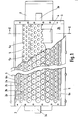
- Figs. 1 and 2 show a contactless web support guide known as an air turn.
- the air turn has a tubular air supply manifold 1, and an arcuate support face 2 supported on the manifold by a body 3.
- the air turn is supported by a pair of handles 3a provided at the ends of the body 3.
- a cut-out 4 formed in the manifold 1 permits air to pass from the manifold to the support face 2.
- the body 3 defines a plenum chamber 3b between the manifold 1 and the support face 2.
- the plenum chamber 3b helps to equalise air pressure along the length of the support guide.
- the support face 2 has a length of about 3 feet and a radius of about 6 inches.
- the arcuate support face 2 extends over an arc which is sufficiently long to guide a web passing thereover through a substantially 90° turn.
- An air spreader baffle 5 is fixed to the body 3 within the plenum chamber 3b in the air flow path from the cut-out 4 to the support face 2. The baffle 5 helps to even out the air pressure along the air turn device, having a large number of circular apertures 5a of 1/2 inch diameter.
- the support face 2 is provided with rows of circular pockets 2a, each having a diameter of 1 inch and a depth of 3/8 inch.
- the pockets are supplied with air via inlet holes 2b.
- the inlet holes 2b adjacent to the longitudinal edges of the support face 2 have a diameter of 1/4 inch, the inlet holes at the centre have a diameter meter of 1/16 inch, and the remaining inlet holes have diameters graded from 1/16 inch at the centre to 1/4 inch at the edges of the support face.
- An adjustable slat 6 is provided at each of the longitudinal edges of the support face 2. Each slat 6 overlies the pockets 2a of the row of pockets adjacent to that edge. Each slat 6 has a sloping leading edge 6a.
- pressurised air is supplied to the manifold 1.
- This air passes through the apertures 5a in the baffle 5, and out over the support face 2 via the holes 2b and the pockets 2a.
- the air emerging from the pockets 2a forms a pressurised cushion between the support face 2 and a web of material (not shown) which is supported and guided by the air turn.
- the pressurised air is supplied to the manifold 1 by an impeller (not shown) which is controlled by an orthodox controllor (not shown) whose output is dependent upon the web tension.
- an impeller not shown
- an orthodox controllor not shown
- the provision of the slats 6 also helps to ensure the maintenance of air pressure at these entry and exit regions, the slats creating a local increase in pressure (see Fig. 3 which shows the exit region of the air turn, and how the pressure build-up - indicated by the small arrows - pushes the web W away from the support face 2).
- the adjustability of the slats 6 permits adjustment of the pressure of the air cushion at the longitudinal edges of the support face 2.
- the sloping edges 6a of the slats 6 divert the air flow obliquely away from the support face 2, thereby pushing the web away from the support face at the entry and exit regions.
- this air turn also has the advantage of being relatively silent when compared with known air turn devices which rely on jets of air at the entry and exit regions.
- Fig. 4 shows a modified arrangement which results in an increase in the air pressure at the two longitudinal edges of the support face 2. This improvement is achieved by positioning the slats 6 so as to project into the adjacent pockets 2a (rather than overlying them as in the case with the embodiment shown in Figs. 1 to 3), and by providing each of these pockets with two or more holes 2b. This results in an increase in the air pressure in the pockets 2a adjacent to the longitudinal edges of the support face 2.
- Fig. 5 shows a second form of contactless web support guide.
- This support guide (air bar) is intended to support and guide a web travelling generally in a rectalinear manner.
- this support guide has an arcuate support face 12 which is curved only slightly.
- this support guide is similar to the air turn shown in Figs. 1 and 2, in that it has a supply manifold 11, a body 13 having a pair of handles 13a, a plenum chamber 13b, cut-out 14, an air spreader baffle 15 having apertures 15a and holes 15b, and a pair of adjustable slats 16 having inclined leading edges 16a.
- the pockets 12a are arranged in rows (in this case three rows), the holes 12b in the centre having a diameter of 1/16 inch and the holes 12b in the two outer rows having a diameter of 1/4 inch.
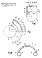
- Figs. 6 and 7 shows a third form of contactless web support guide which is a modification of that shown in Figs. 1 to 3.
- the air turn has a tubular air supply manifold 21, and an arcuate support face 22 supported on the manifold by a body 23.
- the air turn is supported by a pair of handles 23a provided at the ends of the body 23.
- a cut-out 24 formed in the manifold 21 permits air to pass from the manifold to the support face 22.
- the body 23 defines a plenum chamber 23b between the manifold 21 and the support face 22.
- the support face 22 has a length of about 3 feet and a radius of about 6 inches.
- the arcuate support face 22 extends over an arc which is sufficiently long to guide a web passing thereover through a substantially 90° turn.
- An air spreader baffle 25 is fixed to the body 23 in the air flow path from the cut-out 24 to the support face 22. The baffle 25 helps to even out the air pressure along the air turn device, having a large number of circular apertures 25a of 1/2 inch diameter.
- the support face 22 is provided with rows of circular pockets 22a, each having a diameter of 1 inch and a depth of 3/8 inch.
- the pockets 22a are supplied with air via inlet holes 22b.
- the inlet holes 22b have a diameter of 1/8 inch.
- Adjacent to each longitudinal edge, the support face 22 is provided with an elongate pocket 22 ⁇ a, each of which has a width of 3/8 inch and a maximum depth of 3/8 inch.
- the pockets 22 ⁇ a are supplied with pressurised air via inlet holes 22 ⁇ b which have a diameter of 3/16 inch and which are spaced apart by 1/4 inch.
- the pockets 22 ⁇ a and the inlet holes 22 ⁇ b adjacent to the longitudinal edges of the support faces 22 of this air turn are angled towards the centre of the support face.
- pressurised air is supplied to the manifold 21.
- This air passes through the apertures 25a in the baffle 25, and out over the support face 22 via the holes 22b, 22 ⁇ b and the pockets 22a, 22 ⁇ a.
- the air emerging from the pockets 22a, 22 ⁇ a forms a pressurised cushion between the support faces 22 and a web of material (not shown) which is supported and guided by the air turn.
- the pressurised air is supplied to the manifold 21 by an impeller (not shown) which is controlled by an orthodox controller (not shown) whose output is dependent upon the web tension.
- the pressure of air cushion at the support face 22 is dependent upon the web tension.
- the provision of the angled pockets 22 ⁇ a and inlet holes 22 ⁇ b at the longitudinal edges of the support face 22 also helps to ensure the maintenance of air pressure at these entry and exit regions, and also diverts the air flow obliquely away from the support face 22, thereby pushing the web away from the support face at the entry and exit regions.
- this air turn also has the advantage of being relatively silent when compared with known air turn devices which rely on jets of air at the entry and exit regions.
- Figs. 6 and 7 can work with much higher web tensions that those of Figs. 1 to 4, and so is the preferred embodiment of the invention.
- the pockets 22a are supplied with pressurised air indirectly - via the pockets 22 ⁇ a and the web of material.
- Fig. 8 shows a further form of contactless web support guide whose circular apertures are not directly supplied with pressurised air.
- Fig. 8 shows an air turn having a pair of tubular air supply tubes 31, and an arcuate support face 32 whose longitudinal edges are fixed to the air supply tubes.
- Each of the tubes 31 has an external diameter of 3 inches, an internal diameter of 2 1/2 inches, and is provided with a plurality of holes 36 extending along that tube in line with the adjacent longitudinal edge of the support face 32.
- the holes have a diameter of 3/16 inch, a spacing of 1/4 inch, and are positioned to direct air flow from the tube interior to towards the adjacent longitudinal edge of the support face 32.
- the support face 32 has a length of about 3 feet and a radius of about 6 inches.
- the support face 32 is provided with rows of circular pockets 32a, each having a diameter of 1 inch and a depth of 3/8 inch.
- the pockets 32a are distributed in a similar manner to the pockets 2a of the embodiment of Fig. 1.
- pressurised air is supplied to the tubes 31 via inlets (not shown) formed in their central regions.
- This pressurised air emerges from the holes 36 and forms a pressurised air cushion behind a web (not shown) of material passing over the support face 32.
- the web itself is instrumental in directing the air flow over the support face 32 and into the pockets 32a.
Landscapes
- Advancing Webs (AREA)
- Treatment Of Fiber Materials (AREA)
- Registering, Tensioning, Guiding Webs, And Rollers Therefor (AREA)
Applications Claiming Priority (4)
| Application Number | Priority Date | Filing Date | Title |
|---|---|---|---|
| GB8613764 | 1986-06-06 | ||
| GB868613764A GB8613764D0 (en) | 1986-06-06 | 1986-06-06 | Contactless web support guide |
| GB8710433 | 1987-05-01 | ||
| GB878710433A GB8710433D0 (en) | 1987-05-01 | 1987-05-01 | Contactless web support guide |
Publications (2)
| Publication Number | Publication Date |
|---|---|
| EP0249414A2 true EP0249414A2 (de) | 1987-12-16 |
| EP0249414A3 EP0249414A3 (de) | 1989-11-15 |
Family
ID=26290872
Family Applications (1)
| Application Number | Title | Priority Date | Filing Date |
|---|---|---|---|
| EP87304998A Withdrawn EP0249414A3 (de) | 1986-06-06 | 1987-06-05 | Berührungslose Bahntrageführung |
Country Status (3)
| Country | Link |
|---|---|
| US (1) | US4824002A (de) |
| EP (1) | EP0249414A3 (de) |
| GB (1) | GB2194918B (de) |
Cited By (6)
| Publication number | Priority date | Publication date | Assignee | Title |
|---|---|---|---|---|
| DE3936846C1 (de) * | 1989-11-06 | 1991-04-18 | Hilmar 5653 Leichlingen De Vits | |
| US5437521A (en) * | 1993-05-13 | 1995-08-01 | Ouellette Machinery Systems, Inc. | Air conveyor for bottles |
| EP2053663A1 (de) * | 2007-10-25 | 2009-04-29 | Applied Materials, Inc. | Luftkissentransport für Bahnen bei einem Bahnbeschichtungsverfahren |
| EP2216831A1 (de) * | 2009-02-05 | 2010-08-11 | Applied Materials, Inc. | Modulares PVD-System für Flex PV |
| EP2278047A1 (de) * | 2005-08-31 | 2011-01-26 | Konica Minolta Holdings, Inc. | Plasmaentladungsbehandlungsvorrichtung und Verfahren zur Herstellung einer Gassperrfolie |
| DE102014113047A1 (de) * | 2013-09-19 | 2015-03-19 | Von Ardenne Gmbh | Vakuumbeschichtungsanlage und Verfahren zur Beschichtung bandförmiger Substrate |
Families Citing this family (11)
| Publication number | Priority date | Publication date | Assignee | Title |
|---|---|---|---|---|
| DE3827071A1 (de) * | 1988-08-10 | 1990-02-15 | Roland Man Druckmasch | Luftkissentrommel fuer bogendruckmaschinen |
| US4925080A (en) * | 1988-10-13 | 1990-05-15 | Beloit Corporation | Spreader bar apparatus |
| DE3914310A1 (de) * | 1989-04-29 | 1990-10-31 | Eltex Elektrostatik Gmbh | Vorrichtung zum abfuehren des staubes in falzapparaten fuer druckmaschinen |
| EP0563290A1 (de) * | 1990-12-19 | 1993-10-06 | Eastman Kodak Company | Berührungslose bahnwendestangen und bahnumkehrvorrichtungen mit schräg angeordneten löchern |
| DE4311438C2 (de) * | 1993-04-07 | 1997-06-19 | Koenig & Bauer Albert Ag | Wendestange für eine Materialbahn |
| US5590480A (en) * | 1994-12-06 | 1997-01-07 | W. R. Grace & Co.-Conn. | combination air bar and hole bar flotation dryer |
| DE29508421U1 (de) * | 1995-05-20 | 1995-09-14 | Voith Sulzer Papiermaschinen GmbH, 89522 Heidenheim | Stationäre Gleitleiste |
| CH693304A5 (de) * | 1997-08-01 | 2003-05-30 | Roland Man Druckmasch | Wendestange und Wendestangenanordnung für eine Rollenrotationsdruckmaschine. |
| US6364247B1 (en) | 2000-01-31 | 2002-04-02 | David T. Polkinghorne | Pneumatic flotation device for continuous web processing and method of making the pneumatic flotation device |
| JP4143520B2 (ja) * | 2003-11-11 | 2008-09-03 | 富士フイルム株式会社 | 無接触搬送装置 |
| KR101021764B1 (ko) | 2008-10-07 | 2011-03-17 | 성안기계 (주) | 에어 턴 어셈블리 및 그를 구비한 원단 지지장치 |
Family Cites Families (10)
| Publication number | Priority date | Publication date | Assignee | Title |
|---|---|---|---|---|
| GB477042A (en) * | 1935-06-20 | 1937-12-20 | Vomag Betr Ag | Guiding device for webs of materials such as printed webs in rotary printing machines |
| ES274570A1 (es) * | 1961-02-18 | 1962-10-16 | Svenska Flaektfabriken Ab | Dispositivo de giro para un material en forma de lamina para el secado y otros tratamientos del papel, celulosa y materiales analogos |
| US3313462A (en) * | 1966-06-02 | 1967-04-11 | Hupp Corp | Air flotation direction changing roll |
| GB1307695A (en) * | 1970-08-19 | 1973-02-21 | Ilford Ltd | Air flotation turner bars |
| BE795259A (fr) * | 1972-02-10 | 1973-08-09 | Saint Gobain | Dispositif generateur de coussins gazeux pour le support de feuilles du rubans |
| US3984039A (en) * | 1974-12-16 | 1976-10-05 | International Business Machines Corporation | Precision-surface with dynamically-stiff air film provided by deep pools |
| US4182472A (en) * | 1978-07-13 | 1980-01-08 | W. R. Grace & Co. | Contactless turning guide for running webs |
| US4197972A (en) * | 1978-08-28 | 1980-04-15 | W. R. Grace & Co. | Contactless turning guide having air slots longitudinally along running web edges |
| US4288015A (en) * | 1980-02-11 | 1981-09-08 | W. R. Grace & Co. | Contactless web turning guide |
| US4282998A (en) * | 1980-05-09 | 1981-08-11 | W. R. Grace & Co. | Maintenance of constant web clearance at contactless turning guide |
-
1987
- 1987-06-04 US US07/058,279 patent/US4824002A/en not_active Expired - Fee Related
- 1987-06-05 GB GB8713165A patent/GB2194918B/en not_active Expired - Lifetime
- 1987-06-05 EP EP87304998A patent/EP0249414A3/de not_active Withdrawn
Cited By (9)
| Publication number | Priority date | Publication date | Assignee | Title |
|---|---|---|---|---|
| DE3936846C1 (de) * | 1989-11-06 | 1991-04-18 | Hilmar 5653 Leichlingen De Vits | |
| EP0427015A3 (en) * | 1989-11-06 | 1991-08-21 | Hilmar Vits | Device for suspended transport web or sheet materials |
| US5102118A (en) * | 1989-11-06 | 1992-04-07 | Hilmar Vits | Device for floatably guiding webs or sheets of material to be conveyed |
| US5437521A (en) * | 1993-05-13 | 1995-08-01 | Ouellette Machinery Systems, Inc. | Air conveyor for bottles |
| EP2278047A1 (de) * | 2005-08-31 | 2011-01-26 | Konica Minolta Holdings, Inc. | Plasmaentladungsbehandlungsvorrichtung und Verfahren zur Herstellung einer Gassperrfolie |
| EP2053663A1 (de) * | 2007-10-25 | 2009-04-29 | Applied Materials, Inc. | Luftkissentransport für Bahnen bei einem Bahnbeschichtungsverfahren |
| WO2009053289A1 (en) * | 2007-10-25 | 2009-04-30 | Applied Materials, Inc. | Hover cushion transport for webs in a web coating process |
| EP2216831A1 (de) * | 2009-02-05 | 2010-08-11 | Applied Materials, Inc. | Modulares PVD-System für Flex PV |
| DE102014113047A1 (de) * | 2013-09-19 | 2015-03-19 | Von Ardenne Gmbh | Vakuumbeschichtungsanlage und Verfahren zur Beschichtung bandförmiger Substrate |
Also Published As
| Publication number | Publication date |
|---|---|
| EP0249414A3 (de) | 1989-11-15 |
| GB8713165D0 (en) | 1987-07-08 |
| GB2194918A (en) | 1988-03-23 |
| GB2194918B (en) | 1990-10-17 |
| US4824002A (en) | 1989-04-25 |
Similar Documents
| Publication | Publication Date | Title |
|---|---|---|
| EP0249414A2 (de) | Berührungslose Bahntrageführung | |
| US4197972A (en) | Contactless turning guide having air slots longitudinally along running web edges | |
| US6443389B1 (en) | Self threading air bar | |
| US4919319A (en) | Contactless web support guide | |
| US3231165A (en) | Method and apparatus for stabilizing an air-borne web | |
| US4182472A (en) | Contactless turning guide for running webs | |
| US6004432A (en) | Sheet turn with vectored air supply | |
| US3485429A (en) | Device for heating and drying a material web by suspension in a tunnel | |
| US6505792B1 (en) | Non-contact floating device for turning a floating web | |
| JPH0268480A (ja) | ウエブを浮動状態で支持案内するドライヤー | |
| GB2068876A (en) | Contactless web turning guide | |
| US3800438A (en) | Apparatus for treatment of materials, particularly the heat treatment of webs | |
| US3498515A (en) | Fluid cushion turning rolls for supporting and guiding strip material | |
| WO1992011194A1 (en) | Non-contact web turnbars and reversers with angled holes | |
| US6302353B1 (en) | Turning bar apparatus | |
| US5172844A (en) | Method and apparatus for reducing a transporting strain on elongated material passing through a treatment chamber | |
| US5354007A (en) | Web leader guiding device utilizing turbulence-generating nozzles | |
| JP4954439B2 (ja) | 空気圧式の枚葉紙案内装置を備える枚葉紙処理機械 | |
| KR100549479B1 (ko) | 테이블 요소, 테이블 요소를 포함하는 웨브 이송 시스템, 및 테이블 요소를 이용하여 웨브를 이송시키는 방법 | |
| GB2384295A (en) | A fabric dryer | |
| EP0675064B1 (de) | Luftleitflügel für eine pneumatische Wendestange | |
| FI115233B (fi) | Laitteisto päänvientinauhan kuljettamiseksi paperikoneessa | |
| GB1584770A (en) | Guide device for flexible webs | |
| FI116229B (fi) | Sivuohjauksella varustettu alipainehihnakuljetin rainanmuodostuskonetta varten | |
| US3232507A (en) | Arrangement in devices for supporting and conveying airborne materials |
Legal Events
| Date | Code | Title | Description |
|---|---|---|---|
| PUAI | Public reference made under article 153(3) epc to a published international application that has entered the european phase |
Free format text: ORIGINAL CODE: 0009012 |
|
| AK | Designated contracting states |
Kind code of ref document: A2 Designated state(s): AT BE CH DE ES FR GB GR IT LI NL SE |
|
| PUAL | Search report despatched |
Free format text: ORIGINAL CODE: 0009013 |
|
| AK | Designated contracting states |
Kind code of ref document: A3 Designated state(s): AT BE CH DE ES FR GB GR IT LI NL SE |
|
| 17P | Request for examination filed |
Effective date: 19891028 |
|
| 17Q | First examination report despatched |
Effective date: 19910308 |
|
| STAA | Information on the status of an ep patent application or granted ep patent |
Free format text: STATUS: THE APPLICATION IS DEEMED TO BE WITHDRAWN |
|
| 18D | Application deemed to be withdrawn |
Effective date: 19921201 |