EP0249459B1 - Dispositif de serrage - Google Patents
Dispositif de serrage Download PDFInfo
- Publication number
- EP0249459B1 EP0249459B1 EP87305136A EP87305136A EP0249459B1 EP 0249459 B1 EP0249459 B1 EP 0249459B1 EP 87305136 A EP87305136 A EP 87305136A EP 87305136 A EP87305136 A EP 87305136A EP 0249459 B1 EP0249459 B1 EP 0249459B1
- Authority
- EP
- European Patent Office
- Prior art keywords
- wedge
- elongate member
- collar
- elongate
- recess
- Prior art date
- Legal status (The legal status is an assumption and is not a legal conclusion. Google has not performed a legal analysis and makes no representation as to the accuracy of the status listed.)
- Expired - Lifetime
Links
- 238000000034 method Methods 0.000 claims description 8
- 239000000463 material Substances 0.000 claims description 6
- 239000004033 plastic Substances 0.000 claims description 3
- 229920003023 plastic Polymers 0.000 claims description 3
- 230000006835 compression Effects 0.000 claims description 2
- 238000007906 compression Methods 0.000 claims description 2
- 239000012858 resilient material Substances 0.000 claims description 2
- 229920002430 Fibre-reinforced plastic Polymers 0.000 claims 1
- 239000003365 glass fiber Substances 0.000 claims 1
- 230000000063 preceeding effect Effects 0.000 claims 1
- 238000011068 loading method Methods 0.000 description 6
- 238000013459 approach Methods 0.000 description 2
- 230000007423 decrease Effects 0.000 description 2
- 239000011152 fibreglass Substances 0.000 description 2
- 238000003825 pressing Methods 0.000 description 2
- 208000034564 Coronary ostial stenosis or atresia Diseases 0.000 description 1
- 241001442234 Cosa Species 0.000 description 1
- 244000089409 Erythrina poeppigiana Species 0.000 description 1
- 235000009776 Rathbunia alamosensis Nutrition 0.000 description 1
- 229910000831 Steel Inorganic materials 0.000 description 1
- 238000004458 analytical method Methods 0.000 description 1
- 238000011109 contamination Methods 0.000 description 1
- 230000007812 deficiency Effects 0.000 description 1
- 230000000694 effects Effects 0.000 description 1
- 239000000314 lubricant Substances 0.000 description 1
- 238000004519 manufacturing process Methods 0.000 description 1
- 230000013011 mating Effects 0.000 description 1
- 230000002035 prolonged effect Effects 0.000 description 1
- 230000000717 retained effect Effects 0.000 description 1
- 239000010959 steel Substances 0.000 description 1
Images


Classifications
-
- F—MECHANICAL ENGINEERING; LIGHTING; HEATING; WEAPONS; BLASTING
- F16—ENGINEERING ELEMENTS AND UNITS; GENERAL MEASURES FOR PRODUCING AND MAINTAINING EFFECTIVE FUNCTIONING OF MACHINES OR INSTALLATIONS; THERMAL INSULATION IN GENERAL
- F16B—DEVICES FOR FASTENING OR SECURING CONSTRUCTIONAL ELEMENTS OR MACHINE PARTS TOGETHER, e.g. NAILS, BOLTS, CIRCLIPS, CLAMPS, CLIPS OR WEDGES; JOINTS OR JOINTING
- F16B2/00—Friction-grip releasable fastenings
- F16B2/02—Clamps, i.e. with gripping action effected by positive means other than the inherent resistance to deformation of the material of the fastening
- F16B2/14—Clamps, i.e. with gripping action effected by positive means other than the inherent resistance to deformation of the material of the fastening using wedges
-
- Y—GENERAL TAGGING OF NEW TECHNOLOGICAL DEVELOPMENTS; GENERAL TAGGING OF CROSS-SECTIONAL TECHNOLOGIES SPANNING OVER SEVERAL SECTIONS OF THE IPC; TECHNICAL SUBJECTS COVERED BY FORMER USPC CROSS-REFERENCE ART COLLECTIONS [XRACs] AND DIGESTS
- Y10—TECHNICAL SUBJECTS COVERED BY FORMER USPC
- Y10T—TECHNICAL SUBJECTS COVERED BY FORMER US CLASSIFICATION
- Y10T403/00—Joints and connections
- Y10T403/70—Interfitted members
- Y10T403/7062—Clamped members
- Y10T403/7064—Clamped members by wedge or cam
- Y10T403/7066—Clamped members by wedge or cam having actuator
-
- Y—GENERAL TAGGING OF NEW TECHNOLOGICAL DEVELOPMENTS; GENERAL TAGGING OF CROSS-SECTIONAL TECHNOLOGIES SPANNING OVER SEVERAL SECTIONS OF THE IPC; TECHNICAL SUBJECTS COVERED BY FORMER USPC CROSS-REFERENCE ART COLLECTIONS [XRACs] AND DIGESTS
- Y10—TECHNICAL SUBJECTS COVERED BY FORMER USPC
- Y10T—TECHNICAL SUBJECTS COVERED BY FORMER US CLASSIFICATION
- Y10T403/00—Joints and connections
- Y10T403/76—Joints and connections having a cam, wedge, or tapered portion
Definitions
- This invention relates to a clamp member and to a method of releasably clamping the clamp member on an elongate member so that the clamp member can be constrained from longitudinal movement along the elongate member in one or both directions.
- the invention more particularly concerns an improved method of clamping fittings onto smooth shafts such as rounded steel or fibreglass fence posts, and provides various forms of clamp member which are able to perform the method of the invention.
- a wide variety of apparatus adapted to lock clamp members or collar members onto smooth shafts have been known in the art, including (but not limited to) radially disposed "grub screws"; locking rings which pivot in a manner such that attempted movement along the shaft results in the locking ring/s being forced into tighter contact with the shaft through a cantilever action; interlocking cones which can be wedged either actively or passively, into frictional engagement with the shaft and one another; bands which can be constricted around the shaft by means of threads or cam-lever systems.
- This invention relates to the kind of clamp member which includes a collar member having an internal bore for receiving a substantially circular, in cross-section, elongate member, there being at least one recess opening into the bore, said recess including an outer surface which is tapered with respect to the longitudinal axis of the internal bore; and at least one wedge member adapted, in use, to be positioned in the recess of the collar member between said tapered outer surface thereof and the surface of the elongate member.
- the wedge member has the same curvature as the elongate member and fits around the elongate member with continuous surface to surface contact.
- the invention accordingly provides a clamp member of the kind described, characterised in that the inner surface of said wedge member is shaped to provide at least two spaced apart areas of contact which, in normal use of the clamp member, engage the elongate member in such a way that, the planes which extend tangentially to the surface of the elongate member at the points of contact thereof with the respective contact areas of the wedge are at an oblique angle with respect to one another, the arrangement being such that, in use, the inner surface of the wedge member is engaged with the surface of the elongate member by movement of the collar member in one direction, whereupon the two spaced apart contact areas on the inner surface of the wedge member become frictionally engaged with the elongate member and the said tapered outer surface of the recess is moved into frictional engagement with the outer surface of the wedge member to frictionally engage the clamp member on the elongate member, the clamp member being disengageable from the elongate member by moving the collar member in the opposite direction.
- a clamp member as described in the preceding paragraphs wherein the recess is tapered outwardly from one or both ends of the collar member and wherein the wedge member has an inner surface engageable with the elongate member and an outer surface which is tapered from both ends substantially to correspond with the taper of the inner surface of the collar member.
- the longitudinal recess in the clamp member is tapered from one or both ends of the collar member and wherein the inner surface of the wedge member is, in cross section, of a lesser radius than the radius of the substantially circular (in cross section) elongate member to be inserted therein, the wedge member thus being adapted to contact the surface of the elongate member at the two areas of contact, the tangents of which are disposed at an oblique angle one to the other, the outer surface of the wedge member being tapered from both ends substantially to correspond with the taper of the inner surface of the collar member.
- the wedge member is constructed from an at least partially resilient material, in order that the spaced apart areas of contact are adapted, in use, to be wedged at least partially apart, the wedge member thus being adapted to be held in constant compression within the recess in the collar member, in order to accommodate variations in the diameter of the elongate member or surface irregularities of the elongate member located within said bore.
- a further possible embodiment of the clamp member includes an upstanding ridge or a recess on the inner surface of the wedge member, the ridge or the recess being positioned substantially between the two spaced apart areas of contact of the wedge member, the ridge or recess portion being adapted to engage a corresponding recess or ridge provided on the surface of the elongate member, the arrangement being such that the inner surface of the wedge member is engageable with the elongate member, while at the same time the collar member is movable relative to the outer surface of the wedge member.
- the clamp member is adapted to engage an elongate member in the form of a substantially circular (in cross section) fibreglass fencepost, wherein the collar member is provided with appropriate means to locate a fence wire, and wherein the collar member and wedge member are formed of an at least partially resilient plastic material which enables the clamp member to accommodate variations in the outer circumference of the substantially circular fence post.
- a method of clamping a clamp member as described above to a rounded (in cross section) elongate member comprising the steps of: positioning at least one wedge member in the recess of the internal bore; aligning the inner surface of the wedge member with the surface of the elongate member by movement of the collar member in a first direction, said movement causing the two spaced apart contact areas in the inner surface of the wedge to become frictionally engaged with the elongate member; and continuing to move the collar member in said first direction, so as to frictionally engage the tapered outer surface of the wedge member with the collar member thereby engaging the clamp member on the elongate member, the clamp member being disengagable from the elongate member by movement of the collar member in the opposite direction.
- an elongate member represented as a square elongate member (S) surrounded by a square collar member (C) which has a tapered recess 3 adapted to receive a wedge member (W) as shown.
- S square elongate member
- C square collar member
- W wedge member
- the general principle involved is that the wedge member (W) develops a powerful frictional contact with the elongate member (S) when a force as represented by P induces a reaction force N pressing the wedge member and elongate member into contact.
- a general problem with such arrangements is that the apparatus will only work when the frictional coefficient between the elongate member and the wedge member is significantly higher than the frictional coefficient between the collar member and the wedge member and where the angle of the wedge member is relatively small. It is common to enhance the coefficient of friction between the collar member and the elongate member by the addition of teeth-like projections on the inner surface of the wedge member.
- Table V which is set out below, provides an indication of appropriate angles of taper and inclination of the wedge to the elongate member S within a range of co-efficients of friction.
- u is the co-efficient of friction in the wedge - clamp body interface
- u2 is the co-efficient of the wedge - elongate member interface.
- FIG. 3 is a side view of a clamping member according to one preferred embodiment of the invention wherein the clamp member is generally indicated by arrow 5.
- a clamp member includes a collar 6 with an elongate shaft 3 of a diameter approximately corresponding to the diameter of the elongate fence post 1, and with a recess 3a, formed with the adjacent shaft 3.
- the tapered recess 3a is adapted to receive the wedge member 4 and may be provided as a single recess, and a wedge having only one taper may be included in this type of clamp member.
- the recess 3a will be tapered inwardly from each end of the collar member 5.
- a wedge member 4 of the type shown in Figure S of the drawings will then be provided to be used in conjunction with this type of recess. From Figure 5 of the drawings it can be appreciated that the wedge member 4 includes two tapers 4a and 4b, which correspond with the taper provided in the recesses 3a and 3b.
- the cross section of the wedge member 4 is shown in Figure 4 of the drawings.
- the wedge member (in cross section) is substantially of a U-shape so that the inner surface of the wedge is provided with two projecting ridges 14a and 14b.
- the ridges are adapted to contact the elongate member 1 at two points about the surface of the elongate member. From the calculations disclosed in the specification and drawings, it will be appreciated that the upstanding portions 14a and 14b provide for twice the frictional contact of the wedge member on the elongate member.
- the inside wall of the wedge member 4 is preferably provided with a concave surface wherein the radius of the concave is slightly less than the radius of the elongate post member.
- the invention as disclosed may include a variety of different types of apparatus formed integrally with the clamping member.
- a simple form of wire connecter generally indicated by arrow 10 which includes a pair of upstanding engaging members 11 a and 11 b, the ends of which are overlapped as can be appreciated from the drawings.
- a fence wire is adapted to be passed through the space 12 between the upstanding portions, and is then received and engaged in the recess 13 provided by the overlapping end members 11 a and 11 b.
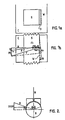
- Figure 6 illustrates a possible alternative or improvement to the oblique contact principle.
- the oblique contact principle relies on the compressive load between wedge 25 and post 1, being carried primarily on the arms of the wedge 25. Since the wedge 25 is resilient there comes a point when the portion of the compressive load carried on the arms 24a and 24b of the wedge represents a small portion of the total compressive force. This is because there is a maximum loading which can be imposed via the arms 24A and 24b i.e. when the wedge 25 has "bottomed" on the post. Additional load from this point on will fall entirely on the middle portion of the wedge 25.
- a notch 21 on the post 1 may be undesirable as it could create a stress point and could limit the possible locations of a clamp member on the post.
- an excessive loading of the type referred to is likely to occur in respect of use of the clamp member in circumstances where it will always be required to be located in one particular position.
- One example of this is in the circumstance where the clamp member 2 is provided as and with an outwardly extending arm or pedal as a foot tread to press a fence post (port 1) into the ground.
- the tooth-notch combination even without the assistance of oblique contact by the arms 24a and 24b of the wedge 24 should provide a workable solution to the problem of removably fixing the collar member to a post where the connectors are subject to extensive loading - e.g. foot pedals on fence posts or heavy shelving.
- the tooth-notch combination could also be reversed.
- the apparatus could be provided as a support member for shelving where the frame is constructed of tubular materials.
- the apparatus could provide a variety of different types of apparatus to connect the wire to the fence post, only one of which has been shown in the drawings.
- the clamp member could be provided as a means of engaging a foot peg on a temporary fence post (as referred to in relation to figure 6).
- a clamp member which is of simple design, and which enables the clamp member to be readily engaged and disengaged from an elongate member.
Landscapes
- Engineering & Computer Science (AREA)
- General Engineering & Computer Science (AREA)
- Mechanical Engineering (AREA)
- Clamps And Clips (AREA)
- Load-Engaging Elements For Cranes (AREA)
- Electrical Discharge Machining, Electrochemical Machining, And Combined Machining (AREA)
- Gripping Jigs, Holding Jigs, And Positioning Jigs (AREA)
Claims (10)
Priority Applications (1)
| Application Number | Priority Date | Filing Date | Title |
|---|---|---|---|
| AT87305136T ATE53439T1 (de) | 1986-06-10 | 1987-06-10 | Klemmvorrichtung. |
Applications Claiming Priority (2)
| Application Number | Priority Date | Filing Date | Title |
|---|---|---|---|
| NZ216465 | 1986-06-10 | ||
| NZ216465A NZ216465A (en) | 1986-06-10 | 1986-06-10 | Clamp with wedging action |
Publications (2)
| Publication Number | Publication Date |
|---|---|
| EP0249459A1 EP0249459A1 (fr) | 1987-12-16 |
| EP0249459B1 true EP0249459B1 (fr) | 1990-06-06 |
Family
ID=19921669
Family Applications (1)
| Application Number | Title | Priority Date | Filing Date |
|---|---|---|---|
| EP87305136A Expired - Lifetime EP0249459B1 (fr) | 1986-06-10 | 1987-06-10 | Dispositif de serrage |
Country Status (7)
| Country | Link |
|---|---|
| US (1) | US4844646A (fr) |
| EP (1) | EP0249459B1 (fr) |
| AT (1) | ATE53439T1 (fr) |
| AU (1) | AU595612B2 (fr) |
| CA (1) | CA1285803C (fr) |
| DE (1) | DE3763100D1 (fr) |
| NZ (1) | NZ216465A (fr) |
Families Citing this family (6)
| Publication number | Priority date | Publication date | Assignee | Title |
|---|---|---|---|---|
| US5509636A (en) * | 1993-08-27 | 1996-04-23 | Cotugno; Joseph A. | Retainer clip for reinforcement of concrete walls |
| US6244581B1 (en) | 2000-02-07 | 2001-06-12 | William J. Arnhold | Wedge clamp |
| US7401754B2 (en) * | 2005-09-12 | 2008-07-22 | Metro Industries, Inc. | Shelf support system having a cylindrical support post and providing improved stability and rigidity |
| DE102009000622A1 (de) * | 2009-02-04 | 2010-08-12 | Alutech Gmbh | Klemmmechanismus und Überrollschutz mit ausfahrbarem Überrollkörper |
| US20150292540A1 (en) * | 2014-04-09 | 2015-10-15 | Natel Energy, Inc. | Wedge clamping system for beams |
| US10954690B1 (en) * | 2018-02-26 | 2021-03-23 | James R. Goff | Pipe fence and method of construction |
Family Cites Families (9)
| Publication number | Priority date | Publication date | Assignee | Title |
|---|---|---|---|---|
| US443627A (en) * | 1890-12-30 | Shaft-coupling | ||
| US1103403A (en) * | 1913-02-11 | 1914-07-14 | Joseph C Duckworth | Key for rotary elements. |
| US1405719A (en) * | 1920-06-02 | 1922-02-07 | John C Reaves | Tappet |
| DE434436C (de) * | 1925-10-13 | 1926-09-22 | Abteilung Diamantwerke | Verbindung einer Lenkstange aus Leichtmetall mit dem Lenkstangenschaft |
| DE671920C (de) * | 1936-05-09 | 1939-02-16 | Alfelder Eisenwerk Otto Wessel | Stellringbefestigung |
| DD112594A3 (fr) * | 1972-10-24 | 1975-04-20 | ||
| DE2428776C2 (de) * | 1974-06-14 | 1983-08-04 | Verin AG, Berneck | Vorrichtung zur lösbaren Halterung einer längenverstellbaren Säule an einer Stuhlsitzplatte, Tischplatte o.dgl. |
| US4214793A (en) * | 1977-07-14 | 1980-07-29 | Gargrave Robert J | Connector and bearing devices |
| DE3246550A1 (de) * | 1982-12-16 | 1984-06-20 | Hetal-Werke Franz Hettich Gmbh & Co, 7297 Alpirsbach | Beschlag zum rechtwinkeligen verbinden von traegern an rohren |
-
1986
- 1986-06-10 NZ NZ216465A patent/NZ216465A/xx unknown
-
1987
- 1987-06-09 AU AU74105/87A patent/AU595612B2/en not_active Ceased
- 1987-06-10 AT AT87305136T patent/ATE53439T1/de not_active IP Right Cessation
- 1987-06-10 US US03/760,281 patent/US4844646A/en not_active Expired - Lifetime
- 1987-06-10 CA CA000539380A patent/CA1285803C/fr not_active Expired - Lifetime
- 1987-06-10 DE DE8787305136T patent/DE3763100D1/de not_active Expired - Lifetime
- 1987-06-10 EP EP87305136A patent/EP0249459B1/fr not_active Expired - Lifetime
Also Published As
| Publication number | Publication date |
|---|---|
| US4844646A (en) | 1989-07-04 |
| DE3763100D1 (de) | 1990-07-12 |
| AU7410587A (en) | 1987-12-17 |
| NZ216465A (en) | 1989-07-27 |
| AU595612B2 (en) | 1990-04-05 |
| ATE53439T1 (de) | 1990-06-15 |
| CA1285803C (fr) | 1991-07-09 |
| EP0249459A1 (fr) | 1987-12-16 |
Similar Documents
| Publication | Publication Date | Title |
|---|---|---|
| US4854764A (en) | Coupling device between two elements | |
| US4730892A (en) | Optical fiber mechanical splice | |
| US4556352A (en) | Shaft-mounted snap lock assembly | |
| US5205057A (en) | Retaining mechanism for a tooth assembly | |
| US6257792B1 (en) | Retaining ring | |
| US4955749A (en) | Swivel connector | |
| EP0172850B1 (fr) | Dispositif de couplage d'un premier organe a un deuxieme organe | |
| US4848870A (en) | Optical fiber jaw connector | |
| US4844646A (en) | Clamp members | |
| EP0308672A1 (fr) | Raccord à dispositif de rétention par ressort | |
| EP0168069A1 (fr) | Raccordement de tuyaux | |
| KR20030085032A (ko) | 샤프트 커플링 | |
| US4569614A (en) | Coupling | |
| EP0180307A1 (fr) | Roue et assemblage roue-axe | |
| US4458927A (en) | Ferrules seals | |
| EP0274235B1 (fr) | Stabilisateur pour train de tiges | |
| CA2137239A1 (fr) | Connecteur a fibres optiques | |
| EP0121629A2 (fr) | Dispositif de fixation pour revêtements de tunnels | |
| US5114264A (en) | Coupling | |
| US4770587A (en) | Locking pin | |
| RU96116955A (ru) | Устройство для направленного бурения | |
| SE461350B (sv) | Anordning foer saekring mot axiell foerskjutning i skarvmuffar vid plastroer | |
| US6779941B2 (en) | Connector device | |
| WO2003024545A1 (fr) | Joint a manchon situe entre le revetement externe et le tubage interne d'un arbre dont la longueur peut etre reglee de maniere telescopique | |
| JPS62233513A (ja) | 2個の部材間の継手装置 |
Legal Events
| Date | Code | Title | Description |
|---|---|---|---|
| PUAI | Public reference made under article 153(3) epc to a published international application that has entered the european phase |
Free format text: ORIGINAL CODE: 0009012 |
|
| AK | Designated contracting states |
Kind code of ref document: A1 Designated state(s): AT BE CH DE ES FR GB GR IT LI LU NL SE |
|
| 17P | Request for examination filed |
Effective date: 19880426 |
|
| 17Q | First examination report despatched |
Effective date: 19880912 |
|
| GRAA | (expected) grant |
Free format text: ORIGINAL CODE: 0009210 |
|
| AK | Designated contracting states |
Kind code of ref document: B1 Designated state(s): AT BE CH DE ES FR GB GR IT LI LU NL SE |
|
| PG25 | Lapsed in a contracting state [announced via postgrant information from national office to epo] |
Ref country code: GR Free format text: LAPSE BECAUSE OF FAILURE TO SUBMIT A TRANSLATION OF THE DESCRIPTION OR TO PAY THE FEE WITHIN THE PRESCRIBED TIME-LIMIT Effective date: 19900606 Ref country code: BE Effective date: 19900606 Ref country code: NL Effective date: 19900606 Ref country code: LI Effective date: 19900606 Ref country code: SE Effective date: 19900606 Ref country code: AT Effective date: 19900606 Ref country code: CH Effective date: 19900606 Ref country code: IT Free format text: LAPSE BECAUSE OF FAILURE TO SUBMIT A TRANSLATION OF THE DESCRIPTION OR TO PAY THE FEE WITHIN THE PRE;WARNING: LAPSES OF ITALIAN PATENTS WITH EFFECTIVE DATE BEFORE 2007 MAY HAVE OCCURRED AT ANY TIME BEFORE 2007. THE CORRECT EFFECTIVE DATE MAY BE DIFFERENT FROM THE ONE RECORDED.SCRIBED TIME-LIMIT Effective date: 19900606 |
|
| REF | Corresponds to: |
Ref document number: 53439 Country of ref document: AT Date of ref document: 19900615 Kind code of ref document: T |
|
| PG25 | Lapsed in a contracting state [announced via postgrant information from national office to epo] |
Ref country code: LU Free format text: LAPSE BECAUSE OF NON-PAYMENT OF DUE FEES Effective date: 19900630 |
|
| REF | Corresponds to: |
Ref document number: 3763100 Country of ref document: DE Date of ref document: 19900712 |
|
| ET | Fr: translation filed | ||
| REG | Reference to a national code |
Ref country code: CH Ref legal event code: PL |
|
| PG25 | Lapsed in a contracting state [announced via postgrant information from national office to epo] |
Ref country code: ES Free format text: LAPSE BECAUSE OF FAILURE TO SUBMIT A TRANSLATION OF THE DESCRIPTION OR TO PAY THE FEE WITHIN THE PRESCRIBED TIME-LIMIT Effective date: 19900917 |
|
| NLV1 | Nl: lapsed or annulled due to failure to fulfill the requirements of art. 29p and 29m of the patents act | ||
| PLBE | No opposition filed within time limit |
Free format text: ORIGINAL CODE: 0009261 |
|
| STAA | Information on the status of an ep patent application or granted ep patent |
Free format text: STATUS: NO OPPOSITION FILED WITHIN TIME LIMIT |
|
| 26N | No opposition filed | ||
| PGFP | Annual fee paid to national office [announced via postgrant information from national office to epo] |
Ref country code: FR Payment date: 19910624 Year of fee payment: 5 |
|
| PGFP | Annual fee paid to national office [announced via postgrant information from national office to epo] |
Ref country code: GB Payment date: 19920608 Year of fee payment: 6 |
|
| PG25 | Lapsed in a contracting state [announced via postgrant information from national office to epo] |
Ref country code: FR Effective date: 19930226 |
|
| REG | Reference to a national code |
Ref country code: FR Ref legal event code: ST |
|
| PG25 | Lapsed in a contracting state [announced via postgrant information from national office to epo] |
Ref country code: GB Effective date: 19930610 |
|
| GBPC | Gb: european patent ceased through non-payment of renewal fee |
Effective date: 19930610 |
|
| PGFP | Annual fee paid to national office [announced via postgrant information from national office to epo] |
Ref country code: DE Payment date: 19990614 Year of fee payment: 13 |
|
| PG25 | Lapsed in a contracting state [announced via postgrant information from national office to epo] |
Ref country code: DE Free format text: LAPSE BECAUSE OF NON-PAYMENT OF DUE FEES Effective date: 20010403 |