EP0249493A2 - Luftfahrzeug-Kollisionswarnsystem - Google Patents
Luftfahrzeug-Kollisionswarnsystem Download PDFInfo
- Publication number
- EP0249493A2 EP0249493A2 EP87305229A EP87305229A EP0249493A2 EP 0249493 A2 EP0249493 A2 EP 0249493A2 EP 87305229 A EP87305229 A EP 87305229A EP 87305229 A EP87305229 A EP 87305229A EP 0249493 A2 EP0249493 A2 EP 0249493A2
- Authority
- EP
- European Patent Office
- Prior art keywords
- aircraft
- antenna
- reply
- antenna units
- interrogating
- Prior art date
- Legal status (The legal status is an assumption and is not a legal conclusion. Google has not performed a legal analysis and makes no representation as to the accuracy of the status listed.)
- Granted
Links
Images


Classifications
-
- G—PHYSICS
- G01—MEASURING; TESTING
- G01S—RADIO DIRECTION-FINDING; RADIO NAVIGATION; DETERMINING DISTANCE OR VELOCITY BY USE OF RADIO WAVES; LOCATING OR PRESENCE-DETECTING BY USE OF THE REFLECTION OR RERADIATION OF RADIO WAVES; ANALOGOUS ARRANGEMENTS USING OTHER WAVES
- G01S13/00—Systems using the reflection or reradiation of radio waves, e.g. radar systems; Analogous systems using reflection or reradiation of waves whose nature or wavelength is irrelevant or unspecified
- G01S13/74—Systems using reradiation of radio waves, e.g. secondary radar systems; Analogous systems
- G01S13/76—Systems using reradiation of radio waves, e.g. secondary radar systems; Analogous systems wherein pulse-type signals are transmitted
-
- G—PHYSICS
- G01—MEASURING; TESTING
- G01S—RADIO DIRECTION-FINDING; RADIO NAVIGATION; DETERMINING DISTANCE OR VELOCITY BY USE OF RADIO WAVES; LOCATING OR PRESENCE-DETECTING BY USE OF THE REFLECTION OR RERADIATION OF RADIO WAVES; ANALOGOUS ARRANGEMENTS USING OTHER WAVES
- G01S13/00—Systems using the reflection or reradiation of radio waves, e.g. radar systems; Analogous systems using reflection or reradiation of waves whose nature or wavelength is irrelevant or unspecified
- G01S13/88—Radar or analogous systems specially adapted for specific applications
- G01S13/93—Radar or analogous systems specially adapted for specific applications for anti-collision purposes
- G01S13/933—Radar or analogous systems specially adapted for specific applications for anti-collision purposes of aircraft or spacecraft
Definitions
- an aircraft collision warning system for use with an aircraft equipped with transponder, as set forth in claim 1 below.
- the system preferably includes alarm means which alert the aircrew when a collision hazard exists, e.g. another aircraft within a range of 5 nautical miles, 9 km.
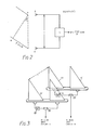
- d ⁇ /d ⁇ (2piS/L) cos ⁇
- the system shown in Fig 1 is essentially a low power IFF interrogator system with an on-board display/warning system to indicate to the aircrew the presence and azimuthal angle of other aircraft in the forward hemisphere.
- the equipment will interrogate Models 1,2,3/A and C in sequence, and any aircraft with an operating transponder that is in range will respond.
- the equipment will be optimized for detection at 10 n miles (18.5 km) range in clear line of sight conditions, and will be programmed to produce warning data of a 'major' threat if a collision is predicted at 5 n miles (9 km) range. This will cater for a worst case situation of two aircraft closing at a combined speed of up to 18 miles a minute (33 km/min), and would give the pilot appoximately 16 seconds in which to react. In different situations with slower closing rates then the reaction time will be correspondingly longer.
- the processed outputs from the equipment produce both visual and audio data.
- the audio data is fed into the aircraft intercom system to give audio warning signals or stored speech messages to the aircrew.
- the visual data can be presented in a variety of formats to suit individual cockpit requirements.
- the processing unit is programmed to present the pilot with simple, easy to assimilate information in a time-frame that will allow any necessary avoiding action to be taken.
- the predicted characteristics of the antenna system are as follows: Azimuth half power beamwidth : 120° Elevation half power beamwidth : 60° Coverage : Azimuth ⁇ 60° Elevation 0-60° Gain : 5.7 dBi Polarization ⁇ Vertical
- the signals received by each antenna are fed through separate channels A and B where they are filtered through stripline bandpass filters 20 and then amplified by low noise amplifiers 21.
- the two signals are then compared in a phase correlator 22.
- This is a stripline device (Fig 5) consisting of four 90° couplers 23 and one fixed 90° phase shifter 24 connected as shown.
- the four outputs from the coupler network are square-law detected by detectors 25 and fed through stripline low-pass filter 26 before feeding to two differential amplifiers 27.
- the outputs of the differential amplifiers are video signals proportional to sin(A - B) and cos(A -B) where (A - B) is the relative phase angle between the two input signals.
- the angular position of the source being a function of the differential phase shift, can thus be determined.
- the warning processor 12 is shown in Fig 6 and utilizes processing devices known in themselves.
- An angle evalutor 28 processes the video sine and cosine signals to provide a 4-bit ANGLE signal.
- a decoder 29 decodes the processed video to derive the 12-bit identifying CODE of the transponder which has replied, a 7-bit RANGE signal and a 2-bit MODE signal.
- the target data thus acquired is fed into a first-in, first-out store 30 to provide data to a microprocessor 31 which can process the stored data in ways well known per se to identify aircraft which are on a potential collision course, provide for display of such aircraft on the display 14 and, when there is a real hazard, activate the audio alarm.
- a logic circuit 32 selects which replies are actually entered in the store 30, first by range selection in response to a range gate 33, secondly in dependence upon a signal from a defruiter 34 which operates in conjunction with its own RAM 35 to signal when there is a correlated transponder reply.
- the transmitter (Fig 7) comprises a master oscillator 36 and pulse modulator 37 which is controlled by consecutive P1, P2 and P3 pulses as is well known in IFF and other secondary radar systems.
- the RF pulses are amplified by an amplifier 38 whose output is fed to the switch 17 (Fig 4).
- the control unit 13 of Fig 1 allows for various operator controls including ON/OFF and selection of interrogation rate.
- the microprocessor 31 of Fig 6 acts in accordance with the selected rate to control an interrogation rate generator 39 (Fig 7) which triggers a mode/stagger generator 40.
- This Mode and Stagger Generator LSI device is controlled by the CPU and generates correctly spaced interrogation pulses P1 and P3, together with the SLS pulse P2, for each mode.
- Stagger is used on the interrogations to prevent the CWS synchronizing with interrogators of other IFF, CWS or ground IFF/SSR systems, and vice versa.
- the low-power of the transmissions used in the CWS is also intended to prevent large scale interference to ground systems by limiting fruit levels.
Landscapes
- Engineering & Computer Science (AREA)
- Radar, Positioning & Navigation (AREA)
- Remote Sensing (AREA)
- Physics & Mathematics (AREA)
- Computer Networks & Wireless Communication (AREA)
- General Physics & Mathematics (AREA)
- Aviation & Aerospace Engineering (AREA)
- Electromagnetism (AREA)
- Radar Systems Or Details Thereof (AREA)
Applications Claiming Priority (2)
| Application Number | Priority Date | Filing Date | Title |
|---|---|---|---|
| GB8614408 | 1986-06-13 | ||
| GB868614408A GB8614408D0 (en) | 1986-06-13 | 1986-06-13 | Aircraft-collision warning system |
Publications (3)
| Publication Number | Publication Date |
|---|---|
| EP0249493A2 true EP0249493A2 (de) | 1987-12-16 |
| EP0249493A3 EP0249493A3 (en) | 1989-01-25 |
| EP0249493B1 EP0249493B1 (de) | 1994-03-02 |
Family
ID=10599412
Family Applications (1)
| Application Number | Title | Priority Date | Filing Date |
|---|---|---|---|
| EP87305229A Expired - Lifetime EP0249493B1 (de) | 1986-06-13 | 1987-06-12 | Luftfahrzeug-Kollisionswarnsystem |
Country Status (3)
| Country | Link |
|---|---|
| EP (1) | EP0249493B1 (de) |
| DE (1) | DE3789167T2 (de) |
| GB (1) | GB8614408D0 (de) |
Cited By (5)
| Publication number | Priority date | Publication date | Assignee | Title |
|---|---|---|---|---|
| US5325302A (en) * | 1990-10-15 | 1994-06-28 | Bvr Technologies, Ltd. | GPS-based anti-collision warning system |
| US6469654B1 (en) * | 2000-05-09 | 2002-10-22 | Advanced Navigation & Positioning Corp. | Transponder landing system |
| GB2381400A (en) * | 2001-08-08 | 2003-04-30 | Ford Global Tech Inc | Integrated radar and active transponder collision avoidance system |
| GB2503902A (en) * | 2012-07-10 | 2014-01-15 | Guidance Navigation Ltd | A locating device |
| US11150334B2 (en) * | 2016-10-13 | 2021-10-19 | Universita' Degli Studi Di Firenze | Bistatic interferometric terrestrial radar with transponder |
Families Citing this family (1)
| Publication number | Priority date | Publication date | Assignee | Title |
|---|---|---|---|---|
| EP2153245A1 (de) * | 2007-05-04 | 2010-02-17 | Teledyne Australia Pty Ltd. | Kollisionsvermeidungssystem und verfahren |
Family Cites Families (9)
| Publication number | Priority date | Publication date | Assignee | Title |
|---|---|---|---|---|
| US2524993A (en) * | 1945-09-14 | 1950-10-10 | Victor H Rumsey | Antenna |
| GB712265A (en) * | 1952-02-14 | 1954-07-21 | Nat Res Dev | Improvements in or relating to aerials |
| US3208064A (en) * | 1957-05-31 | 1965-09-21 | Bendix Corp | Aircraft collision warning system |
| FR1604103A (de) * | 1958-11-07 | 1971-07-12 | ||
| DE1273619B (de) * | 1966-05-28 | 1968-07-25 | Telefunken Patent | Antennensystem fuer eine Sekundaerradaranlage |
| CH474104A (de) * | 1966-12-16 | 1969-06-15 | Siemens Ag Albis | Verfahren und Einrichtung zur Lenkung eines bewegten Körpers zwecks Verhinderung einer Kollision |
| US3750168A (en) * | 1972-04-07 | 1973-07-31 | Nasa | Apparatus for aiding a pilot in avoiding a midair collision between aircraft |
| DE2229193A1 (de) * | 1972-06-15 | 1974-02-14 | Messerschmitt Boelkow Blohm | Antenne fuer schnellfliegende fluggeraete |
| US3851334A (en) * | 1972-09-19 | 1974-11-26 | Us Navy | Collision avoidance and station keeping antenna system |
-
1986
- 1986-06-13 GB GB868614408A patent/GB8614408D0/en active Pending
-
1987
- 1987-06-12 DE DE3789167T patent/DE3789167T2/de not_active Expired - Fee Related
- 1987-06-12 EP EP87305229A patent/EP0249493B1/de not_active Expired - Lifetime
Cited By (7)
| Publication number | Priority date | Publication date | Assignee | Title |
|---|---|---|---|---|
| US5325302A (en) * | 1990-10-15 | 1994-06-28 | Bvr Technologies, Ltd. | GPS-based anti-collision warning system |
| US6469654B1 (en) * | 2000-05-09 | 2002-10-22 | Advanced Navigation & Positioning Corp. | Transponder landing system |
| GB2381400A (en) * | 2001-08-08 | 2003-04-30 | Ford Global Tech Inc | Integrated radar and active transponder collision avoidance system |
| GB2381400B (en) * | 2001-08-08 | 2005-02-16 | Ford Global Tech Inc | An integrated radar and active transponder collision prediction system |
| GB2503902A (en) * | 2012-07-10 | 2014-01-15 | Guidance Navigation Ltd | A locating device |
| GB2503902B (en) * | 2012-07-10 | 2014-06-04 | Guidance Navigation Ltd | A locating device |
| US11150334B2 (en) * | 2016-10-13 | 2021-10-19 | Universita' Degli Studi Di Firenze | Bistatic interferometric terrestrial radar with transponder |
Also Published As
| Publication number | Publication date |
|---|---|
| EP0249493B1 (de) | 1994-03-02 |
| EP0249493A3 (en) | 1989-01-25 |
| GB8614408D0 (en) | 1986-06-13 |
| DE3789167T2 (de) | 1994-09-15 |
| DE3789167D1 (de) | 1994-04-07 |
Similar Documents
| Publication | Publication Date | Title |
|---|---|---|
| US7414567B2 (en) | ADS-B radar system | |
| US5945926A (en) | Radar based terrain and obstacle alerting function | |
| US8130135B2 (en) | Bi-static radar processing for ADS-B sensors | |
| US5400031A (en) | Airport surface vehicle identification system and method | |
| US4128839A (en) | Means for accumulating aircraft position data for a beacon based collision avoidance system and other purposes | |
| US6094169A (en) | Multilateration auto-calibration and position error correction | |
| US6985103B2 (en) | Passive airborne collision warning device and method | |
| US7443334B2 (en) | Collision alerting and avoidance system | |
| US6792058B1 (en) | Digital receiving system for dense environment of aircraft | |
| CA1139410A (en) | Airport-surveillance system | |
| EP1224488B1 (de) | Radarverfahren und vorrichtungen | |
| WO1997043666A9 (en) | Radar based terrain and obstacle alerting function | |
| US5196856A (en) | Passive SSR system utilizing P3 and P2 pulses for synchronizing measurements of TOA data | |
| US4429312A (en) | Independent landing monitoring system | |
| US4107674A (en) | Collision avoidance system for aircrafts | |
| US6545633B1 (en) | Radar system having simultaneous monostatic and bistatic mode of operation | |
| US3626411A (en) | Proximity indicator systems using transponders | |
| CN102227647A (zh) | 用于利用以准动态或动态方式对要监控的空间进行分区化来接收二次雷达信号的设备及用于此的方法 | |
| NO149750B (no) | Radarsystem | |
| US5239310A (en) | Passive self-determined position fixing system | |
| US3582626A (en) | Collision avoidance system which compares relative velocity vector magnitude with range between two craft | |
| EP0249493B1 (de) | Luftfahrzeug-Kollisionswarnsystem | |
| EP1022580A2 (de) | Landungshilfesystem | |
| Malanowski et al. | Passive location system as a combination of PCL and PET technologies | |
| Qiao et al. | Zhang |
Legal Events
| Date | Code | Title | Description |
|---|---|---|---|
| PUAI | Public reference made under article 153(3) epc to a published international application that has entered the european phase |
Free format text: ORIGINAL CODE: 0009012 |
|
| AK | Designated contracting states |
Kind code of ref document: A2 Designated state(s): DE FR GB IT NL |
|
| PUAL | Search report despatched |
Free format text: ORIGINAL CODE: 0009013 |
|
| AK | Designated contracting states |
Kind code of ref document: A3 Designated state(s): DE FR GB IT NL |
|
| 17P | Request for examination filed |
Effective date: 19890214 |
|
| 17Q | First examination report despatched |
Effective date: 19911105 |
|
| GRAA | (expected) grant |
Free format text: ORIGINAL CODE: 0009210 |
|
| ITF | It: translation for a ep patent filed | ||
| AK | Designated contracting states |
Kind code of ref document: B1 Designated state(s): DE FR GB IT NL |
|
| REF | Corresponds to: |
Ref document number: 3789167 Country of ref document: DE Date of ref document: 19940407 |
|
| ET | Fr: translation filed | ||
| PLBE | No opposition filed within time limit |
Free format text: ORIGINAL CODE: 0009261 |
|
| STAA | Information on the status of an ep patent application or granted ep patent |
Free format text: STATUS: NO OPPOSITION FILED WITHIN TIME LIMIT |
|
| 26N | No opposition filed | ||
| PGFP | Annual fee paid to national office [announced via postgrant information from national office to epo] |
Ref country code: NL Payment date: 20010630 Year of fee payment: 15 |
|
| PGFP | Annual fee paid to national office [announced via postgrant information from national office to epo] |
Ref country code: DE Payment date: 20010702 Year of fee payment: 15 |
|
| PGFP | Annual fee paid to national office [announced via postgrant information from national office to epo] |
Ref country code: GB Payment date: 20010704 Year of fee payment: 15 |
|
| PGFP | Annual fee paid to national office [announced via postgrant information from national office to epo] |
Ref country code: FR Payment date: 20010712 Year of fee payment: 15 |
|
| REG | Reference to a national code |
Ref country code: GB Ref legal event code: IF02 |
|
| PG25 | Lapsed in a contracting state [announced via postgrant information from national office to epo] |
Ref country code: GB Free format text: LAPSE BECAUSE OF NON-PAYMENT OF DUE FEES Effective date: 20020612 |
|
| PG25 | Lapsed in a contracting state [announced via postgrant information from national office to epo] |
Ref country code: NL Free format text: LAPSE BECAUSE OF NON-PAYMENT OF DUE FEES Effective date: 20030101 Ref country code: DE Free format text: LAPSE BECAUSE OF NON-PAYMENT OF DUE FEES Effective date: 20030101 |
|
| GBPC | Gb: european patent ceased through non-payment of renewal fee |
Effective date: 20020612 |
|
| PG25 | Lapsed in a contracting state [announced via postgrant information from national office to epo] |
Ref country code: FR Free format text: LAPSE BECAUSE OF NON-PAYMENT OF DUE FEES Effective date: 20030228 |
|
| NLV4 | Nl: lapsed or anulled due to non-payment of the annual fee |
Effective date: 20030101 |
|
| REG | Reference to a national code |
Ref country code: FR Ref legal event code: ST |
|
| PG25 | Lapsed in a contracting state [announced via postgrant information from national office to epo] |
Ref country code: IT Free format text: LAPSE BECAUSE OF NON-PAYMENT OF DUE FEES;WARNING: LAPSES OF ITALIAN PATENTS WITH EFFECTIVE DATE BEFORE 2007 MAY HAVE OCCURRED AT ANY TIME BEFORE 2007. THE CORRECT EFFECTIVE DATE MAY BE DIFFERENT FROM THE ONE RECORDED. Effective date: 20050612 |