EP0249499A2 - Persönliche Anschliessvorrichtung - Google Patents
Persönliche Anschliessvorrichtung Download PDFInfo
- Publication number
- EP0249499A2 EP0249499A2 EP87305255A EP87305255A EP0249499A2 EP 0249499 A2 EP0249499 A2 EP 0249499A2 EP 87305255 A EP87305255 A EP 87305255A EP 87305255 A EP87305255 A EP 87305255A EP 0249499 A2 EP0249499 A2 EP 0249499A2
- Authority
- EP
- European Patent Office
- Prior art keywords
- pin
- lock
- housing
- chain
- barrel
- Prior art date
- Legal status (The legal status is an assumption and is not a legal conclusion. Google has not performed a legal analysis and makes no representation as to the accuracy of the status listed.)
- Withdrawn
Links
- 230000000717 retained effect Effects 0.000 claims abstract description 5
- 239000000463 material Substances 0.000 claims description 2
- 239000004033 plastic Substances 0.000 claims description 2
- 229920003023 plastic Polymers 0.000 claims description 2
- 239000004411 aluminium Substances 0.000 description 1
- 229910052782 aluminium Inorganic materials 0.000 description 1
- XAGFODPZIPBFFR-UHFFFAOYSA-N aluminium Chemical compound [Al] XAGFODPZIPBFFR-UHFFFAOYSA-N 0.000 description 1
- 238000010276 construction Methods 0.000 description 1
- 230000000694 effects Effects 0.000 description 1
- 239000010985 leather Substances 0.000 description 1
- 239000003562 lightweight material Substances 0.000 description 1
- 229910052751 metal Inorganic materials 0.000 description 1
- 239000002184 metal Substances 0.000 description 1
- 238000000034 method Methods 0.000 description 1
- 239000002991 molded plastic Substances 0.000 description 1
- 238000000926 separation method Methods 0.000 description 1
Images

Classifications
-
- E—FIXED CONSTRUCTIONS
- E05—LOCKS; KEYS; WINDOW OR DOOR FITTINGS; SAFES
- E05B—LOCKS; ACCESSORIES THEREFOR; HANDCUFFS
- E05B67/00—Padlocks; Details thereof
- E05B67/003—Chain, wire or cable locks
-
- E—FIXED CONSTRUCTIONS
- E05—LOCKS; KEYS; WINDOW OR DOOR FITTINGS; SAFES
- E05B—LOCKS; ACCESSORIES THEREFOR; HANDCUFFS
- E05B37/00—Permutation or combination locks; Puzzle locks
- E05B37/02—Permutation or combination locks; Puzzle locks with tumbler discs or rings arranged on a single axis, each disc being adjustable independently of the others
-
- Y—GENERAL TAGGING OF NEW TECHNOLOGICAL DEVELOPMENTS; GENERAL TAGGING OF CROSS-SECTIONAL TECHNOLOGIES SPANNING OVER SEVERAL SECTIONS OF THE IPC; TECHNICAL SUBJECTS COVERED BY FORMER USPC CROSS-REFERENCE ART COLLECTIONS [XRACs] AND DIGESTS
- Y10—TECHNICAL SUBJECTS COVERED BY FORMER USPC
- Y10T—TECHNICAL SUBJECTS COVERED BY FORMER US CLASSIFICATION
- Y10T70/00—Locks
- Y10T70/40—Portable
-
- Y—GENERAL TAGGING OF NEW TECHNOLOGICAL DEVELOPMENTS; GENERAL TAGGING OF CROSS-SECTIONAL TECHNOLOGIES SPANNING OVER SEVERAL SECTIONS OF THE IPC; TECHNICAL SUBJECTS COVERED BY FORMER USPC CROSS-REFERENCE ART COLLECTIONS [XRACs] AND DIGESTS
- Y10—TECHNICAL SUBJECTS COVERED BY FORMER USPC
- Y10T—TECHNICAL SUBJECTS COVERED BY FORMER US CLASSIFICATION
- Y10T70/00—Locks
- Y10T70/40—Portable
- Y10T70/413—Padlocks
- Y10T70/417—Combination-controlled
-
- Y—GENERAL TAGGING OF NEW TECHNOLOGICAL DEVELOPMENTS; GENERAL TAGGING OF CROSS-SECTIONAL TECHNOLOGIES SPANNING OVER SEVERAL SECTIONS OF THE IPC; TECHNICAL SUBJECTS COVERED BY FORMER USPC CROSS-REFERENCE ART COLLECTIONS [XRACs] AND DIGESTS
- Y10—TECHNICAL SUBJECTS COVERED BY FORMER USPC
- Y10T—TECHNICAL SUBJECTS COVERED BY FORMER US CLASSIFICATION
- Y10T70/00—Locks
- Y10T70/40—Portable
- Y10T70/413—Padlocks
- Y10T70/417—Combination-controlled
- Y10T70/422—Rigid shackle
- Y10T70/428—Pivoted
- Y10T70/433—Swinging detent
-
- Y—GENERAL TAGGING OF NEW TECHNOLOGICAL DEVELOPMENTS; GENERAL TAGGING OF CROSS-SECTIONAL TECHNOLOGIES SPANNING OVER SEVERAL SECTIONS OF THE IPC; TECHNICAL SUBJECTS COVERED BY FORMER USPC CROSS-REFERENCE ART COLLECTIONS [XRACs] AND DIGESTS
- Y10—TECHNICAL SUBJECTS COVERED BY FORMER USPC
- Y10T—TECHNICAL SUBJECTS COVERED BY FORMER US CLASSIFICATION
- Y10T70/00—Locks
- Y10T70/40—Portable
- Y10T70/413—Padlocks
- Y10T70/487—Parts, accessories, attachments and adjuncts
- Y10T70/491—Shackles
-
- Y—GENERAL TAGGING OF NEW TECHNOLOGICAL DEVELOPMENTS; GENERAL TAGGING OF CROSS-SECTIONAL TECHNOLOGIES SPANNING OVER SEVERAL SECTIONS OF THE IPC; TECHNICAL SUBJECTS COVERED BY FORMER USPC CROSS-REFERENCE ART COLLECTIONS [XRACs] AND DIGESTS
- Y10—TECHNICAL SUBJECTS COVERED BY FORMER USPC
- Y10T—TECHNICAL SUBJECTS COVERED BY FORMER US CLASSIFICATION
- Y10T70/00—Locks
- Y10T70/50—Special application
- Y10T70/5009—For portable articles
- Y10T70/5013—Canes, umbrellas, apparel
Definitions
- This invention relates to apparatus for locking personal items to secure them from theft.
- Many efforts have been made in the past to provide locking devices with which to secure small articles of personal property such as purses, briefcases, coats and skis when circumstances demand that they be left unattended for periods of time.
- a common locking device of this character is a chain and padlock to prevent the theft of an unattended bicycle.
- One device that may be utilized to secure smaller personal articles is shown in U.S. Patent Specification US-A-3,611,760 and consists of a lock and a cable to secure a briefcase to a fixed object. Similar devices are shown in U.S. Patent Specifications US-A-3,906,758 and US-A-4,064,715.
- Bicycle-locking devices are shown in U.S. Patent Specifications US-A-4,490,997 and US-A-4,302,955. Barrel-type combination locks are well known examples are shown in U.S. Patent Specification US-A-1,472,206 and US-A-1,6
- a personal locking device comprising a lock having a housing in which a pin-receiving recess is formed, a lock element slidable within the lock housing, and movable relative to the lock housing between a locked position and an unlocked position, characterized in that a pin housing is fixed on the lock element, a pin is pivotally retained by the pin housing for movement between an open position and a closed position, and the lock element and the lock housing coact with the pin housing so that when the pin is in the closed position on the lock housing and the lock element is in the locked position, the pin is received within the pin-receiving recess to lock the pin in a closed position.
- the locking device of the present invention is convenient and self-contained. It can be used for securing small articles to fixed objects, and is attachable to a large variety of small objects without damage to the objects. It is easily carried in a pocket or purse and can be used when needed.
- FIG. 1 there is shown a personal locking device 10 having a barrel-type combination lock 12 which is conventional in design and therefore will not be described in detail.
- Known barrel-type combination locks are disclosed in U.S. Patent Specifications US-A-1,222,920; 1,267,894; 1,472,206 and 1,627,462.
- the lock 12 is housed in a barrel 14 upon which are received tumbler wheels 16.
- the tumbler wheels have recesses (not shown) so that when the recesses are aligned, the lock is in an open position. When the recesses are not aligned, the lock is locked in a well known manner.
- Each of the tumbler wheels 16 has numerals (not shown) around its circumference so that when the recesses are aligned the numerical combination of the lock appears in alignment on adjacent tumbler wheels in conventional fashion.
- a pin-receving recess is formed in one end of the barrel 14.
- a lock element 20 is positioned in a central bore 21 of the barrel 14 and moves in sliding axial relation to the barrel 14 between the locked position shown in Figure 1 and the unlocked position shown in Figure 2. Again, in conventional fashion, when the tumbler wheels are positioned so that the lock is in the open position, the lock element 20 is freely slidable through the barrel 14.
- the lock element 20 is moved to the position shown in Figure 1. Then the tumbler wheels 16 are rotated. In the locked condition, the tumbler wheels 16 enter recesses 22 formed on the lock element 20 and prevent the lock element from moving.
- Affixed to one end of the lock element 20 is a stop member 24 which is movable towards and away from an annular wall 26 of barrel 14 when the lock element 20 is moved between the open and closed positions shown in Figures 2 and 1 respectively.
- the stop member 24 prevents lock element 20 from being completely withdrawn from the barrel 14.
- a spring 25 surrounds the lock element and abuts at one end against the stop member 24 and at the opposite end against the barrel annular wall 26.
- the spring 25 exerts a force on the stop member 24 to urge the lock element 20 into the barrel bore 21, as shown in Figures 1 and 6.
- the spring 24 is in a compressed position in Figure 2.
- a pin housing 28 of generally cylindrical shape and having a recess 30 formed in it.
- a pin 32 is movably retained on the housing 28 by being pivotally connected to the housing 28 by pivot 34, which is situated in groove 28 a in housing 28.
- the housing 28 also has a pin-receiving groove 36 to receive the free end of pin 32 when the pin 32 is in the closed position as shown in Figure 1.
- Threads 38 are formed on the end of the barrel 14 opposite from the housing 28 to receive a cylindrical chain storage container 40, which has threads 42 that mate with the threads 38, and which is preferably formed from a lightweight material such as a rigid plastics or aluminium. Intead of being threaded at 42 and 38, the container 40 and barrel 14 may be in frictional engagement.
- a chain 44 is provided for use as part of the device and is stored within the container 40 as shown in Figure 1 when the device is not in use.
- the chain 44 is formed from individual interlocking links 46 in conventional fashion.
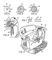
- the chain 44 is a single continuous loop that twice passes through a choke 48 (shown in Figure 7) formed of a body member 50 having a pair of passages 52 through which the chain passes.
- the chain 44 is a selected length having unconnected end portions.
- the choke 48 can be moved along the chain to vary the effective size of the loop of the chain 44.
- the entire device 10 When the device 10 is in the locked position and the chain 44 is stored within the container 40 as shown in Figure 1, the entire device 10 has an overall length of approximately seven inches (175mm) and has a diameter of approximately one inch (25 mm). It is lightweight and may be readily carried in the purse or pocket of the user until needed.
- Figure 8 illustrates one example of use of the device 10, viz to lock a garment, (shown as a zip-fastened coat 54) to a wall hook 56.
- a garment shown as a zip-fastened coat 54
- First one end of the loop chain 44 is wrapped tightly around the hook 56.
- the choke 48 is advanced on the chain 44 to close the loop of the chain 44 tightly around the hook 56.
- the coat 54 is then secured to the chain 44 by passing the unlocked pin 32 through the hole in the puller of slide block 58 of zip-fastener 60.
- the pin 32 is then inserted, as above described, in the barrel recess 14 to lock the pin 32 in the closed position.
- the chain 44 is locked to both the coat 54 and the hook 56.
- Figure 9 illustrates a similar example of use of the locking device 10 to secure a handbag 62 to an arm 64 of a chair 66.
- the chain 44 is looped around the arm 64 and through itself to form a noose 68 around the arm 64.
- the choke 48 is left free to slide on the chain 44 because the noose 68 around the chair arm 64 prevents separation of the chain 44 from the chair 66.
- the locking device 10 is then secured to the handbag 62 by passing the open pin 32 through an aperture in a closure element 70 of the handbag 62.
- the element 70 extends through an opening 72 of a flap 74 of the handbag 62 to close the handbag.
- the locking device of the invention can be used to secure various types of small articles, not merely handbags and garments, to various types of fixed objects. It may be possible to secure more than one article using a single locking device.
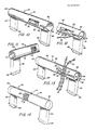
- Figures 10 to 14 illustrate an embodiment of the invention in which the locking device 10 is integrally incorporated in a member such as a luggage handle 76 to facilitate securing the associated luggage to a stationary object.
- the luggage handle 76 is specifically adapted for use with the locking device 10 even though the handle 76 is substantially conventional in design. As seen in Figures 10 and 11, the handle 76 includes an elongated tubular body portion 78 supported, adjacent to opposite ends 80 and 82, by integral posts 84 and 86. The extreme ends of the posts receive pins 88 by which the handle is conventionally secured to the frame of a pice of luggage such as a suitcase, briefcase or purse (not shown).
- the body portion 78 may be selectively fabricated. For example it can be moulded plastics, metal cast, all-leather or a combination of these and other suitable materials.
- the body portion 78 is preferably formed with the end 80 closed and the end 82 open to receive the entire locking device 10 with the storage container 40 attached to the barrel 14 in a cavity 83.
- aperture 90 which is shown completely in Figure 10, is positioned to expose the connection of the pin 32 in the pin-receiving recess 18 of the barrel 13.
- the aperture 90 is large enough to permit movement of the pin 32 into and out of locked position as shown in Figures 12 and 13.
- the aperture 92 which is completely in Figures 11 and 14, is positioned on the opposite side of the body portion 78 to expose the tumbler wheels 16 of the combination lock 12 when the lock 12 is in an operative position within the cavity 83 of the body portion 78.
- the wheels 16 are exposed to permit manipulation of the wheels for unlocking the pin 32 from the barrel recess 18.
- an elongated slot 94 that extends from an opening 96 at end 82 to a closed end portion 98, which is close to the aperture 90.
- the slot 94 receives the pin 32 as the lock is advanced into the cavity 96. With this arrangement, the pin 32 extends out of the cavity 83 and overlies the body portion 78. The free end of the pin 32 overlies the aperture 90 for pivotal movement into and out of engagement with the aligned groove 36 and recess 18 so as to lock and unlock the locking device 10 to the luggage handle 76.
- the chain 44 is used with the pin 32 as above described. With the pin 32 in the open position shown in Figure 12, selected links 46 of the chain 44 are positioned on the pin 32. Thereafter the pin 32 is moved to the closed postion shown in Figure 13 to lock the chain 44 to the locking device 10. This has the effect of locking the chain 44 to the handle 76 and the associated luggage. Thus a convenient arrangement is available for securing the luggage by the locking device 10 to a stationary object. At the same time, the locking device 10 becomes an integral part of the luggage.
- the locking device 10 is always conveniently available for use on the handle 76.
- the chain 44 is stored in the container 40 and the locking device 10 is, in turn, locked to the handle 76, thus preventing removal of the device 10 from the handle 76.
- a variety of methods can be used as above discussed in order to secure the chain 44 to a stationary object.
Landscapes
- Purses, Travelling Bags, Baskets, Or Suitcases (AREA)
- Lock And Its Accessories (AREA)
Applications Claiming Priority (2)
| Application Number | Priority Date | Filing Date | Title |
|---|---|---|---|
| US874220 | 1986-06-13 | ||
| US06/874,220 US4682481A (en) | 1986-06-13 | 1986-06-13 | Personal locking device |
Publications (2)
| Publication Number | Publication Date |
|---|---|
| EP0249499A2 true EP0249499A2 (de) | 1987-12-16 |
| EP0249499A3 EP0249499A3 (de) | 1988-08-03 |
Family
ID=25363252
Family Applications (1)
| Application Number | Title | Priority Date | Filing Date |
|---|---|---|---|
| EP19870305255 Withdrawn EP0249499A3 (de) | 1986-06-13 | 1987-06-12 | Persönliche Anschliessvorrichtung |
Country Status (3)
| Country | Link |
|---|---|
| US (1) | US4682481A (de) |
| EP (1) | EP0249499A3 (de) |
| AU (1) | AU592460B2 (de) |
Cited By (1)
| Publication number | Priority date | Publication date | Assignee | Title |
|---|---|---|---|---|
| GB2263135A (en) * | 1992-01-07 | 1993-07-14 | James Thomas Hardy Cooke | Anti-theft security device for hand luggage |
Families Citing this family (11)
| Publication number | Priority date | Publication date | Assignee | Title |
|---|---|---|---|---|
| US4805426A (en) * | 1987-07-27 | 1989-02-21 | Lockman Products Company, Inc. | Locking device |
| US5701769A (en) * | 1996-05-30 | 1997-12-30 | Hall; Jeffrey D. | Grasping apparatus and method |
| US6227015B1 (en) * | 1999-03-11 | 2001-05-08 | L. Hanson Luquire | Padlock |
| US20040050123A1 (en) * | 2002-05-29 | 2004-03-18 | Stamatina Macherides | Quick release key ring assembly for portable electronic device housings and adaptors thereto |
| US20050288082A1 (en) * | 2004-06-15 | 2005-12-29 | Carlos De La Huerga | Word puzzle assembly and methods related thereto |
| US20050278186A1 (en) * | 2004-06-15 | 2005-12-15 | Carlos De La Huerga | Word puzzle assembly and methods related thereto |
| TWM271062U (en) * | 2004-12-21 | 2005-07-21 | Sinox Co Ltd | Padlock |
| US7866505B2 (en) * | 2005-10-06 | 2011-01-11 | Blue Chip Group, Llc | Portable and lockable storage container |
| TW201043768A (en) * | 2009-06-06 | 2010-12-16 | Chun-Te Yu | Detachable dual lock |
| FR2951570B1 (fr) * | 2009-10-19 | 2012-06-29 | Thoonsen Trading | Dispositif antivol pour articles de vente |
| DE102020115761A1 (de) * | 2020-06-15 | 2021-12-16 | ABUS August Bremicker Söhne Kommanditgesellschaft | Kettenschloss |
Family Cites Families (22)
| Publication number | Priority date | Publication date | Assignee | Title |
|---|---|---|---|---|
| US599765A (en) * | 1898-03-01 | Permutation-lock | ||
| US200990A (en) * | 1878-03-05 | Improvement in padlocks | ||
| DE72960C (de) * | J. BORNI in Hamburg, Alsterstr. 30 | Vorrichtung zur Feststellung einer Kettenschleife in beliebiger Weite | ||
| US486256A (en) * | 1892-11-15 | And james o connell | ||
| US1025284A (en) * | 1911-10-11 | 1912-05-07 | Julius Mikkelsen Lybeck | Lock attachment. |
| US1222920A (en) * | 1913-08-20 | 1917-04-17 | William E Blais | Combination-lock. |
| US1267894A (en) * | 1916-10-28 | 1918-05-28 | Lars Olson | Lock. |
| US1423840A (en) * | 1921-05-18 | 1922-07-25 | Joseph F Maday | Permutation padlock |
| US1472206A (en) * | 1922-10-24 | 1923-10-30 | Burkle William | Combination chain lock |
| US1477777A (en) * | 1922-11-29 | 1923-12-18 | Frank P Shek | Lock |
| US1632338A (en) * | 1925-05-01 | 1927-06-14 | Horton Edwin | Pin fastener |
| US1627462A (en) * | 1926-01-06 | 1927-05-03 | Rohmer Frank Daniel | Combination lock |
| US1857399A (en) * | 1930-01-13 | 1932-05-10 | Piagneri Umberto | Permutation lock |
| US3611760A (en) * | 1970-01-12 | 1971-10-12 | Muther Enterprises Inc | Locking device |
| US3906758A (en) * | 1974-07-29 | 1975-09-23 | Ronald Hurwitt | Combination cable lock |
| US4064715A (en) * | 1977-01-24 | 1977-12-27 | International Power Pole, Ltd. | Anti-theft device |
| US4185361A (en) * | 1978-04-26 | 1980-01-29 | Stuart Robert B | Locking device |
| US4302955A (en) * | 1979-04-04 | 1981-12-01 | Shigeru Kawakami | Bicycle lock |
| US4398403A (en) * | 1981-10-30 | 1983-08-16 | Menick Douglas B | Compact, portable locking mechanism |
| US4597273A (en) * | 1983-03-11 | 1986-07-01 | Reichenberger Arthur M | Security device |
| US4490997A (en) * | 1983-04-25 | 1985-01-01 | Hughes Leland G | Bicycle locking device |
| US4543806A (en) * | 1983-07-18 | 1985-10-01 | James J. Papandrea | Retractable cable lock |
-
1986
- 1986-06-13 US US06/874,220 patent/US4682481A/en not_active Expired - Fee Related
-
1987
- 1987-06-12 EP EP19870305255 patent/EP0249499A3/de not_active Withdrawn
- 1987-07-14 AU AU75623/87A patent/AU592460B2/en not_active Ceased
Cited By (1)
| Publication number | Priority date | Publication date | Assignee | Title |
|---|---|---|---|---|
| GB2263135A (en) * | 1992-01-07 | 1993-07-14 | James Thomas Hardy Cooke | Anti-theft security device for hand luggage |
Also Published As
| Publication number | Publication date |
|---|---|
| AU592460B2 (en) | 1990-01-11 |
| AU7562387A (en) | 1989-01-19 |
| EP0249499A3 (de) | 1988-08-03 |
| US4682481A (en) | 1987-07-28 |
Similar Documents
| Publication | Publication Date | Title |
|---|---|---|
| US4805426A (en) | Locking device | |
| US4792026A (en) | Apparatus for locking a carrying case | |
| US5517835A (en) | Cable locking device | |
| US11717062B2 (en) | Interlocking zipper pull tabs and fastening system | |
| US5460022A (en) | Concealed handcuff key | |
| US4682481A (en) | Personal locking device | |
| US4756171A (en) | Luggage lock system | |
| US7891220B2 (en) | Multi-purpose detachable lock container and method of use | |
| US3611760A (en) | Locking device | |
| US4811577A (en) | Portable locking device | |
| US4733549A (en) | Theft preventing luggage handle attachment | |
| US20080072633A1 (en) | Security device | |
| US6786372B2 (en) | Belt clip apparatus for portable electronic device | |
| ES8101182A1 (es) | Dispositivo de cerradura principalmente para maleta | |
| CN103930637A (zh) | 用于行李箱的多重锁定系统 | |
| US7080530B2 (en) | Keyless locking device | |
| US4817403A (en) | Personal locking device | |
| GB2290284A (en) | Baggage | |
| US3394959A (en) | Lock for handbag clasp | |
| US6148993A (en) | Key-concealing pouch for carrying small articles | |
| CA1294143C (en) | Personal locking device | |
| KR102684113B1 (ko) | 도난방지용 가방 | |
| EP0447477B1 (de) | Anordnung zum verschluss von kleidern, säcken, schuhen, usw. | |
| JP2001512328A (ja) | 同時に操作される少なくとも3個のフック手段で閉鎖される鞄 | |
| CA2175291A1 (en) | A suitcase or similar receptacle |
Legal Events
| Date | Code | Title | Description |
|---|---|---|---|
| PUAI | Public reference made under article 153(3) epc to a published international application that has entered the european phase |
Free format text: ORIGINAL CODE: 0009012 |
|
| AK | Designated contracting states |
Kind code of ref document: A2 Designated state(s): BE CH DE FR GB IT LI NL SE |
|
| PUAL | Search report despatched |
Free format text: ORIGINAL CODE: 0009013 |
|
| AK | Designated contracting states |
Kind code of ref document: A3 Designated state(s): BE CH DE FR GB IT LI NL SE |
|
| 17P | Request for examination filed |
Effective date: 19890131 |
|
| 17Q | First examination report despatched |
Effective date: 19891005 |
|
| STAA | Information on the status of an ep patent application or granted ep patent |
Free format text: STATUS: THE APPLICATION IS DEEMED TO BE WITHDRAWN |
|
| 18D | Application deemed to be withdrawn |
Effective date: 19920902 |
|
| RIN1 | Information on inventor provided before grant (corrected) |
Inventor name: DIMMICK, GARY S. Inventor name: LOCKERMAN, SCOTT G. |