EP0249523A1 - Verfahren und Vorrichtung zum Betrieb eines Thermodruckkopfes - Google Patents
Verfahren und Vorrichtung zum Betrieb eines Thermodruckkopfes Download PDFInfo
- Publication number
- EP0249523A1 EP0249523A1 EP87401197A EP87401197A EP0249523A1 EP 0249523 A1 EP0249523 A1 EP 0249523A1 EP 87401197 A EP87401197 A EP 87401197A EP 87401197 A EP87401197 A EP 87401197A EP 0249523 A1 EP0249523 A1 EP 0249523A1
- Authority
- EP
- European Patent Office
- Prior art keywords
- heating
- duration
- cycles
- cycle
- during
- Prior art date
- Legal status (The legal status is an assumption and is not a legal conclusion. Google has not performed a legal analysis and makes no representation as to the accuracy of the status listed.)
- Granted
Links
- 238000000034 method Methods 0.000 title claims description 23
- 238000007651 thermal printing Methods 0.000 title description 5
- 238000007639 printing Methods 0.000 claims abstract description 23
- 238000010438 heat treatment Methods 0.000 claims description 135
- 238000006073 displacement reaction Methods 0.000 claims description 7
- 238000001816 cooling Methods 0.000 claims description 5
- 230000001960 triggered effect Effects 0.000 claims 1
- 238000012545 processing Methods 0.000 abstract description 2
- 238000010586 diagram Methods 0.000 description 8
- 230000000630 rising effect Effects 0.000 description 5
- 230000008569 process Effects 0.000 description 4
- 230000008646 thermal stress Effects 0.000 description 4
- 238000011144 upstream manufacturing Methods 0.000 description 4
- 239000004020 conductor Substances 0.000 description 3
- 238000013461 design Methods 0.000 description 2
- 238000007493 shaping process Methods 0.000 description 2
- 238000010023 transfer printing Methods 0.000 description 2
- 238000013459 approach Methods 0.000 description 1
- 230000005540 biological transmission Effects 0.000 description 1
- 230000008859 change Effects 0.000 description 1
- 230000008878 coupling Effects 0.000 description 1
- 238000010168 coupling process Methods 0.000 description 1
- 238000005859 coupling reaction Methods 0.000 description 1
- 230000001186 cumulative effect Effects 0.000 description 1
- 230000006378 damage Effects 0.000 description 1
- 230000001934 delay Effects 0.000 description 1
- 238000010017 direct printing Methods 0.000 description 1
- 235000021183 entrée Nutrition 0.000 description 1
- 230000006870 function Effects 0.000 description 1
- 230000006872 improvement Effects 0.000 description 1
- 230000007257 malfunction Effects 0.000 description 1
- 238000002844 melting Methods 0.000 description 1
- 230000008018 melting Effects 0.000 description 1
- 230000000737 periodic effect Effects 0.000 description 1
- 230000005855 radiation Effects 0.000 description 1
- 230000009467 reduction Effects 0.000 description 1
- 230000004044 response Effects 0.000 description 1
- 238000012549 training Methods 0.000 description 1
- 238000012546 transfer Methods 0.000 description 1
Images


Classifications
-
- B—PERFORMING OPERATIONS; TRANSPORTING
- B41—PRINTING; LINING MACHINES; TYPEWRITERS; STAMPS
- B41J—TYPEWRITERS; SELECTIVE PRINTING MECHANISMS, i.e. MECHANISMS PRINTING OTHERWISE THAN FROM A FORME; CORRECTION OF TYPOGRAPHICAL ERRORS
- B41J2/00—Typewriters or selective printing mechanisms characterised by the printing or marking process for which they are designed
- B41J2/315—Typewriters or selective printing mechanisms characterised by the printing or marking process for which they are designed characterised by selective application of heat to a heat sensitive printing or impression-transfer material
- B41J2/32—Typewriters or selective printing mechanisms characterised by the printing or marking process for which they are designed characterised by selective application of heat to a heat sensitive printing or impression-transfer material using thermal heads
- B41J2/35—Typewriters or selective printing mechanisms characterised by the printing or marking process for which they are designed characterised by selective application of heat to a heat sensitive printing or impression-transfer material using thermal heads providing current or voltage to the thermal head
- B41J2/355—Control circuits for heating-element selection
Definitions
- the present invention firstly relates to a method of controlling a print head, or writing, thermal, of the serial type, for a printing system, in particular for a printer connected to a word processing device. .
- a thermal writing head generally comprises a plurality of heating elements, in general resistive elements arranged to be traversed by a current, and to cooperate either directly with a printing medium, heat-sensitive paper, or indirectly with a medium.
- ordinary printing by means of a ribbon coated with an ink melting with the heat of the elements. In the first case, it is a direct thermal printing, in the second case, a thermal transfer printing.
- the movable head comprises at least one bar, generally vertical, of elements, aligned in a direction orthogonal to the direction of rectilinear displacement, during the printing of a line of graphics, corresponding to the height of the bar, of a head support carriage.
- the set of heating elements that are heated during the same cycle obviously depends on the configuration of the transverse section of the line to be printed, of dimension L, equal to the product of the speed of displacement by the duration T of the cycles.
- the vertical definition depends only on the size and the spacing of the heating elements of the writing head.
- the horizontal definition is approximately inversely proportional to the speed of training of the head.
- the thermal inertia of a heating element it is not possible to make the interval of time during which it is hot enough to print as small as desired. This time interval is therefore bounded by a lower limit, the horizontal dimension of the "point" that it prints is therefore substantially inversely proportional to the speed of drive of the head.
- the present invention aims to provide a better compromise, that is to say, at constant writing speed, better horizontal definition or, with equivalent horizontal definition, greater writing speed.
- the present invention relates to a method of the type defined above, characterized in that the duration of the cycles is chosen at most equal to the duration of printing of the dots and that some of the heating elements are subjected to heating for a period starting in the middle of the cycles.
- the invention pre therefore sees being able to subject it, within the same cycle to a second heating.
- the heating element When the heating element is subjected to two successive heatings during the same cycle, it prints an "extended point".
- the start of this extended point coincides with the start of a normal point, but its length is greater than that of the normal point.
- the invention provides that it can only be subjected to heating from the middle of the cycle.
- the heating element prints an offset point.
- the start of this offset point is offset by half the width of a slice with respect to a normal point.
- the initial heating time and the heating time starting in the middle of the cycle are less than half the duration of a cycle.
- the offset point has the same length as the normal point and the extended point a length substantially equal to one and a half times the length of the normal point.
- the possible offset being equal to half a normal point length, we can say that we obtain a "pseudoresolution" double of the original resolution.
- a true double resolution would indeed suppose that the length of the point is divided by two, which is not the case.
- the duration (TI) of heating, during a first half-cycle, of a heating element determined is modulated so as to shorten this duration if this heating element has been heated during one of the two preceding half-cycles, and modulating the duration (TID) of heating, during a second half-cycle, of a determined heating element so as to shorten this duration if this heating element has been heated during one of the three preceding half-cycles.
- the writing head is provided with a first bar and a second transverse bar arranged one after the other in the longitudinal direction, and in which, at during an odd-order cycle, the heating elements of the second strip are not subjected to any heating, and, during an even-order cycle, the heating elements of the first strip are not subjected to any heating .
- a thermal print head 14 of serial type to print a line of characters 10 using a thermal print head 14 of serial type, the head 14 is moved in longitudinal displacement , here horizontal, along the line to be printed 10, in the direction of arrow 15, using a drive device which is not shown because it is conventional.
- Line 10 is broken down into a series of transverse sections 10a, 10b, ..., 10m, ... whose horizontal dimension is equal to the horizontal dimension, or length, L of an elementary point 100 that each of the heating elements 140 when it heats.
- the heating elements 140 are distributed along a transverse bar, here vertical, the height of which corresponds so at the height of the laundry 10.
- each section 10m is printed during a writing cycle the duration T of which is equal to the length L of a point 100, divided by the drive speed of the head 14.
- Each of the heating elements 140 is here a resistive element, accessible individually by connections not shown in FIG. 1, for the sake of simplicity. We will now describe the method of controlling one of these heating elements 140, the task of which is obviously to print a series of dots whose configuration depends on the line to be printed.
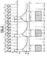
- each writing cycle of duration T is divided into two half-cycles of duration T / 2. It is expected to be able to heat, at the start of each half-cycle, the heating element considered for a duration TI for each first half-cycle and for a duration TID for each second half-cycle.
- the heating element is heated here by passing it through a current I so that, taking into account its thermal inertia, after heating for the duration TI or for the duration TID, its temperature 0 remains above a temperature of threshold 6 s for a time equal to T.
- the threshold temperature ⁇ s is that above which the paper is printed, the point printed by the heating element heated for a period TI or TID corresponds to the length L.
- the TI and TID durations of the heating phases are modulated so as to shorten them if the heated element is still hot at the start of each of these phases.
- the duration TI of heating during a first half-cycle takes the value T1 if the heating element has not been heated during any of the two half-cycles preceding this first half cycle; otherwise, the duration TI takes the value T2, with:
- the duration TID of heating during a second half-cycle takes the value TID if the heating element has not been heated during any of the three half-cycles preceding this second half-cycle; otherwise, the duration TID takes the value T2D, with:
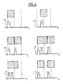
- FIG. 4 shows, by way of example, a certain number of configurations to be printed and the shape of the heating current I.
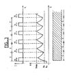
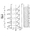
- FIG. 5 shows the result obtained in the case analogous to that of FIG. 3, of the writing of an uninterrupted series of normal points. It shows that the temperature remains below the maximum temperature ⁇ max .
- the writing head 14 being provided with a plurality of heating elements 140 distributed on a vertical bar, at each first half-cycle of a cycle, a first set of points is heated which corresponds to the configuration of the first half-section of the section to be written corresponding to the cycle considered, and each second half-cycle, a second set which corresponds to the configuration of the second half-section.
- the thermal stresses on the elements heating elements are quite severe, in particular when writing a continuous horizontal line where the temperature 6 must remain permanently above the writing threshold ⁇ s .
- the life of the heating elements, and therefore of the head is relatively short.
- the first strip 141 is active during write cycles of odd order, while it is at rest during write cycles of even order.
- the second strip 142 is active during write cycles of even order, and at rest during write cycles of odd order. That is to say that the first strip 141 prints only the odd-order sections, while the second strip 142 prints only the even-order sections.
- the writing is only complete after the passage of the two bars.
- the part common to the offset point and to the normal point does not present any difference in shade because all of the ink of the heat-sensitive paper, in the case of direct printing, or of the ribbon stationary relative to the paper, in the case of transfer printing, is released by the first heating element.
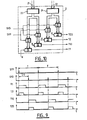
- the device shown in FIG. 8 is used, which receives on a bus 161 the data to be printed in the form of a digital signal and which controls the resistive elements 140 of the head 14 , including here a single bar of J elements.
- a clock 1 of known type delivers on three outputs three clock signals SYP, SYD and H.
- a sequence generator 2 receives the three signals SYP, SYD and H on three binary inputs and two digital signals, via two buses 21 and 22, on two digital inputs. It delivers on four binary outputs four sequential signals T1, T1D, T2 and T2D.
- a decoder circuit 16 receives the coded data in digital form, via the bus 161, on a digital input, as well as the signal SYP on a binary input. It delivers two groups of J binary output signals on two buses 31 and 32 of type parallel to J bits, that is to say each comprising J parallel conductors.
- a delay circuit 3 receives the signal SYP on a binary input and is connected to buses 31 and 32.
- the delay circuit 4 delivers three groups of J binary output signals tie on three buses 41, 42 and 43, of type parallel to J bits.
- a multiplexer 4 of known type, of which a digital control input is connected to the digital output of a counter 6 receives the signals from the three buses 41, 42 and 43, and delivers three binary output signals on three outputs 71, 72 and 73.
- the counter 6 is a modulo J counter, of known type, whose clock input receives the signal H and whose reset input receives the output signal from a detector 5 of the rising edges of the sequential signals T1, T1D, T2 and T2D, which it receives on four binary inputs.
- the counter 6 delivers a signal D on its overflow output.
- a circuit 7 for calculating the information to be printed is provided with three binary inputs connected to outputs 71, 72 and 73, and four binary inputs receiving the sequential signals T1, T1D, T2 and T2D. It delivers, on two binary outputs, two INF and CE output signals.
- a register 8 of the known type with serial input and parallel output at J bits, receives on a clock input, the signal H after passing through a logic gate 9 controlled by the signal D.
- the J conductors of the parallel output of the register 8 are connected to a buffer register 10 with parallel input and output, controlled by the signal D after passing through a shaping circuit 11.
- J conductors of the parallel output of register 10 are connected to J AND gates 12 of which the J other inputs receive the signal CE.
- each AND gate 12 is connected to the control input of a controllable switch 13 disposed between a first terminal of a supply circuit 150 delivering the voltage VP and a terminal of one of the J resistive heating elements 140, the other terminal of which is connected to the second terminal of the supply circuit 150.
- the supply circuit 150 also supplies electrical energy to all the elements of the preceding circuits, in a manner not shown for the sake of simplicity.
- Clock 1 delivers the signals SYP and SYD represented in FIG. 9, that is to say pulse trains with a frequency of recurrence equal to 1 / T and offset with respect to each other by T / 2.
- the signal H not shown, is a train of pulses like the signals SYP and SYD, but of much higher recurrence frequency.
- the sequential signals T1, T1D, T2 and T2D have the appearance shown in FIG. 9.
- the signals T1 and TID are at the high level for equal durations offset by T / 2, like the signals T2 and T2D.
- the duration of the sequence at the high level of the signal T2 is less than the duration of the sequence at the high level of the signal T1.
- the T1 and T2 signals go high during each pulse of the SYP signal.
- the TID and T2D signals go high on each pulse of the SYD signal.
- the decoder circuit 16 develops, as a function of the data it receives on the bus 161, two groups of J binary signals which possibly change with each pulse of the signal SYP.
- the J binary signals of the first group are:
- the J binary signals of the second group are:
- J type signals are transported by bus 31 and the J signals of the type are transported by bus 32.
- the delay circuit 3 delays these signals to deliver the three groups of J signals of the type , , and on the three buses 41, 42 and 43, respectively.
- the counter 6 After each rising edge of one of the sequential signals T1, T1D, T2 and T2D detected by the rising edge detector 5, the counter 6 is reset and controls, at the rate of the clock signal H the time multiplexing of the buses 41, 42 and 43 on binary outputs 71, 72 and 73.
- the circuit 7 for calculating the information to be printed calculates a binary signal INF which is at the high level if the heating element of rank j is to be heated and at the low level otherwise, for each of the four time intervals T2, (T1-T2), T2D, (T2D-T1D) of the range of rank (i - 1), so as to heat during time T1 or time T2, and during time TID or time T2D, depending, on the one hand, of the command for the range of rank (i - 1), and on the other hand of the state passed during the range of rank (i - 2) of this element, in accordance with the method described.
- the calculation circuit 7, from the seven signals applied to it, , , , T1, T1D, T2, T2D calculates the signal INF for the element of rank j as follows:
- the J values of the signal INF calculated one after the other by the calculation circuit 7 are stored in the series-parallel register 8, after each rising edge of one of the sequential signals T1, T1D, T2 and T2D , then transferred to the buffer register 10 which controls, via the AND gates 12, the heating of the heating elements 14.
- the AND gates cannot be turned on if the CE signal is at the high level.
- This signal CE is produced by the calculation circuit 7 to be at the low level when the signal T1 and the signal T1D are normally at the low level, so as to ensure, even in the event of a malfunction of the circuits placed upstream of the doors 12, for example if T1 or TID remain at the high level at the end of the current half-cycle, periodic cooling of the heating elements to avoid destruction.
- the current I which flows in each heating element 14 is here equal to the voltage VP divided by the value of the resistance of a heating element.
- the constitution of the sequence generator is shown in FIG. 10.
- Two registers 23 and 24 receive the digital signals present on the buses 21 and 22 which, as will be seen below, control the durations of the signals T 1 and TID of on the one hand and T2 and T2D on the other.
- the output of register 23 is applied to two gate circuits 25 controlled by the signals SYP and SYD.
- the output of register 24 is applied to two gate circuits 25, controlled by the signals SYP and SYD.
- Four counters 26, each provided with a clock input receiving the signal H and a parallel input receiving the output of one of the gates 25 deliver, on their four sign outputs, the signals T1, T1D, T2 and T2D .
- circuit 2 The operation of circuit 2 is as follows. Each counter 26 is mounted as a down-counter and its sign output is therefore positive, after having been loaded at the digital output value of the corresponding gate 25, only for a time which depends on this digital value.
- the signals shown in FIG. 9 are therefore obtained, the digital signal on the bus 21 controlling the duration, equal, of the signals T1 and TID and the digital signal on the bus 22 controlling the duration, equal, of the signals T2 and T2D.
- These durations can therefore be adjusted by the operator to adapt the device to the characteristics of the heating elements of the writing head, by modifying the digital signals applied to the buses 21 and 22.
- the decoder circuit 16 includes a memory which contains the different bit sequences and corresponding to the various alphanumeric characters to be written, the print quality of which will obviously be better, taking into account the particular possibilities of the process of the invention of printing an offset point and an extended point.
- This memory is addressed by addressing circuits of known type, in response to the coded data received on the bus 161.
- the decoder circuit is therefore of known type, within the reach of those skilled in the art and will not be described further.
- the delay circuit 3 is shown in FIG. 11. It comprises on the one hand three buffer registers 34, 35 and 36 connected in cascade between the bus 31 and the bus 42 and on the other hand two buffer registers 37 and 38 connected in cascade between bus 32 and bus 43.
- a shaping circuit 330 the input of which receives the signal SYP, delivers at the output a signal which controls, on the one hand, a circuit of doors 333 interposed upstream of the register 36, and on the other hand, and after passing through a delay line 331, two gate circuits 332 each interposed upstream of the registers 35 and 38.
- the delay of the delay line 331 corresponds to the time necessary to transfer the data from one register like register 34 to the next like register 35, via a circuit of doors 332.
- the bus 41 is connected in bypass to the output of register 35, upstream of door 333. The operation of a such a circuit is obvious to those skilled in the art.
- the rising edge detector 5, as well as the circuit 7 for calculating the information to be printed, are entirely conventional combinational logic circuits, the design of which is within the reach of those skilled in the art, and will not be further described.
- each of the bars is controlled by a device identical to that of FIG. 8, except that a single decoder 16, common to the two devices, is used .
- the heating current I of the resistive elements is constant and its duration of application variable.
- the durations of the sequences at the high level of the signals T1 and TID on the one hand, T2 and T2D on the other hand are equal. Furthermore, these durations are less than the duration T / 2 of a half-cycle.
- the durations of the sequences at the high level of the signals T1, T1D, T2 and T2D can be chosen as desired, while remaining less than the duration T of a cycle, in the cases where the head can withstand the resulting thermal stresses and where we don't try to get points of constant length.
- heating system by current flow in a resistive element can be replaced by any other heating system, for example by radiation, which may be suitable for thermal printing.
Landscapes
- Electronic Switches (AREA)
Applications Claiming Priority (2)
| Application Number | Priority Date | Filing Date | Title |
|---|---|---|---|
| FR8608125 | 1986-06-05 | ||
| FR8608125A FR2599672A1 (fr) | 1986-06-05 | 1986-06-05 | Procede et dispositif de commande de tete d'impression thermique |
Publications (2)
| Publication Number | Publication Date |
|---|---|
| EP0249523A1 true EP0249523A1 (de) | 1987-12-16 |
| EP0249523B1 EP0249523B1 (de) | 1990-08-01 |
Family
ID=9336039
Family Applications (1)
| Application Number | Title | Priority Date | Filing Date |
|---|---|---|---|
| EP87401197A Expired - Lifetime EP0249523B1 (de) | 1986-06-05 | 1987-05-27 | Verfahren und Vorrichtung zum Betrieb eines Thermodruckkopfes |
Country Status (5)
| Country | Link |
|---|---|
| US (1) | US4789870A (de) |
| EP (1) | EP0249523B1 (de) |
| DE (1) | DE3764031D1 (de) |
| ES (1) | ES2017733B3 (de) |
| FR (1) | FR2599672A1 (de) |
Cited By (1)
| Publication number | Priority date | Publication date | Assignee | Title |
|---|---|---|---|---|
| EP0761454A1 (de) * | 1995-08-25 | 1997-03-12 | Esselte N.V. | Banddruckgerät |
Families Citing this family (10)
| Publication number | Priority date | Publication date | Assignee | Title |
|---|---|---|---|---|
| US4836697A (en) * | 1988-03-21 | 1989-06-06 | Kroy Inc. | Automated thermal transfer device and control system therefor |
| JPH05505502A (ja) * | 1990-11-14 | 1993-08-12 | イーストマン コダック カンパニー | サーマルプリンタ等のイメージ拡大 |
| US5196864A (en) * | 1991-08-12 | 1993-03-23 | Eastman Kodak Company | Electronic registration in a multiple printhead thermal printer |
| US5519426A (en) * | 1993-11-01 | 1996-05-21 | Lasermaster Corporation | Method for controlling a thermal printer to increase resolution |
| CA2175477A1 (en) * | 1993-11-01 | 1995-05-11 | Lawrence J. Lukis | Method and apparatus for controlling a thermal print head |
| US5548688A (en) * | 1993-12-23 | 1996-08-20 | Intermec Corporation | Method of data handling and activating thermal print elements in a thermal printhead |
| US5608442A (en) * | 1994-08-31 | 1997-03-04 | Lasermaster Corporation | Heating control for thermal printers |
| GB2335629B (en) * | 1998-03-26 | 2002-03-20 | Markem Tech Ltd | Method of printing |
| US7880755B1 (en) | 2008-04-17 | 2011-02-01 | Lathem Time | Multi-segment multi-character fixed print head assembly |
| JP5664169B2 (ja) * | 2010-11-24 | 2015-02-04 | 株式会社リコー | サーマルメディア描画装置 |
Citations (6)
| Publication number | Priority date | Publication date | Assignee | Title |
|---|---|---|---|---|
| FR2254190A5 (de) * | 1973-12-07 | 1975-07-04 | Logabax | |
| US4262188A (en) * | 1979-01-02 | 1981-04-14 | Hewlett-Packard Company | Method and apparatus for improving print quality of a thermal printer |
| US4309712A (en) * | 1978-12-27 | 1982-01-05 | Canon Kabushiki Kaisha | Thermal printer |
| FR2523511A1 (fr) * | 1982-03-16 | 1983-09-23 | Victor Company Of Japan | Dispositif de commande du chauffage pour appareils d'impression du type a transfert thermique d'encre par voie thermique |
| DE3315257A1 (de) * | 1982-04-28 | 1983-11-03 | Canon K.K., Tokyo | Thermodrucker |
| US4540295A (en) * | 1983-12-06 | 1985-09-10 | Citizen Watch Co., Ltd. | Method for controlling the temperature of the printing head of an impact printer |
Family Cites Families (5)
| Publication number | Priority date | Publication date | Assignee | Title |
|---|---|---|---|---|
| JPS56164879A (en) * | 1980-05-23 | 1981-12-18 | Rohm Co Ltd | Heat printing device |
| NL8201411A (nl) * | 1982-04-02 | 1983-11-01 | Philips Nv | Werkwijze voor het optekenen van een digitaal informatiesignaal op een registratiedrager met een stralingsgevoelige informatielaag, een inrichting hiervoor en een optische registratiedrager voorzien van een dergelijk digitaal informatiesignaal. |
| JPS58183270A (ja) * | 1982-04-21 | 1983-10-26 | Fujitsu Ltd | サ−マルプリンタの駆動制御方式 |
| JPS58215376A (ja) * | 1982-06-08 | 1983-12-14 | Toshiba Corp | 感熱記録装置 |
| JPS59120472A (ja) * | 1982-12-27 | 1984-07-12 | Toshiba Corp | 熱印字ヘツド |
-
1986
- 1986-06-05 FR FR8608125A patent/FR2599672A1/fr not_active Withdrawn
-
1987
- 1987-05-27 ES ES87401197T patent/ES2017733B3/es not_active Expired - Lifetime
- 1987-05-27 DE DE8787401197T patent/DE3764031D1/de not_active Expired - Lifetime
- 1987-05-27 EP EP87401197A patent/EP0249523B1/de not_active Expired - Lifetime
- 1987-05-28 US US07/055,120 patent/US4789870A/en not_active Expired - Fee Related
Patent Citations (6)
| Publication number | Priority date | Publication date | Assignee | Title |
|---|---|---|---|---|
| FR2254190A5 (de) * | 1973-12-07 | 1975-07-04 | Logabax | |
| US4309712A (en) * | 1978-12-27 | 1982-01-05 | Canon Kabushiki Kaisha | Thermal printer |
| US4262188A (en) * | 1979-01-02 | 1981-04-14 | Hewlett-Packard Company | Method and apparatus for improving print quality of a thermal printer |
| FR2523511A1 (fr) * | 1982-03-16 | 1983-09-23 | Victor Company Of Japan | Dispositif de commande du chauffage pour appareils d'impression du type a transfert thermique d'encre par voie thermique |
| DE3315257A1 (de) * | 1982-04-28 | 1983-11-03 | Canon K.K., Tokyo | Thermodrucker |
| US4540295A (en) * | 1983-12-06 | 1985-09-10 | Citizen Watch Co., Ltd. | Method for controlling the temperature of the printing head of an impact printer |
Non-Patent Citations (4)
| Title |
|---|
| PATENT ABSTRACTS OF JAPAN, vol. 6, no. 50 (M-120)[928], 3 avril 1982, page 49 M 120; & JP-A-56 164 879 (TOYO DENGU SEISAKUSHO K.K.) 18-12-1981 * |
| PATENT ABSTRACTS OF JAPAN, vol. 8, no. 22 (M-272)[1459], 31 janvier 1984, page 164 M 272; & JP-A-58 183 270 (FUJITSU K.K.) 26-10-1983 * |
| PATENT ABSTRACTS OF JAPAN, vol. 8, no. 240 (M.336)[1677], 6 novembre 1984, page 126 M 336; & JP-A-59 120 472 (TOSHIBA K.K.) 12-07-1984 * |
| PATENT ABSTRACTS OF JAPAN, vol. 8, no. 69 (M-286)[1506], 31 mars 1984, page 27 M 286; & JP-A-58 215 376 (TOKYO SHIBAURA DENKI K.K.) 14-12-1983 * |
Cited By (2)
| Publication number | Priority date | Publication date | Assignee | Title |
|---|---|---|---|---|
| EP0761454A1 (de) * | 1995-08-25 | 1997-03-12 | Esselte N.V. | Banddruckgerät |
| US5826994A (en) * | 1995-08-25 | 1998-10-27 | Esselte Nv | Tape printing apparatus |
Also Published As
| Publication number | Publication date |
|---|---|
| US4789870A (en) | 1988-12-06 |
| ES2017733B3 (es) | 1991-03-01 |
| DE3764031D1 (de) | 1990-09-06 |
| EP0249523B1 (de) | 1990-08-01 |
| FR2599672A1 (fr) | 1987-12-11 |
Similar Documents
| Publication | Publication Date | Title |
|---|---|---|
| EP0249523B1 (de) | Verfahren und Vorrichtung zum Betrieb eines Thermodruckkopfes | |
| FR2523747A1 (fr) | Dispositif de controle de tonalite pour appareil d'impression du type a transfert d'encre par voie thermique | |
| FR2493229A1 (fr) | Procede et dispositif de commande d'une imprimante | |
| FR2520532A1 (fr) | Dispositif de commande de tete thermique pour imprimante thermique | |
| FR2493228A1 (fr) | Procede et dispositif de commande d'une imprimante | |
| EP0603017B1 (de) | Druckverfahren durch Wärmeübertragung | |
| FR2523511A1 (fr) | Dispositif de commande du chauffage pour appareils d'impression du type a transfert thermique d'encre par voie thermique | |
| EP0028957A1 (de) | Einen Wärmedruckkopf verwendende Vorrichtung zur Reproduktion von Schattennuancen und Wärmedrucksystem mit einer solchen Vorrichtung | |
| JP3327418B2 (ja) | プリントヘッド・モジュレータ | |
| FR2693680A1 (fr) | Tête thermique et procédé pour la piloter. | |
| EP0638429B1 (de) | Verfahren zum Steuern eines linearen Kopfes eines thermischen Druckers und zugehöriges Druckgerät | |
| EP0638428B1 (de) | Thermisches Druckgerät mit zeilenartigem Kopf | |
| EP0819064B1 (de) | Farbthermodruckverfahren mit kompensation der elektrischen verluste | |
| JPS62135382A (ja) | 感熱ヘツドの駆動方式 | |
| JPS638667B2 (de) | ||
| FR2491279A1 (fr) | Appareil d'impression destine a produire un document imprime d'une representation graphique formee sur l'ecran d'un recepteur de television | |
| EP0085598B1 (de) | Verfahren zum Drucken von Punkten auf thermoempfindlichem Papier mit einem Thermodrucker und Drucker zur Verwendung dieses Verfahren | |
| JP2643536B2 (ja) | 溶融型熱転写記録方法 | |
| FR2475986A1 (fr) | Appareil de protection d'une tete d'impression thermique et procede et appareil de formation d'image en comportant l'application | |
| JPS58158276A (ja) | 熱転写型印刷装置の濃度制御装置 | |
| KR0165292B1 (ko) | 열전사헤드를 이용한 레이저 승화형 열전사 프린터장치 | |
| JPH021343A (ja) | 感熱記録装置 | |
| JP2515563Y2 (ja) | ドット式感熱記録装置 | |
| JPH0734679Y2 (ja) | 熱転写印刷装置 | |
| JP2930088B2 (ja) | 感熱記録装置の階調記録方法 |
Legal Events
| Date | Code | Title | Description |
|---|---|---|---|
| PUAI | Public reference made under article 153(3) epc to a published international application that has entered the european phase |
Free format text: ORIGINAL CODE: 0009012 |
|
| AK | Designated contracting states |
Kind code of ref document: A1 Designated state(s): BE DE ES FR GB IT NL |
|
| RBV | Designated contracting states (corrected) |
Designated state(s): BE DE ES GB IT NL |
|
| 17P | Request for examination filed |
Effective date: 19880528 |
|
| 17Q | First examination report despatched |
Effective date: 19890927 |
|
| GRAA | (expected) grant |
Free format text: ORIGINAL CODE: 0009210 |
|
| AK | Designated contracting states |
Kind code of ref document: B1 Designated state(s): BE DE ES GB IT NL |
|
| REF | Corresponds to: |
Ref document number: 3764031 Country of ref document: DE Date of ref document: 19900906 |
|
| ITF | It: translation for a ep patent filed | ||
| GBT | Gb: translation of ep patent filed (gb section 77(6)(a)/1977) | ||
| PLBE | No opposition filed within time limit |
Free format text: ORIGINAL CODE: 0009261 |
|
| STAA | Information on the status of an ep patent application or granted ep patent |
Free format text: STATUS: NO OPPOSITION FILED WITHIN TIME LIMIT |
|
| 26N | No opposition filed | ||
| PGFP | Annual fee paid to national office [announced via postgrant information from national office to epo] |
Ref country code: GB Payment date: 19920507 Year of fee payment: 6 |
|
| PGFP | Annual fee paid to national office [announced via postgrant information from national office to epo] |
Ref country code: DE Payment date: 19920521 Year of fee payment: 6 |
|
| ITTA | It: last paid annual fee | ||
| PGFP | Annual fee paid to national office [announced via postgrant information from national office to epo] |
Ref country code: BE Payment date: 19920616 Year of fee payment: 6 |
|
| PGFP | Annual fee paid to national office [announced via postgrant information from national office to epo] |
Ref country code: ES Payment date: 19930524 Year of fee payment: 7 |
|
| PG25 | Lapsed in a contracting state [announced via postgrant information from national office to epo] |
Ref country code: GB Effective date: 19930527 |
|
| PG25 | Lapsed in a contracting state [announced via postgrant information from national office to epo] |
Ref country code: BE Effective date: 19930531 |
|
| PGFP | Annual fee paid to national office [announced via postgrant information from national office to epo] |
Ref country code: NL Payment date: 19930531 Year of fee payment: 7 |
|
| BERE | Be: lapsed |
Owner name: SOC. D'APPLICATIONS GENERALES D'ELECTRICITE ET DE Effective date: 19930531 |
|
| PG25 | Lapsed in a contracting state [announced via postgrant information from national office to epo] |
Ref country code: NL Effective date: 19931201 |
|
| NLV4 | Nl: lapsed or anulled due to non-payment of the annual fee | ||
| GBPC | Gb: european patent ceased through non-payment of renewal fee |
Effective date: 19930527 |
|
| PG25 | Lapsed in a contracting state [announced via postgrant information from national office to epo] |
Ref country code: DE Effective date: 19940201 |
|
| PG25 | Lapsed in a contracting state [announced via postgrant information from national office to epo] |
Ref country code: ES Free format text: LAPSE BECAUSE OF NON-PAYMENT OF DUE FEES Effective date: 19940528 |
|
| REG | Reference to a national code |
Ref country code: ES Ref legal event code: FD2A Effective date: 19990201 |
|
| PG25 | Lapsed in a contracting state [announced via postgrant information from national office to epo] |
Ref country code: IT Free format text: LAPSE BECAUSE OF NON-PAYMENT OF DUE FEES;WARNING: LAPSES OF ITALIAN PATENTS WITH EFFECTIVE DATE BEFORE 2007 MAY HAVE OCCURRED AT ANY TIME BEFORE 2007. THE CORRECT EFFECTIVE DATE MAY BE DIFFERENT FROM THE ONE RECORDED. Effective date: 20050527 |