EP0249596B1 - Anordnung bei förderbändern - Google Patents
Anordnung bei förderbändern Download PDFInfo
- Publication number
- EP0249596B1 EP0249596B1 EP86901553A EP86901553A EP0249596B1 EP 0249596 B1 EP0249596 B1 EP 0249596B1 EP 86901553 A EP86901553 A EP 86901553A EP 86901553 A EP86901553 A EP 86901553A EP 0249596 B1 EP0249596 B1 EP 0249596B1
- Authority
- EP
- European Patent Office
- Prior art keywords
- belt
- support
- conveyor
- rollers
- conveyor according
- Prior art date
- Legal status (The legal status is an assumption and is not a legal conclusion. Google has not performed a legal analysis and makes no representation as to the accuracy of the status listed.)
- Expired
Links
- 230000001360 synchronised effect Effects 0.000 abstract description 3
- 230000001419 dependent effect Effects 0.000 abstract 1
- 239000004677 Nylon Substances 0.000 description 1
- 238000010276 construction Methods 0.000 description 1
- 230000007257 malfunction Effects 0.000 description 1
- 238000004519 manufacturing process Methods 0.000 description 1
- 229920001778 nylon Polymers 0.000 description 1
- 238000000926 separation method Methods 0.000 description 1
Images





Classifications
-
- B—PERFORMING OPERATIONS; TRANSPORTING
- B65—CONVEYING; PACKING; STORING; HANDLING THIN OR FILAMENTARY MATERIAL
- B65G—TRANSPORT OR STORAGE DEVICES, e.g. CONVEYORS FOR LOADING OR TIPPING, SHOP CONVEYOR SYSTEMS OR PNEUMATIC TUBE CONVEYORS
- B65G15/00—Conveyors having endless load-conveying surfaces, i.e. belts and like continuous members, to which tractive effort is transmitted by means other than endless driving elements of similar configuration
- B65G15/30—Belts or like endless load-carriers
- B65G15/50—Endless load-carriers consisting of a series of parallel ropes or belt strips
-
- B—PERFORMING OPERATIONS; TRANSPORTING
- B65—CONVEYING; PACKING; STORING; HANDLING THIN OR FILAMENTARY MATERIAL
- B65G—TRANSPORT OR STORAGE DEVICES, e.g. CONVEYORS FOR LOADING OR TIPPING, SHOP CONVEYOR SYSTEMS OR PNEUMATIC TUBE CONVEYORS
- B65G2201/00—Indexing codes relating to handling devices, e.g. conveyors, characterised by the type of product or load being conveyed or handled
- B65G2201/02—Articles
Definitions
- the present invention relates to means in belt conveyors, primarily intended to achieve synchronization of the belt.
- the invention is preferably intended for use in light conveyors having two belts running in parallel.
- Such a conveyor has such lowweightthat it can be moved and erected in working position by one or at most two men.
- Figure 1 shows the known conveyor from the side.
- the conveyor is constructed around a central body, consisting of three parts which can be telescoped into each other to facilitate transport from one site to another.
- two parallel belts run over guide rollers at the ends of the conveyor.
- a guide roller which is not driven, is arranged on a bracket located on a pipe protruding into the body. With the aid of a screw running in a nut in the body, the bracket can be moved in one direction or the other.
- Other brackets with support rollers for the upper sections of the belts are provided at suitable intervals along the body.
- a number of feeders are also provided on the belts to feed the load units along. These feeders may be in the form of very simple rubber studs or the like.
- the belts may consist of strong, relatively narrow strips of nylon, for instance, some five to ten centimeters in width.
- the belts are driven by guide rollers at the righthand end of Figure 1. These guide rollers are in turn driven by a motor with suitable ratio.
- the guide rollers are located on the driving shaft from the motor but can rotate quite freely thanks to ball- bearings. They are driven individually by one of the jaws in a jaw clutch, the other part of which is in a cylindrical sleeve on the guide roller. The principle can be seen more clearly in Figure 3 showing an axial view of the connection.
- the sleeve is divided into a number of teeth between which the jaws can engage.
- the jaws are located on a transverse arm secured to the driving shaft.
- the jaws are also located in relation to each other and to the pitch of the teeth in the sleeve so that only one jaw can engage between these teeth at a time.
- a spring between the jaws presses these apart from each other and in between the teeth.
- the jaw clutches are controlled by a double- acting electromagnet whose armature on the ends is provided with circular discs. When the armature is driven in one direction or the other, one of these discs will influence keepers on the jaws which are thus forced out of engagement with the teeth on the sleeve.
- the magnet is controlled by indicators on the belts. These indicators may consist of small permanent magnets fitted equidistant from feeders on the belts. It is thus possible to determine whether the feeders on the two belts remain immediately opposite each other.
- the conveyor can be provided with wheels at one end, to facilitate transport.
- the objective of the present invention is to achieve synchronized movement of the parts of the belt moving in parallel.
- it differs in that synchronization is achieved by the use of a single belt which is permitted to cross over.
- the entire construction is thus greatly simplified while ensuring high reliability.
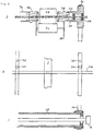
- Supports 7 are arranged for support rollers.
- the support rollers 8 are intended to hold down the cables 9.
- Several rollers 8 may be arranged.
- the cables 9 are intended to support particularly wide loads. They are driven by the load alone and run over guide pulleys 10.
- Figure 5 shows three supports 7, but either two or more than three supports are also feasible.
- a frame 11 for guide wheels 5-6 is arranged at the far end of the conveyor, and this frame 11 is also provided with guide pulleys 12-13 for the cables 9. These are on the same shaft as the rollers 5-6.
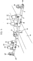
- Figure 6 shows the support 7 in more detail.
- the stand is clamped on a beam 14 by means of a wing nut 15. It can thus be displaced along the beam 14.
- a jaw 16, thicker at its lower end is used for clamping the stand.
- a holder 17 for support rollers can be moved laterally along the support 7 by means of a screw 18 or spring clamps.
- the holder 17 carries two vertical support rollers 19-20 and one horizontal support roller 21 for the belt 1.
- the vertical rollers 19-20 are spring-loaded.
- a similar holder 22 on the other side of the beam has support rollers 23-24 and 25, respectively.
- Pulleys 26-27 for support cables are provided at the ends of the support 7, and stops 28-29 outermost.
- Figure 7 shows a detail of the support rollers on the holder 17. Thanks to the spring 31, the vertical rollers 19-20 can be tilted to allow the load 30 to pass.
- a lower support wheel 32 is also arranged on the support 7, at the point when the belt crosses.
- the belt runs below the support roller 32, as shown in Figure 8. This arrangement enables the belt to be run in both directions to achieve separation.
- the support roller 32 is sufficiently wide for the two sections of belt to run adjacently. The feeders will separate when the belt has passed the support roller 32.
- the support roller 32 may be provided with edge flanges to prevent the belt 1 from slipping off.
- the invention eliminates the need for electrical or mechanical systems for synchronization and thus also access to a source of electric power, thus offering free choice. This is of course important in the building branch. The risk of accidents caused by malfunction of the synchronization system is also eliminated.
- the drive rollers need not to have exactly the same diameter. Minor differences in diameter will automatically be adjusted after a while, due to wear. Neither are two identical belts necessary.
Landscapes
- Engineering & Computer Science (AREA)
- Mechanical Engineering (AREA)
- Structure Of Belt Conveyors (AREA)
- Belt Conveyors (AREA)
Claims (9)
Priority Applications (1)
| Application Number | Priority Date | Filing Date | Title |
|---|---|---|---|
| AT86901553T ATE52479T1 (de) | 1985-02-14 | 1986-02-13 | Anordnung bei foerderbaendern. |
Applications Claiming Priority (2)
| Application Number | Priority Date | Filing Date | Title |
|---|---|---|---|
| SE8500683A SE447983B (sv) | 1985-02-14 | 1985-02-14 | Synkronisering av band hos bandtransportorer |
| SE8500683 | 1985-02-14 |
Publications (2)
| Publication Number | Publication Date |
|---|---|
| EP0249596A1 EP0249596A1 (de) | 1987-12-23 |
| EP0249596B1 true EP0249596B1 (de) | 1990-05-09 |
Family
ID=20359112
Family Applications (1)
| Application Number | Title | Priority Date | Filing Date |
|---|---|---|---|
| EP86901553A Expired EP0249596B1 (de) | 1985-02-14 | 1986-02-13 | Anordnung bei förderbändern |
Country Status (9)
| Country | Link |
|---|---|
| US (2) | US4738353A (de) |
| EP (1) | EP0249596B1 (de) |
| JP (1) | JPS62501768A (de) |
| AU (1) | AU587016B2 (de) |
| DE (1) | DE3670997D1 (de) |
| DK (1) | DK158637C (de) |
| FI (1) | FI85361C (de) |
| SE (1) | SE447983B (de) |
| WO (1) | WO1986004882A1 (de) |
Families Citing this family (7)
| Publication number | Priority date | Publication date | Assignee | Title |
|---|---|---|---|---|
| SE447983B (sv) * | 1985-02-14 | 1987-01-12 | Rolf I Johansson | Synkronisering av band hos bandtransportorer |
| US5791451A (en) * | 1996-08-19 | 1998-08-11 | E.F. Bavis & Associates, Inc. | Tape drive conveyor system with twisted conformation |
| US6053305A (en) * | 1998-04-14 | 2000-04-25 | Helmerson; Lars | Lift conveyor with single belt having criss-cross return segments |
| ITBO20010772A1 (it) * | 2001-12-21 | 2003-06-21 | M C Srl | Dispositivo di trasporto a cinghia a formato registrabile |
| US6966431B2 (en) * | 2002-02-26 | 2005-11-22 | Jervis B. Webb Company | Conveyor system for article treatment |
| US20060237285A1 (en) * | 2005-04-21 | 2006-10-26 | Desanto Anthony J | Diverter for a conveyor |
| CN115475851B (zh) * | 2022-09-14 | 2025-03-14 | 四川嘉拓智能设备有限公司 | 一种单根线材穿带设备 |
Family Cites Families (13)
| Publication number | Priority date | Publication date | Assignee | Title |
|---|---|---|---|---|
| US2573486A (en) * | 1950-02-21 | 1951-10-30 | Iowa Mfg Company | Sectional conveyer |
| US2705854A (en) * | 1951-06-30 | 1955-04-12 | Glaceries Sambre Sa | Method and apparatus for ensuring rectilinear movement of ribbons of glass subjected to continuous grinding and/or polishing |
| US2698079A (en) * | 1953-03-10 | 1954-12-28 | Joy Mfg Co | Conveyer frame structure |
| GB888059A (en) * | 1957-06-19 | 1962-01-24 | Coal Industry Patents Ltd | Improvements in and relating to conveyors |
| US2965217A (en) * | 1958-01-31 | 1960-12-20 | Gewerk Eisenhuette Westfalia | Drive for double-chain scraper conveyor |
| US3225902A (en) * | 1963-01-17 | 1965-12-28 | Ashworth Bros Inc | Belt control |
| GB1268376A (en) * | 1968-06-06 | 1972-03-29 | Stone Platt Crawley Ltd Former | Improvements relating to conveyors |
| GB1504856A (en) * | 1974-06-05 | 1978-03-22 | Ahb Services Ltd | Conveyors |
| JPS5912565B2 (ja) * | 1976-12-20 | 1984-03-24 | 松下電器産業株式会社 | 薄板の供給・取出し装置 |
| SE422566B (sv) * | 1979-04-20 | 1982-03-15 | Rolf I Johansson | Bandtransportor for exempelvis takpannor innefattande en synkroniseringsanordning |
| AU5987780A (en) * | 1979-04-20 | 1980-11-05 | Johansson, R. | Belt conveyor |
| SE436861B (sv) * | 1984-03-08 | 1985-01-28 | Rune Andersson | Anordning for astadkommande av synkroniserad gang hos minst tva transportband |
| SE447983B (sv) * | 1985-02-14 | 1987-01-12 | Rolf I Johansson | Synkronisering av band hos bandtransportorer |
-
1985
- 1985-02-14 SE SE8500683A patent/SE447983B/sv not_active IP Right Cessation
-
1986
- 1986-02-13 EP EP86901553A patent/EP0249596B1/de not_active Expired
- 1986-02-13 DE DE8686901553T patent/DE3670997D1/de not_active Expired - Lifetime
- 1986-02-13 US US06/923,145 patent/US4738353A/en not_active Expired - Fee Related
- 1986-02-13 JP JP61501385A patent/JPS62501768A/ja active Pending
- 1986-02-13 AU AU54554/86A patent/AU587016B2/en not_active Ceased
- 1986-02-13 WO PCT/SE1986/000058 patent/WO1986004882A1/en not_active Ceased
- 1986-10-10 DK DK486086A patent/DK158637C/da not_active IP Right Cessation
-
1987
- 1987-08-14 FI FI873528A patent/FI85361C/fi not_active IP Right Cessation
-
1988
- 1988-04-18 US US07/182,498 patent/US4854447A/en not_active Expired - Fee Related
Also Published As
| Publication number | Publication date |
|---|---|
| DK486086A (da) | 1986-10-10 |
| EP0249596A1 (de) | 1987-12-23 |
| FI85361C (fi) | 1992-04-10 |
| SE8500683L (sv) | 1986-08-15 |
| DK158637B (da) | 1990-06-25 |
| SE447983B (sv) | 1987-01-12 |
| WO1986004882A1 (en) | 1986-08-28 |
| DK486086D0 (da) | 1986-10-10 |
| AU587016B2 (en) | 1989-08-03 |
| AU5455486A (en) | 1986-09-10 |
| FI873528L (fi) | 1987-08-14 |
| DK158637C (da) | 1990-11-26 |
| SE8500683D0 (sv) | 1985-02-14 |
| DE3670997D1 (de) | 1990-06-13 |
| FI873528A0 (fi) | 1987-08-14 |
| JPS62501768A (ja) | 1987-07-16 |
| US4854447A (en) | 1989-08-08 |
| FI85361B (fi) | 1991-12-31 |
| US4738353A (en) | 1988-04-19 |
Similar Documents
| Publication | Publication Date | Title |
|---|---|---|
| US11548740B2 (en) | Transfer device | |
| BRPI0712288A2 (pt) | dispositivo para o tratamento de estruturas tubulares flexìveis com pelo menos um orifìcio | |
| US2374174A (en) | Apparatus for piling metallic sheets | |
| CN112978335A (zh) | 一种管件平移上料机构的工作方法 | |
| US4738353A (en) | Belt conveyor system | |
| GB2198939A (en) | Apparatus for automatically securing borderwires on mattress innersprings | |
| US4256221A (en) | Workpiece assembly machinery | |
| CN112478718B (zh) | 一种转运装置 | |
| CN212628628U (zh) | 一种机器内置式翻板机构 | |
| US4844237A (en) | Adjustable storage cassette system for printed products | |
| CZ152696A3 (en) | Clamp feeder of metal bands | |
| US4366900A (en) | Multiple belt conveyar with synchronizer | |
| CN210635514U (zh) | 线缆配送装置 | |
| US4856643A (en) | Device for retaining two parallel tracks | |
| EP0487017A1 (de) | Verfahren und Vorrichtung zur Behandlung von Treibriemen auf eine automatische Weise | |
| CN206705279U (zh) | 一种瓶装饮料的自动密封码垛系统 | |
| CN224046203U (zh) | 一种磁粉探伤用工件转运装置 | |
| US3559858A (en) | Apparatus for separating adjacent adherent rolls | |
| CN113022596B (zh) | 一种高空溜索系统 | |
| KR20220009983A (ko) | 유연한 피치를 가진 제품 계량 시스템 | |
| CN219728256U (zh) | 一种转辙机运输装置 | |
| US3650217A (en) | Sheet handling apparatus | |
| CN119820206B (zh) | 一种飞行器承力杆加工用双端同步焊接装置 | |
| CN113321042B (zh) | 一种服装加工的布料分隔铺线装置 | |
| CN222860493U (zh) | 卷料输送装置及夹持上料平台 |
Legal Events
| Date | Code | Title | Description |
|---|---|---|---|
| PUAI | Public reference made under article 153(3) epc to a published international application that has entered the european phase |
Free format text: ORIGINAL CODE: 0009012 |
|
| 17P | Request for examination filed |
Effective date: 19871001 |
|
| AK | Designated contracting states |
Kind code of ref document: A1 Designated state(s): AT BE CH DE FR GB IT LI LU NL SE |
|
| 17Q | First examination report despatched |
Effective date: 19880715 |
|
| GRAA | (expected) grant |
Free format text: ORIGINAL CODE: 0009210 |
|
| AK | Designated contracting states |
Kind code of ref document: B1 Designated state(s): AT BE CH DE FR GB IT LI LU NL SE |
|
| PG25 | Lapsed in a contracting state [announced via postgrant information from national office to epo] |
Ref country code: SE Effective date: 19900509 |
|
| REF | Corresponds to: |
Ref document number: 52479 Country of ref document: AT Date of ref document: 19900515 Kind code of ref document: T |
|
| ITF | It: translation for a ep patent filed | ||
| REF | Corresponds to: |
Ref document number: 3670997 Country of ref document: DE Date of ref document: 19900613 |
|
| ET | Fr: translation filed | ||
| PLBE | No opposition filed within time limit |
Free format text: ORIGINAL CODE: 0009261 |
|
| STAA | Information on the status of an ep patent application or granted ep patent |
Free format text: STATUS: NO OPPOSITION FILED WITHIN TIME LIMIT |
|
| 26N | No opposition filed | ||
| PGFP | Annual fee paid to national office [announced via postgrant information from national office to epo] |
Ref country code: LU Payment date: 19920220 Year of fee payment: 7 |
|
| EPTA | Lu: last paid annual fee | ||
| PG25 | Lapsed in a contracting state [announced via postgrant information from national office to epo] |
Ref country code: LU Free format text: LAPSE BECAUSE OF NON-PAYMENT OF DUE FEES Effective date: 19930213 |
|
| ITTA | It: last paid annual fee | ||
| PGFP | Annual fee paid to national office [announced via postgrant information from national office to epo] |
Ref country code: NL Payment date: 19930228 Year of fee payment: 8 |
|
| PGFP | Annual fee paid to national office [announced via postgrant information from national office to epo] |
Ref country code: GB Payment date: 19930812 Year of fee payment: 8 |
|
| PGFP | Annual fee paid to national office [announced via postgrant information from national office to epo] |
Ref country code: FR Payment date: 19930827 Year of fee payment: 8 Ref country code: CH Payment date: 19930827 Year of fee payment: 8 |
|
| PGFP | Annual fee paid to national office [announced via postgrant information from national office to epo] |
Ref country code: AT Payment date: 19930830 Year of fee payment: 8 |
|
| PGFP | Annual fee paid to national office [announced via postgrant information from national office to epo] |
Ref country code: BE Payment date: 19930913 Year of fee payment: 8 |
|
| PGFP | Annual fee paid to national office [announced via postgrant information from national office to epo] |
Ref country code: DE Payment date: 19931012 Year of fee payment: 8 |
|
| PG25 | Lapsed in a contracting state [announced via postgrant information from national office to epo] |
Ref country code: GB Effective date: 19940213 Ref country code: AT Effective date: 19940213 |
|
| PG25 | Lapsed in a contracting state [announced via postgrant information from national office to epo] |
Ref country code: LI Effective date: 19940228 Ref country code: CH Effective date: 19940228 Ref country code: BE Effective date: 19940228 |
|
| BERE | Be: lapsed |
Owner name: JOHANSSON ROLF Effective date: 19940228 |
|
| PG25 | Lapsed in a contracting state [announced via postgrant information from national office to epo] |
Ref country code: NL Effective date: 19940901 |
|
| GBPC | Gb: european patent ceased through non-payment of renewal fee |
Effective date: 19940213 |
|
| NLV4 | Nl: lapsed or anulled due to non-payment of the annual fee | ||
| PG25 | Lapsed in a contracting state [announced via postgrant information from national office to epo] |
Ref country code: FR Effective date: 19941031 |
|
| REG | Reference to a national code |
Ref country code: CH Ref legal event code: PL |
|
| PG25 | Lapsed in a contracting state [announced via postgrant information from national office to epo] |
Ref country code: DE Effective date: 19941101 |
|
| REG | Reference to a national code |
Ref country code: FR Ref legal event code: ST |
|
| PG25 | Lapsed in a contracting state [announced via postgrant information from national office to epo] |
Ref country code: IT Free format text: LAPSE BECAUSE OF NON-PAYMENT OF DUE FEES Effective date: 20050213 |