EP0249634B1 - Prägemechanismus mit direktem antrieb durch elektromagneten - Google Patents
Prägemechanismus mit direktem antrieb durch elektromagneten Download PDFInfo
- Publication number
- EP0249634B1 EP0249634B1 EP87900559A EP87900559A EP0249634B1 EP 0249634 B1 EP0249634 B1 EP 0249634B1 EP 87900559 A EP87900559 A EP 87900559A EP 87900559 A EP87900559 A EP 87900559A EP 0249634 B1 EP0249634 B1 EP 0249634B1
- Authority
- EP
- European Patent Office
- Prior art keywords
- solenoid
- shaft
- embossing
- imprinting
- force
- Prior art date
- Legal status (The legal status is an assumption and is not a legal conclusion. Google has not performed a legal analysis and makes no representation as to the accuracy of the status listed.)
- Expired
Links
Images



Classifications
-
- B—PERFORMING OPERATIONS; TRANSPORTING
- B41—PRINTING; LINING MACHINES; TYPEWRITERS; STAMPS
- B41J—TYPEWRITERS; SELECTIVE PRINTING MECHANISMS, i.e. MECHANISMS PRINTING OTHERWISE THAN FROM A FORME; CORRECTION OF TYPOGRAPHICAL ERRORS
- B41J3/00—Typewriters or selective printing or marking mechanisms characterised by the purpose for which they are constructed
- B41J3/38—Typewriters or selective printing or marking mechanisms characterised by the purpose for which they are constructed for embossing, e.g. for making matrices for stereotypes
Definitions
- the present invention relates to an apparatus for imprinting sheet material with characters according to the preamble of claim 1.
- a solenoid driven embossing mechanism of this type can be used for embossing information onto a common credit card.
- the printing elements are connected via a linkage to a plunger which is cam shaft driven to move the printing elements into contact with the sheet material, whereupon the imprinting force is applied to the plunger by a solenoid.
- the object is solved by the features of claim 1.
- the subclaims characterize further particularly useful features. Accordingly the cooperating punches and dies are inserted in slots positioned about the circumference of punch and die wheels rotatable in synchronism with each other to permit positioning of a selected punch and die pair on both sides of sheet material positioned in an emboss location and improved embossing pressure applying mechanism.
- FIG. 2 is a sectional view taken along the line 2-2 of FIG. 1.
- FIG. 3 is a sectional view taken along line 3-3 of FIG. 1.
- FIG. 4 is a schematic electrical diagram of the solenoid drive circuitry.
- FIG. 5 is a sectional view taken along the line 5-5 of FIG. 1.
- FIG. 6 is a fragmentary sectional view of an alternate embodiment of an embossing mechanism utilizing only a single solenoid and is the view that would be seen viewing along the line 6-6 of FIG. 5.
- FIG. 7 is a sectional view of another embodiment of the embossing mechanism with the section taken in the same manner as FIG. 1.
- FIG. 8 is a sectional view of yet another embodiment of the embossing mechanism with the section taken in the same manner as FIGS. 1 and 7.
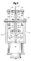
- FIG. 9 is a sectional view of a further embodiment of the embossing mechanism with the section taken vertically through the rotational axis of the printwheel.
- FIG. 10 is a sectional view of a still further embodiment of the embossing mechanism with the section taken in the same manner as in FIG. 9.
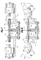
- FIG. 1 shows the important elements of one of the preferred embodiments of the direct solenoid drive embossing mechanism 10.
- the punch and die embossing elements of the basic embossing system are similar to what is shown in U. S. Pat. No. 4,271,012 and U. S. Pat. No. 4,519,600, both of which are assigned to the assignee of the present invention.
- a pair of type element wheels 12 and 14 are mounted on a common shaft 16 and secured by set screws 18 located in hubs 20.
- set screws 18 located in hubs 20.
- use of a single shaft 16 is not necessary since other means can be utilized to synchronize the rotation of wheels 12 and 14, even if they are mounted on separate but coaxial shafts.
- Shaft 16 is supported on frame 22 by bearings 24. Shaft 16 is driven by positioning mechanisms as shown in U. S. Pat. No. 4,271,012 so that appropriate pairs of punch elements, such as 26, on wheel 14 and die elements, such as 28, on wheel 12 are positioned for embossing.
- FIG. 2 shows the embossing punch 26 aligned with an aperture 25 in a stationary guide plate 27. Guide plates 27 define an embossing area 30 between them.
- linear solenoids 40 are each secured to frame 22 with their shafts 42 projecting and aligned with the axis of linear movement of punch and die members 28 and 26 into and away from embossing area 30.
- Suitable linear solenoids 40 are manufactured by Ledex Inc., 801 Scholz Drive, Vandalia, Ohio 45377, and described as axial solenoids Part Nos. 189987 or 187790.
- shaft 42 is secured in an inner sleeve 44 which may be adhesively secured to shaft 42 using a set screw, by shrink fit or by the use of a suitable adhesive.
- shaft 42 can be threaded to threadably engage inner threads on outer sleeve 50.
- Sleeve 44 has a set of outer threads 46 which engage corresponding threads 48 on the inner wall of outer sleeve 50.
- Outer sleeve 50 is secured to inner sleeve 44 using a set screw 52 which can be tightened to apply pressure to the threads of inner sleeve 44.
- a restraining spring 62 is seated in aperture 60 of frame 22 so that one end bears upon the frame 22 while the other end bears upon a grip ring 64, which is attached to drive pin 56.
- drive pin 56 can have a projecting shoulder or head, rather than ring 64, to hold spring 62.
- Spring 62 is a compression spring which biases the linkage elements and solenoid shaft 42 into a rest position so that drive pin 56 is normally spaced from the head of punch and die members 26 and 28, thereby permitting wheels 12 and 14 to be rotated without interference to position selected punch and die sets for embossing.
- the restraining force of spring 62 is preferably kept at as low a level as possible to facilitate the adjusting of the solenoid current to minimize impact noise as described in more detail below.
- solenoid 40 When the selected pair of punch and die elements 26 and 28 are positioned in the embossing area, solenoid 40 is actuated to drive shaft 42 toward the embossing area, thereby moving inner sleeve 44, outer sleeve 50 and drive pin 56 toward the embossing area, striking punch or die member 26 or 28 and forcing it into engagement with card 32 in embossing area 30. If sufficient travel of shaft 42 occurs and a sufficient force is developed, the card will be embossed with the character defined by the punch and die members 26 and 28.
- An important advantage of the direct solenoid driven embossing mechanisms of this invention is that there need be no long delay between the time that the selected embossing area of the card is in position and the application of the punch and die to the card.
- each character is delayed by about one-half cam rotation for each character.
- solenoid 40 can be energized as soon as the card is in position to receive the character, and a shorter time is required to emboss a series of characters.
- solenoid 40 if actuated with a single electrical drive pulse, provides a very sharp impact between driver pin 56 and punch or die element 28, in addition to the noise as the solenoid reaches its internal stop, an extremely noisy embossing operation occurs, unless modifications are made to the solenoid drive. This is due in part to the fact that the solenoid armature and linkage have a considerable mass which is moving at a relatively high speed at the time that it overcomes the compression force of spring 62 and impacts the surface of card 32.
- the solenoid 40 should be energized in two stages. In the first stage of energization, sufficient voltage is applied to the solenoid for sufficient time merely to allow drive pin 56 to engage punch or die member 26 or 28 and bring it into contact with the surface of card 32. After punch 26 and die 28 have been brought into contact with card 32, solenoid 40 is energized again for a longer time interval to apply force to the punch and die member to emboss the card. Because punch and die 26 and 29 are already in contact with card 32 when the embossing force is applied, the loud impact noise of the printing elements striking the card is avoided and the pressure applying step necessary for completion of the embossing operation occurs with little noise.
- the impact of the movable solenoid shaft 42 against the internal stop is also reduced because the control of the energization pulse reduces the velocity of the moving parts without reducing the embossing force.
- Using an extremely short interval for the first voltage application to solenoid 40 results in a much lower impact force between the face of the type element and card 32 and therefore reduces the total noise of the operation without degrading the quality of the embossing. It also may allow for longer life of the mechanical embossing elements.
- embossing command voltage in two parts to accomplish quiet embossing can be performed by the control circuitry of the embossing machine. After the proper punch and die pair are in the emboss area 30 and card 32 is correctly positioned, the emboss command voltage may be applied to solenoid 40. It has been found that optimum operation for typical plastic card stock occurs when the initial voltage application lasts for approximately 4 msecs. followed by a period when no voltage is applied for approximately 5 msecs. and then the voltage is applied for a further 75 to 100 msecs. to complete the embossing operation. Approximately 200 msec. is required to return the elements to their rest position at the completion of the embossing operation.
- FIG. 4 A suitable circuit for driving solenoid 40 in response to a two part command signal is shown in FIG. 4.
- a full-wave rectifier comprised of diodes D1 through D4 rectifies the AC voltage applied to input terminals 80.
- the full wave rectified DC voltage is filtered by resistor R1 and capacitors C1 and C2.
- the voltage is then further filtered by resistor R2 and capacitor C3 and limited to zener diode D6 and applied to the collector of a photocoupled transistor 82 which in turn controls the flow of current to resistor R3 which develops the voltage for controlling field effect transistor Q1 which provides the power switching action for the winding of solenoid 40.
- a flyback diode D5 suppresses the inductive voltage transient when switch Q1 is turned off with a strong current flowing in solenoid winding 40.
- the circuit in FIG. 4 operates by turning the NPN transistor of photocoupled transistor 82 ON when light is received from photodiode 84 in the photoconductor package in response to actuation of LED 84 by the presence of a command voltage on terminals 86.
- the input to input terminals 86 which can be provided by an output port of the computer used to control the operations of embossing mechanism 10 or by any other suitable analog or digital circuitry which can provide the desired short initial pulse to allow the type elements to move into contact with the card surface with minimum impact force and then to apply the full embossing force after the type elements are in contact with the surface of the card, thereby minimizing the noise created by a full force impact of the type elements into the surface of a card.
- the matching of the command signal for the solenoid can also be used to vary the embossing force and to form smaller characters in a short interval, while larger characters receive more force and a longer cycle time.
- nearly 50 msec. is required to allow the magnetic field to fully build up. Since the embossing force is directly proportional to the field strength, the full 50 msec. is required to emboss characters like a capital "8" which requires about 1100N [250 pounds] of embossing force.
- a simple ".” requires between 200N [50 pounds] and 400N [100 pounds] of embossing force. That force can be built up in about 20 msec.
- the embossing forces can be matched to the character being embossed by varying the time duration of the excitation to solenoid 40 or by monitoring the current wave shape to solenoid to determine when plunger 42 has stopped moving.
- the command applied to terminals 86 can have a different length for each character in accordance with stored information in the electronic circuitry (not shown) used to select the characters and to otherwise control the operation of the machine.
- the type elements may each be provided with return springs as shown in FIG. 8C of U. S. Pat. No. 4,271,012, to assist them in returning to their rest position as shown in FIG. 1, separated from the surface of card 32.
- return springs 29 can be mounted in each type element to provide a spring for returning the type element to the rest position.
- a retractor plate 90 is attached to a retractor arm 92 using an attachment screw 94.
- Retractor arm 92 is in turn secured to outer sleeve 50 using a screw 96 and washer 98.
- Retractor arm 92 hooks the flange 31 of the punch 26 or die 28 and positively retracts that element from the embossing position as solenoid 40 is deenergized.
- the engagement of the retractor and die element 28 is shown in FIG. 5.
- An oversized slot 99 in retractor arm 92 permits adjusting the extension of retractor plate 90.
- Use of retractor plate 90 may obviate the need for the individual return springs 29.
- a reverse current could also be applied to solenoid 40 to allow for a quicker return of plunger 42 thereby yielding faster cycle time.
- FIG. 7 shown another embodiment of the embossing mechanism utilizing a modified coupling arrangement for linear solenoids aligned with the axis of movement of the punch and die elements 26 and 28, respectively.
- linear solenoids 40 are long stroke linear solenoids which move shaft 42 a significantly greater distance upon actuation than solenoids 40 shown in FIGS. 1 through 6.
- solenoid plungers 42 are accelerated along the axis of movement of punch and die print elements 26 and 28 when solenoids 40 are actuated. Plungers 42 then strike drive pins 56 which, in turn, are driven against the print elements 26 and 28 to move them into embossing or imprinting contact with card 32.
- FIGS. 7 shown another embodiment of the embossing mechanism utilizing a modified coupling arrangement for linear solenoids aligned with the axis of movement of the punch and die elements 26 and 28, respectively.
- linear solenoids 40 are long stroke linear solenoids which move shaft 42 a significantly greater distance upon actuation than solenoids 40 shown in FIG
- the embosser shown in FIG. 7 applies the embossing force during a relatively short time interval with a large embossing force.
- the embossing energy is provided by the kinetic energy of plungers 42 and drive pins 56 as they move against punch and die members 26 and 28. Plungers 42 are accelerated to a relatively high velocity by solenoids 40. Since the amount of energy imparted to print elements 26 and 28 is dependent upon the square of the velocity of the impacting parts, the print elements 26 and 28 are capable of providing a significant embossing force which may be suitable for embossing metal, cards which require more embossing force such as cards 32, for example. Plastic cards can, of course, also be embossed.
- a restoring force is provided by spring 62 which bears upon frame 22 at one end and a retaining clip 102 mounted at the end of drive pin 56 which was struck by plunger 42 to effect the embossing operation.
- spring 62 which bears upon frame 22 at one end and a retaining clip 102 mounted at the end of drive pin 56 which was struck by plunger 42 to effect the embossing operation.
- FIG. 7 provides a relatively simple linkage since the solenoids used to generate the embossing force provide their linear output force along the axis of movement of embossing elements 26 and 28.
- FIG. 8 shows another form of embossing mechanism utilizing rotary solenoids 104, rather than linear solenoids 40, to generate the embossing forces.
- Solenoid 104 has an output shaft 106 which is rotated upon actuation of the solenoid.
- Shaft 106 drives a link 108 which is pivotally connected to a further link 110 which is, in turn, pivotally connected to drive pin 56 which is supported in an oil-lite bearing 58 which defines an aperture through frame 22 for supporting shaft 56 for linear oscillatory motion along the printing axis of punch and die print elements 26 and 28.
- rotation of shaft 106 of rotary solenoids 104 moves the linkage formed of links 108 and 110 from the solid line positions shown in FIG.
- the embossing operation can be accomplished with a solenoid which is selectively energized between embossing steps and uses spring force to effect the embossing when the energization is removed.
- the mechanism can alternatively be provided by a double-acting solenoid which, when actuated in the reverse direction, drives from the position shown in dashed outline to the initial position to effectuate a second embossing operation.
- FIG. 9 a further embodiment of the solenoid driven embossing mechanism is shown.
- the punch and die elements 26 and 28 are mounted in the same manner relative to card 32.
- a single linear solenoid 40 drives a shaft 42 which is connected to a pair of links 120 and 122 which are in turn pivotally connected at one end to links 120 and 122 and have adjusting screws 130 and 132 inserted in suitable threaded openings at their other ends.
- Links 124 and 126 are pivotally supported at a location between the ends by suitable clevis and bearing arrangements 134 and 136, respectively.
- solenoid 40 can either be a double-acting solenoid to apply an embossing force each time shaft 42 moves between the two positions illustrated or, alternatively, solenoid 40 can be single-acting with a biased restoring spring to return shaft 42 to the initial position after an embossing cycle when the printwheels 12 and 14 are positioned so that no punch and die members 26 and 28 are engaged by adjusting screws 130 and 132 during the portion of the cycle when the solenoid returns to its initial position.
- FIG. 10 also illustrates an embossing mechanism where a single solenoid is used to provide the embossing force for both the punch and die members.
- the embodiment shown in FIG. 10 utilizes a rotary solenoid 104 which drives a shaft 106 which is, in turn, connected to a link 108 which is pivotally connected to one end of a connecting link 110, the other end of which is pivotally connected to a sliding shaft 112 which is restrained for movement along an axis perpendicular to that of shaft 106.
- Further links 140 and 142 are pivotally connected to sliding shaft 112 which is restrained from movement other than along the axis of track 114.
- the solenoid 10 can be operated either in a double-acting mode utilizing separate coils to drive the rotary solenoid to and from each of the two operating positions or, alternatively, the solenoid can be single-acting with a return spring returning the mechanism to an initial position after a character is embossed and the printwheel is rotated to move print elements 26 and 28 out of line with the adjusting screws 130 and 132 at the ends of links 124 and 126.
- FIG. 11 is an additional embodiment of the embossing mechanism utilizing a pair of rotary solenoids 104 which couple their rotary action to drive forces applied to type elements 26 and 28 utilizing links 124 and 126.
- Each of the rotary solenoids 104 drives shaft 106 which is rigidly connected to one end of link 108, the other end of which is pivotally connected to one end of link 110, the other end of which is pivotally connected to the end of link 124 or 126 which is opposite to the end to which adjusting screw 130 or 132 is attached.
- solenoid 104 can either be single or double acting.
- FIG. 12 shows a simplified rotary solenoid linkage where rotary solenoids 104 drive shafts 106 which are directly connected to one end of link 108, the other end of which carries adjusting screws 130 and 132. Solenoids 104 are actuated to rotate shaft 106 and link 108 to apply direct embossing force to punch and die elements 26 and 28 to adjusting screws 130 and 132. These solenoids can either be double-acting to return them to the initial position or can be biased to return to their initial position using spring force after the actuating energy is removed.
Landscapes
- Credit Cards Or The Like (AREA)
- Printers Characterized By Their Purpose (AREA)
- Sheets, Magazines, And Separation Thereof (AREA)
- Printers Or Recording Devices Using Electromagnetic And Radiation Means (AREA)
Claims (16)
- Vorrichtung zum Prägen von Zeichen in Blech mit mehreren zusammenwirkenden Prägeelementen (26, 28), die in Schlitze am Umfang von zusammenwirkenden Prägerädern (12, 14) eingesetzt sind, die abgestimmt aufeinander an einem Rahmen (22) drehbar sind, um ein Element von zwei Prägeelementen (26, 28) auf jeder Seite des Bleches (32) in einem Prägebereich zu positionieren; und mit einem Mechanismus zum Aufbringen einer Prägekraft, der aufweista) einen Magnet (40) am Rahmen (22) mit einem Schaft (42), der bei Erregung des Magneten aus einer ersten in eine zweite Lage bewegbar ist,b) einer an dem Schaft des Magneten befestigten Verbindung (44, 50, 56) zum Übertragen der Bewegung längs der Prägeachse auf eines der beiden Prägeelemente (26, 28) undc) einen Magnetantrieb zum Zuführen von Energie an den Magnet (40) zur Bewegung des Schafts zwischen der ersten und zweiten Position und zum Prägen des im Prägebereich angeordneten Bereiches mit einem ausgewählten Zeichen, dadurch gekennzeichnet, daß der Magnetantrieb Mittel zum Erregen des Magneten in zwei Stufen aufweist, wobei die erste Stufe den Magneten erregt, um die Verbindung (44, 50, 56) in Berührung mit dem Prägeelement zu bringen und das Prägeelement (26, 28) in Berührung mit dem Blech (32) zu bewegen, und die zweite Stufe den Magneten erregt, um Prägekraft auf das Prägeelement auszuüben, um den Lärm des Prägevorgangs zu verringern, wobei die von dem Magneten auf das Prägeelement in der zweiten Stufe ausgeübte Kraft größer ist als die vom Magneten auf das Prägeelement in der ersten Stufe ausgeübte Kraft.
- Vorrichtung nach Anspruch 1, wobei der Magnet (40) mindestens eine Wicklung und eine dämpfende Feder (62) aufweist und der Magnetantrieb Mittel zum Aktivieren der Wicklung aufweist, um den Schaft in einer Richtung von jeweils einer der beiden Positionen in die andere der beiden Positionen zu bewegen und die dämpfende Feder zum Zurückholen des Schafts in die Ursprungsposition der beiden Positionen vorgesehen ist.
- Vorrichtung nach Anspruch 1 oder 2, wobei der Magnetantrieb an den Magneten (40) eine Spannung für eine Zeitdauer anlegt, die so ausgewählt ist, daß eine für die Größe und Komplexität des prägenden Zeichens entsprechende Prägekraft erzeugt wird.
- Vorrichtung nach einem der Ansprüche 1 bis 3, wobei die Verbindung (44, 50, 56) mechanische Mittel (90) zum Erfassen des Typenelements (26, 28) aufweist, um dieses nach Beendigung des Prägevorgangs in das Prägerad zurückzuholen, wenn der Magnet (40) in die erste Position zurückkehrt und das Ausüben von Prägekraft beendet.
- Vorrichtung nach einem der Ansprüche 1 bis 4, wobei beide Prägeelemente von dem Magnet angetrieben sind.
- Vorrichtung nach einem der Ansprüche 1 bis 4, wobei eines der zusammenwirkenden Prägeelemente (26, 28) von dem Magnet (40) angetrieben ist und das andere von einer Nockenvorrichtung (100) bewegbar ist, die im Prägebereich angeordnet ist und nur jene in der Nachbarschaft des Prägebereichs liegenden Prägelemente aus dem Prägerad in Eingriff mit dem vom Magnet betätigten Prägelement bewegt.
- Vorrichtung nach einem der Ansprüche 1 bis 6, wobei die Verbindung einen mit der Prägeachse fluchtenden, verschiebbar angeordneten Antriebsstift (56) aufweist, der mit einem Ende neben dem Prägeelement angeordnet ist, wobei die Verbindung zur Kupplung des Magnetschafts mit dem Prägeelement ausgebildet ist.
- Vorrichtung nach Anspruch 7, wobei die Verbindung derart ausgebildet ist, daß der Schaft (42) des Magneten (40) anfänglich unabhängig von dem Antriebsstift (56) bewegbar ist und an den Antriebsstift anschlägt, um kinetische Energie von dem Magnetschaft auf den Antriebsstift zu übertragen.
- Vorrichtung nach Anspruch 1, wobei der Magnet (40) ein unterhalb der Prägeräder (12, 14) angeordneter linearer Magnet ist, dessen Schaft zwischen der ersten und zweiten Position in einer Achse bewegbar ist, die rechtwinklig die Drehachsen der Prägeräder schneidet, und wobei die Verbindung einen am Rahmen schwenkbar gelagerten Hebel (124, 126) aufweist, dessen erstes Ende eines der Prägeelemente erfaßt, und dessen anderes Ende mit dem Magnetschaft über ein Gelenk (120, 122) gekuppelt ist, das so ausgebildet ist, daß das erste Ende des Hebels auf das Prägeelement eine Prägekraft ausübt, wenn sich der Schaft zwischen der ersten und zweiten Position bewegt.
- Vorrichtung nach Anspruch 9, wobei die Verbindung Hebel (124, 126) zum Kuppeln der Bewegung des Magnetschaftes zu den Prägeelementen beider Prägeräder aufweist.
- Vorrichtung nach Anspruch 1, wobei der Magnet ein unterhalb der Prägeräder angeordneter rotierender Magnet (104) ist, ein Kurbelarm (108) mit einem Ende mit der Welle (106) des Magneten und an dem anderen Ende mit einem Schiebeglied (112) gekuppelt ist, das an einer Bewegung in einer rechtwinklig zur Magnetwelle liegenden Achse gehindert ist, und wobei die Verbindung einen schwenkbar am Rahmen angeordneten Hebel (124, 126) aufweist, dessen erstes Ende eines der Prägeelemente erfaßt und dessen anderes Ende mit dem Schiebeglied über ein Gelenk (140, 142) gekuppelt ist, das so ausgebildet ist, daß das erste Ende des Hebels eine Prägekraft auf das Prägeelement ausübt, wenn die Welle des drehbaren Magneten von einer ersten in eine zweite Drehlage gelangt.
- Vorrichtung nach Anspruch 1, wobei der Magnet mindestens einen drehbaren, unterhalb der Prägeräder angeordneten Magnet (104) aufweist, die Welle (106) zwischen einer ersten und zweiten Drehlage bewegbar ist, die Verbindung einen am Rahmen schwenkbar angeordneten Hebel (124, 126) aufweist, dessen erstes Ende eines der Prägeelemente erfaßt und dessen anderes Ende mit der Welle des drehbaren Magneten über ein Gelenk (108, 110) gekuppelt ist, das so ausgebildet ist, daß das erste Ende des Hebels eine Prägekraft auf das Prägeelement ausübt, wenn die Welle sich zwischen der ersten und zweiten Drehlage bewegt.
- Vorrichtung nach Anspruch 1, wobei der Magnet mindestens einen am Rahmen neben den Prägerädern angeordneten drehbaren Magnet aufweist, die Verbindung einen Kurbelarm aufweist, der mit einem Ende an der Welle derart gekuppelt ist, daß das andere Ende das Prägeelement erfaßt, um eine Prägekraft auf dieses auszuüben, wenn sich der drehbare Magnet aus einer ersten Drehlage in eine zweite Drehlage bewegt.
- Vorrichtung nach einem der Ansprüche 1 bis 13, wobei die Welle bzw. der Schaft des Magneten zwischen der ersten und zweiten Stufe im wesentlichen zu einem Halt gelangt.
- Vorrichtung nach einem der Ansprüche 1 bis 14, wobei die erste und zweite Stufe von einem vorbestimmten Zeitintervall voneinander getrennt sind.
- Vorrichtung nach einem der Ansprüche 1 bis 15, wobei die in der zweiten Stufe ausgeübte Prägekraft abhängig von dem zu druckenden Zeichen wahlweise veränderlich ist.
Priority Applications (1)
| Application Number | Priority Date | Filing Date | Title |
|---|---|---|---|
| AT87900559T ATE78756T1 (de) | 1985-12-12 | 1986-12-12 | Praegemechanismus mit direktem antrieb durch elektromagneten. |
Applications Claiming Priority (2)
| Application Number | Priority Date | Filing Date | Title |
|---|---|---|---|
| US80862385A | 1985-12-12 | 1985-12-12 | |
| US808623 | 1985-12-12 |
Publications (3)
| Publication Number | Publication Date |
|---|---|
| EP0249634A1 EP0249634A1 (de) | 1987-12-23 |
| EP0249634A4 EP0249634A4 (de) | 1989-04-12 |
| EP0249634B1 true EP0249634B1 (de) | 1992-07-29 |
Family
ID=25199293
Family Applications (1)
| Application Number | Title | Priority Date | Filing Date |
|---|---|---|---|
| EP87900559A Expired EP0249634B1 (de) | 1985-12-12 | 1986-12-12 | Prägemechanismus mit direktem antrieb durch elektromagneten |
Country Status (6)
| Country | Link |
|---|---|
| EP (1) | EP0249634B1 (de) |
| JP (1) | JP2561499B2 (de) |
| AT (1) | ATE78756T1 (de) |
| CA (1) | CA1325921C (de) |
| DE (1) | DE3686262T2 (de) |
| WO (1) | WO1987003539A1 (de) |
Families Citing this family (5)
| Publication number | Priority date | Publication date | Assignee | Title |
|---|---|---|---|---|
| WO1990006237A2 (en) * | 1988-11-23 | 1990-06-14 | Datacard Corporation | Method and apparatus for driving and controlling an improved solenoid impact imprinter |
| US5070781A (en) * | 1988-11-23 | 1991-12-10 | Datacard Corporation | Card embossing apparatus and method |
| US5204802A (en) * | 1988-11-23 | 1993-04-20 | Datacard Corporation | Method and apparatus for driving and controlling an improved solenoid impact printer |
| US5266784A (en) * | 1990-02-16 | 1993-11-30 | Intermark Corporation | Promotional scanning and validating device |
| US7866904B2 (en) * | 2007-03-06 | 2011-01-11 | Datacard Corporation | Desktop card printer with indent printing apparatus and method of printing |
Family Cites Families (12)
| Publication number | Priority date | Publication date | Assignee | Title |
|---|---|---|---|---|
| US2927676A (en) * | 1956-10-24 | 1960-03-08 | Italiana Machine Aziendali Fab | Rotary keyboard punching machine |
| US3001624A (en) * | 1958-07-03 | 1961-09-26 | Adrema Werke Gmbh | Keyboard embossing machine |
| DE1463045A1 (de) * | 1964-06-24 | 1969-09-18 | Citograf Aktiebolag | Elektromechanische Steuervorrichtung und mit der Steuervorrichtung ausgeruestete tastenbetaetigte Praegemaschine |
| US3900094A (en) * | 1973-05-10 | 1975-08-19 | Lrc Inc | Matrix printer with overlapping print dots |
| US3712212A (en) * | 1971-11-12 | 1973-01-23 | Burroughs Corp | Variable printer intensity control |
| DE2211044A1 (de) * | 1972-03-08 | 1973-09-20 | Prontor Werk Gauthier Gmbh | Maschine zum praegen von schriftzeichen, insbesondere auf kunststofffolienstreifen |
| AT361514B (de) * | 1974-12-03 | 1981-03-10 | Adrema Pitney Bowes Gmbh | Adressendruckmaschine |
| US3998153A (en) * | 1975-03-18 | 1976-12-21 | Sperry Rand Corporation | High frequency power integrating printer |
| US4378733A (en) * | 1980-10-20 | 1983-04-05 | Data Card Corporation | Embossing drive mechanism for an automatic embossing system |
| US4407595A (en) * | 1981-08-31 | 1983-10-04 | Digital Equipment Corporation | Color printing apparatus |
| US4476781A (en) * | 1982-09-30 | 1984-10-16 | American Can Company | Apparatus for stamping indicia on materials |
| DE3330563A1 (de) * | 1983-08-24 | 1985-03-14 | Pitney Bowes Deutschland Gmbh, 6148 Heppenheim | Antriebsvorrichtung fuer eine praegemaschine |
-
1986
- 1986-12-12 CA CA000525199A patent/CA1325921C/en not_active Expired - Fee Related
- 1986-12-12 DE DE8787900559T patent/DE3686262T2/de not_active Expired - Fee Related
- 1986-12-12 WO PCT/US1986/002730 patent/WO1987003539A1/en not_active Ceased
- 1986-12-12 AT AT87900559T patent/ATE78756T1/de not_active IP Right Cessation
- 1986-12-12 JP JP62500572A patent/JP2561499B2/ja not_active Expired - Lifetime
- 1986-12-12 EP EP87900559A patent/EP0249634B1/de not_active Expired
Also Published As
| Publication number | Publication date |
|---|---|
| DE3686262D1 (de) | 1992-09-03 |
| DE3686262T2 (de) | 1993-03-11 |
| WO1987003539A1 (en) | 1987-06-18 |
| ATE78756T1 (de) | 1992-08-15 |
| EP0249634A1 (de) | 1987-12-23 |
| JP2561499B2 (ja) | 1996-12-11 |
| CA1325921C (en) | 1994-01-11 |
| JPS63501703A (ja) | 1988-07-14 |
| EP0249634A4 (de) | 1989-04-12 |
Similar Documents
| Publication | Publication Date | Title |
|---|---|---|
| US7913618B2 (en) | Punch press tool for stamping successive multicharacter impressions into a workpiece | |
| US4378733A (en) | Embossing drive mechanism for an automatic embossing system | |
| EP0249634B1 (de) | Prägemechanismus mit direktem antrieb durch elektromagneten | |
| US4261663A (en) | Machines for writing braille type | |
| US5320435A (en) | Direct solenoid drive imprinting mechanism | |
| US3538735A (en) | Multiple side punching machine | |
| US4220085A (en) | Low-noise printing device | |
| US3648602A (en) | Parallel input printing mechanism | |
| EP0142635A1 (de) | Antriebsvorrichtung für eine Prägemaschine | |
| DE3380252D1 (en) | Embossing machine for character dies | |
| US4203675A (en) | Pressure printer | |
| CA1089258A (en) | Advancing assembly for a high speed press | |
| JPH0645246B2 (ja) | パルス始動式プリンタ用ハンマバンク駆動装置及び方法 | |
| US3882772A (en) | Method and apparatus for impressing identifying characters into metal bar stock | |
| DE3829174C2 (de) | Typenrad-Prägevorrichtung zum Herstellen von Oberflächenprägungen auf Gegenständen, insbesondere Typenschildern | |
| EP0382500A3 (de) | Maschine mit rotierender Steuernocke, die von transportierten Blättern aktiviert wird | |
| JPS57176189A (en) | Electric-powered typewriter | |
| US3540374A (en) | Printing apparatus employing roller platen and traveling carriage | |
| JPS6210142Y2 (de) | ||
| JPH031256Y2 (de) | ||
| DE69111395T2 (de) | Anschlagdrucker. | |
| JPH0235486Y2 (de) | ||
| DE2719122A1 (de) | Einrichtung zum kennzeichnen von industriellen erzeugnissen | |
| CA2003435A1 (en) | Card embossing apparatus and method | |
| JPS5837651Y2 (ja) | 印字装置の活字位置決め構造 |
Legal Events
| Date | Code | Title | Description |
|---|---|---|---|
| PUAI | Public reference made under article 153(3) epc to a published international application that has entered the european phase |
Free format text: ORIGINAL CODE: 0009012 |
|
| AK | Designated contracting states |
Kind code of ref document: A1 Designated state(s): AT BE CH DE FR GB IT LI LU NL SE |
|
| 17P | Request for examination filed |
Effective date: 19871211 |
|
| A4 | Supplementary search report drawn up and despatched |
Effective date: 19890412 |
|
| 17Q | First examination report despatched |
Effective date: 19900907 |
|
| ITTA | It: last paid annual fee | ||
| GRAA | (expected) grant |
Free format text: ORIGINAL CODE: 0009210 |
|
| AK | Designated contracting states |
Kind code of ref document: B1 Designated state(s): AT BE CH DE FR GB IT LI LU NL SE |
|
| PG25 | Lapsed in a contracting state [announced via postgrant information from national office to epo] |
Ref country code: SE Effective date: 19920729 Ref country code: NL Effective date: 19920729 Ref country code: LI Effective date: 19920729 Ref country code: CH Effective date: 19920729 Ref country code: BE Effective date: 19920729 Ref country code: AT Effective date: 19920729 |
|
| REF | Corresponds to: |
Ref document number: 78756 Country of ref document: AT Date of ref document: 19920815 Kind code of ref document: T |
|
| REF | Corresponds to: |
Ref document number: 3686262 Country of ref document: DE Date of ref document: 19920903 |
|
| ET | Fr: translation filed | ||
| ITF | It: translation for a ep patent filed | ||
| REG | Reference to a national code |
Ref country code: CH Ref legal event code: PL |
|
| PG25 | Lapsed in a contracting state [announced via postgrant information from national office to epo] |
Ref country code: LU Free format text: LAPSE BECAUSE OF NON-PAYMENT OF DUE FEES Effective date: 19921231 |
|
| NLV1 | Nl: lapsed or annulled due to failure to fulfill the requirements of art. 29p and 29m of the patents act | ||
| PLBE | No opposition filed within time limit |
Free format text: ORIGINAL CODE: 0009261 |
|
| STAA | Information on the status of an ep patent application or granted ep patent |
Free format text: STATUS: NO OPPOSITION FILED WITHIN TIME LIMIT |
|
| 26N | No opposition filed | ||
| PGFP | Annual fee paid to national office [announced via postgrant information from national office to epo] |
Ref country code: FR Payment date: 19981118 Year of fee payment: 13 |
|
| PGFP | Annual fee paid to national office [announced via postgrant information from national office to epo] |
Ref country code: GB Payment date: 19981119 Year of fee payment: 13 |
|
| PGFP | Annual fee paid to national office [announced via postgrant information from national office to epo] |
Ref country code: DE Payment date: 19981120 Year of fee payment: 13 |
|
| PG25 | Lapsed in a contracting state [announced via postgrant information from national office to epo] |
Ref country code: GB Free format text: LAPSE BECAUSE OF NON-PAYMENT OF DUE FEES Effective date: 19991212 |
|
| GBPC | Gb: european patent ceased through non-payment of renewal fee |
Effective date: 19991212 |
|
| PG25 | Lapsed in a contracting state [announced via postgrant information from national office to epo] |
Ref country code: FR Free format text: LAPSE BECAUSE OF NON-PAYMENT OF DUE FEES Effective date: 20000831 |
|
| PG25 | Lapsed in a contracting state [announced via postgrant information from national office to epo] |
Ref country code: DE Free format text: LAPSE BECAUSE OF NON-PAYMENT OF DUE FEES Effective date: 20001003 |
|
| REG | Reference to a national code |
Ref country code: FR Ref legal event code: ST |
|
| PG25 | Lapsed in a contracting state [announced via postgrant information from national office to epo] |
Ref country code: IT Free format text: LAPSE BECAUSE OF NON-PAYMENT OF DUE FEES;WARNING: LAPSES OF ITALIAN PATENTS WITH EFFECTIVE DATE BEFORE 2007 MAY HAVE OCCURRED AT ANY TIME BEFORE 2007. THE CORRECT EFFECTIVE DATE MAY BE DIFFERENT FROM THE ONE RECORDED. Effective date: 20051212 |