EP0249893B1 - Dispositif de séparation d'un liquide et/ou un gaz d'un mélange - Google Patents
Dispositif de séparation d'un liquide et/ou un gaz d'un mélange Download PDFInfo
- Publication number
- EP0249893B1 EP0249893B1 EP87108460A EP87108460A EP0249893B1 EP 0249893 B1 EP0249893 B1 EP 0249893B1 EP 87108460 A EP87108460 A EP 87108460A EP 87108460 A EP87108460 A EP 87108460A EP 0249893 B1 EP0249893 B1 EP 0249893B1
- Authority
- EP
- European Patent Office
- Prior art keywords
- filter
- liquid
- particles
- retained
- vibration
- Prior art date
- Legal status (The legal status is an assumption and is not a legal conclusion. Google has not performed a legal analysis and makes no representation as to the accuracy of the status listed.)
- Expired - Lifetime
Links
- 239000007788 liquid Substances 0.000 title claims abstract description 24
- 239000000203 mixture Substances 0.000 title claims abstract description 13
- 238000000926 separation method Methods 0.000 title description 4
- 239000002245 particle Substances 0.000 claims abstract description 37
- 230000000717 retained effect Effects 0.000 claims abstract description 26
- 239000008246 gaseous mixture Substances 0.000 claims abstract description 5
- 239000007789 gas Substances 0.000 claims description 7
- 230000000694 effects Effects 0.000 claims description 5
- 238000005086 pumping Methods 0.000 claims description 4
- 230000001105 regulatory effect Effects 0.000 claims description 4
- 238000007599 discharging Methods 0.000 claims 1
- 230000010355 oscillation Effects 0.000 abstract description 10
- 238000000034 method Methods 0.000 abstract description 3
- 239000007787 solid Substances 0.000 abstract description 3
- 239000012071 phase Substances 0.000 description 7
- 230000014759 maintenance of location Effects 0.000 description 5
- 239000012065 filter cake Substances 0.000 description 3
- 239000012620 biological material Substances 0.000 description 2
- 239000000463 material Substances 0.000 description 2
- 102000004190 Enzymes Human genes 0.000 description 1
- 108090000790 Enzymes Proteins 0.000 description 1
- 238000009825 accumulation Methods 0.000 description 1
- 239000011942 biocatalyst Substances 0.000 description 1
- 230000015572 biosynthetic process Effects 0.000 description 1
- 238000004113 cell culture Methods 0.000 description 1
- 230000001276 controlling effect Effects 0.000 description 1
- 238000009295 crossflow filtration Methods 0.000 description 1
- 239000013013 elastic material Substances 0.000 description 1
- 239000004744 fabric Substances 0.000 description 1
- 238000001914 filtration Methods 0.000 description 1
- 239000012510 hollow fiber Substances 0.000 description 1
- 239000007791 liquid phase Substances 0.000 description 1
- 244000005700 microbiome Species 0.000 description 1
- 230000000149 penetrating effect Effects 0.000 description 1
- 230000035515 penetration Effects 0.000 description 1
- 239000011148 porous material Substances 0.000 description 1
Images
Classifications
-
- B—PERFORMING OPERATIONS; TRANSPORTING
- B01—PHYSICAL OR CHEMICAL PROCESSES OR APPARATUS IN GENERAL
- B01D—SEPARATION
- B01D46/00—Filters or filtering processes specially modified for separating dispersed particles from gases or vapours
- B01D46/24—Particle separators, e.g. dust precipitators, using rigid hollow filter bodies
- B01D46/2403—Particle separators, e.g. dust precipitators, using rigid hollow filter bodies characterised by the physical shape or structure of the filtering element
- B01D46/2407—Filter candles
-
- B—PERFORMING OPERATIONS; TRANSPORTING
- B01—PHYSICAL OR CHEMICAL PROCESSES OR APPARATUS IN GENERAL
- B01D—SEPARATION
- B01D29/00—Filters with filtering elements stationary during filtration, e.g. pressure or suction filters, not covered by groups B01D24/00 - B01D27/00; Filtering elements therefor
- B01D29/50—Filters with filtering elements stationary during filtration, e.g. pressure or suction filters, not covered by groups B01D24/00 - B01D27/00; Filtering elements therefor with multiple filtering elements, characterised by their mutual disposition
- B01D29/52—Filters with filtering elements stationary during filtration, e.g. pressure or suction filters, not covered by groups B01D24/00 - B01D27/00; Filtering elements therefor with multiple filtering elements, characterised by their mutual disposition in parallel connection
-
- B—PERFORMING OPERATIONS; TRANSPORTING
- B01—PHYSICAL OR CHEMICAL PROCESSES OR APPARATUS IN GENERAL
- B01D—SEPARATION
- B01D29/00—Filters with filtering elements stationary during filtration, e.g. pressure or suction filters, not covered by groups B01D24/00 - B01D27/00; Filtering elements therefor
- B01D29/62—Regenerating the filter material in the filter
- B01D29/70—Regenerating the filter material in the filter by forces created by movement of the filter element
- B01D29/72—Regenerating the filter material in the filter by forces created by movement of the filter element involving vibrations
-
- B—PERFORMING OPERATIONS; TRANSPORTING
- B01—PHYSICAL OR CHEMICAL PROCESSES OR APPARATUS IN GENERAL
- B01D—SEPARATION
- B01D35/00—Filtering devices having features not specifically covered by groups B01D24/00 - B01D33/00, or for applications not specifically covered by groups B01D24/00 - B01D33/00; Auxiliary devices for filtration; Filter housing constructions
- B01D35/20—Vibrating the filters
-
- B—PERFORMING OPERATIONS; TRANSPORTING
- B01—PHYSICAL OR CHEMICAL PROCESSES OR APPARATUS IN GENERAL
- B01D—SEPARATION
- B01D35/00—Filtering devices having features not specifically covered by groups B01D24/00 - B01D33/00, or for applications not specifically covered by groups B01D24/00 - B01D33/00; Auxiliary devices for filtration; Filter housing constructions
- B01D35/22—Directing the mixture to be filtered on to the filters in a manner to clean the filters
-
- B—PERFORMING OPERATIONS; TRANSPORTING
- B01—PHYSICAL OR CHEMICAL PROCESSES OR APPARATUS IN GENERAL
- B01D—SEPARATION
- B01D46/00—Filters or filtering processes specially modified for separating dispersed particles from gases or vapours
Definitions
- the invention relates to a device for separating liquid and / or gas from a liquid or gaseous mixture containing dispersed particles, comprising a container for holding the mixture, an essentially cylindrical sieve which is acted upon by the latter during operation and is impermeable to particles of a predetermined minimum size to be retained. or filter bodies and devices for removing the liquid or gases that pass through, the screen or filter bodies being connected to a vibration generator for generating a vibration with a direction of vibration parallel to the filter surface and arranged vertically in the container, the one, preferably arranged in the lower area, Has feed opening for the liquid and / or gaseous mixture and a discharge opening, preferably arranged in the upper region, for liquid and / or gas freed from the particles to be retained.
- Such a device is known from CH-A-602 162, in which, for the classification of solids suspended in liquids, a mixture in a boiler is fed to a vibrating sieve basket through which the liquid and the desired small particles pass while not suitable particles are retained by the sieve openings, the vibration of the sieve body being used to prevent the build-up of a filter cake.
- the filter residue settles in a conical part of the boiler and can be removed from there from time to time via a valve.
- the screen basket is designed as a hollow cylinder, the inner surface of which is closed and the outer surface of which is designed as a screen plate. Furthermore, it is alternatively provided that a finer fabric is applied to the screen plate in order to be able to retain smaller particles.
- those particles can pass through the sieve or filter surface whose particle size is smaller than the passage width of the sieve or filter openings.
- Such methods have the disadvantage, however, that the particles to be retained accumulate on the sieve or filter surface to form a filter cake, whereby they are partly forced into the through-openings by the liquid flow, so that the filter cake is required at relatively short intervals to be removed from the screen or filter surface and to adequately uncover its through openings.
- Attempts have been made to counteract these problems by various measures, for example so-called cross flow filtration, in which the mixture is passed parallel to the filter surface, whereby the liquid flow is intended to wash away the separated solids from the filter surface.
- WO-A-87/05322 (prior art under Art. 54 (3) EPC), which has also been published, discloses a filter device which is used in connection with biological materials and has a sieve surface with openings whose diameter is that of the particles to be retained exceeds. In order to produce a movement which prevents the particles to be retained from passing through the larger openings of the filter, the filter is excited to vibrate in the direction of its surface.
- DE-A-21 46 838 describes a filter device in which the liquid to be filtered is excited with an oscillator to vibrate at sound or ultrasonic frequencies.
- the liquid carries out vibrations parallel to the surface of the filter medium with a predetermined oscillation speed and an amplitude which is larger than the inner diameter of the pores of the filter medium, so that particles whose size is above a predetermined value are prevented from penetrating into the filter medium.
- the vibrations of the sieve or filter body result in a retention effect which is influenced in its extent by the oscillation amplitude and / or the oscillation frequency by the pressure waves which form in the area of the passage openings of the sieve or filter surface and which act in such a way on the particles to be retained. that, despite their smaller particle size relative to the through openings, they cannot escape through them.
- the vibrations largely prevent the formation of deposits on the screen or filter surface, thereby keeping the filtration resistance low as a result of the passage surface being free at all times. Due to the effective retention of particles smaller than the through openings, sieve or filter surfaces with much larger through openings can be selected for the separation, which enables a maximum flow.
- the container has feed and discharge openings each equipped with non-return valves, this also produces a pumping action by which the mixture to be separated is sucked in automatically and the separated liquid is automatically transported away.
- the device can be set quickly and easily to any mixture to be treated, it being possible in particular during operation to ensure an optimal course of the separation by appropriately regulating these parameters .
- Another important advantage is that, by stopping the vibration generator or by appropriately changing its vibration parameters, it is readily possible to remove the retention effect for the particles at any time with immediate effect or to reduce it to the desired extent.
- the device according to the invention has no rotating parts and no penetrations of rotating parts through standing walls, it is easy to sterilize and is therefore particularly suitable for biotechnological purposes.
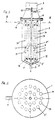
- the device according to the invention has an essentially cylindrical container 1, which tapers conically in its lower region 2 and at its deepest point has a feed opening 3 for the mixture to be separated. At the upper end of the container 1 there is an outlet opening 4 for the liquid phase enriched with the particles to be retained.
- an essentially cylindrical sieve or filter body 5 is arranged, which consists of several sieve or filter tubes 14 connected to a common collecting space 15, the through openings 5 '' of which have a free passage width, which is the diameter of the particles to be retained exceeds.
- the sieve or filter body 5 passes through a cover 6 made of flexible material and can be set into vibrations by means of an oscillation generator 7, the oscillation amplitude and oscillation frequency of which can be set and regulated by means not shown.
- an oscillation generator 7 the oscillation amplitude and oscillation frequency of which can be set and regulated by means not shown.
- a discharge line 8 for the liquid freed of the particles to be retained.
- the lower region 5 'of the sieve or filter body 5 is spaced from the lower region 2 of the container 1 and is conical in the same sense as this.
- both the outer wall of the container 1 and the sieve or filter body 5 have a cylindrical shape in all the illustrated embodiments, this shape can be modified appropriately in various ways depending on the requirements of the individual case.
- a plurality of thin sieve or filter tubes 14 with parallel openings spaced parallel to one another are provided with through openings 5 ′′, the inner space of which is connected to a common collecting space 15 which is connected to the discharge opening 8 for the the phase to be retained communicates free phase.
- the lower ends of the sieve and filter tubes 14 are inserted into associated openings 17 of a plate 16, while their upper ends are closed by plugs 18.
- Such thin sieve or filter tubes 14 can also be so-called hollow fibers, which can be combined to form larger units (so-called multiple tube modules) and result in correspondingly large filter surfaces.
- the mixture to be separated is introduced into the container 1 via the inlet opening 3 and the sieve or filter body 5 is set into vibrations by means of the vibration generator 7 via the connecting rod 19 such that their amplitude and frequency prevent the particles to be retained from passing through the through openings of the sieve - or filter tubes 14 prevented.
- the phase freed from the particles to be retained can reach the interior of the sieve or filter tubes 14 through the passage openings (see arrows P).
- the phase freed from the particles to be retained is then discharged via the discharge opening 8.
- the phase enriched with the particles to be retained emerges from the container 1 via the discharge opening.
- the sieve or filter body 5 is suspended from the cover 6 made of elastic material, with no further support being often required within the container 1. Since the vibration amplitude transmitted via the connecting rod 19 does not exceed the elastic limit of the cover material, the connecting rod 19 can be firmly connected to the cover 6, so that only the discharge opening 8 for the phase freed from the particles to be retained must be passed tightly through the cover 6. This means that there is no need for a seal between a moving part and a stationary part, which is particularly important for devices to be operated in a sterile manner.
- the through openings 5 ′′ of the sieve or filter tubes 14 are each exaggerated in size and in reality only have a diameter of usually less than 100 ⁇ m.
- the vibration generator 7 has control devices (not shown) for setting and controlling both the frequency and the amplitude of the vibrations. As a result, the retention effect of the device can be adapted to the requirements.
- the vibrations of the sieve or filter body 5 also largely prevent the particles to be retained from settling on the sieve or filter body 5, so that the passage openings 5 ′′ remain free for the passage of the carrier phase.
Landscapes
- Chemical & Material Sciences (AREA)
- Chemical Kinetics & Catalysis (AREA)
- Physics & Mathematics (AREA)
- Geometry (AREA)
- Filtering Of Dispersed Particles In Gases (AREA)
- Gas Separation By Absorption (AREA)
- Combined Means For Separation Of Solids (AREA)
- Apparatus Associated With Microorganisms And Enzymes (AREA)
- Separation Using Semi-Permeable Membranes (AREA)
- Separating Particles In Gases By Inertia (AREA)
- Filtration Of Liquid (AREA)
Claims (3)
- Dispositif pour séparer un liquide et/ou un gaz d'un mélange liquide ou gazeux contenant des particules à l'état dispersé, dispositif comprenant un réservoir (1) recevant le mélange, un corps de tamis ou de filtre (5), essentiellement cylindrique, imperméable à des particules à retenir et ayant une dimension minimale prédéterminée, ce corps de filtre étant soumis à l'action du mélange, ainsi que des dispositifs pour évacuer le liquide ou les gaz traversants, le ou les corps de tamis ou de filtre (5) étant relié(s) à un générateur de vibrations (7), pour générer des vibrations ayant une direction d'oscillation parallèle à la surface du filtre, ces corps de filtre étant placés verticalement dans le réservoir (1), ce dernier ayant, de préférence dans sa partie inférieure (2), un orifice d'alimentation (3) du mélange liquide et/ou gazeux et un orifice d'évacuation (8), de préférence dans sa partie supérieure, pour le liquide et/ou le gaz libéré des particules à retenir, dispositif caractérisé en ce que le corps de tamis ou de filtre (5) se compose de plusieurs tubes de tamis ou de filtre (14), parallèles, écartés les uns des autres, reliés par leur extrémité inférieure à une chambre collectrice commune (15) et ayant intérieurement des inserts (9) pour créer un effet de pompage, ces inserts ayant des orifices traversants (10) allant en diminuant vers l'orifice de sortie (8), les tubes de tamis ou de filtre (14) étant munis de mailles (5'') dont l'ouverture libre dépasse le diamètre des particules à retenir et les tubes de tamis ou de filtre (14) étant mis en vibrations par le générateur de vibrations (7) pour éviter, au moins dans une large mesure, le passage des particules à travers les mailles (5'') de dimensions beaucoup plus grandes.
- Dispositif selon la revendication 1, caractérisé en ce que l'orifice d'alimentation (3) et/ou l'orifice d'évacuation (8) sont munis d'un clapet anti-retour (11, 12, 13).
- Dispositif selon les revendications 1 et 2, caractérisé en ce que le générateur de vibrations (7) est muni de dispositifs pour régler et réguler l'amplitude et/ou la fréquence des oscillations.
Applications Claiming Priority (2)
| Application Number | Priority Date | Filing Date | Title |
|---|---|---|---|
| AT0164886A AT386965B (de) | 1986-06-17 | 1986-06-17 | Vorrichtung zum abscheiden von fluessigkeit und/oder gas aus einem schwebstoff-fluessigkeitoder schwebstoff-gas-gemisch |
| AT1648/86 | 1986-06-17 |
Publications (3)
| Publication Number | Publication Date |
|---|---|
| EP0249893A2 EP0249893A2 (fr) | 1987-12-23 |
| EP0249893A3 EP0249893A3 (en) | 1988-07-27 |
| EP0249893B1 true EP0249893B1 (fr) | 1993-03-17 |
Family
ID=3517965
Family Applications (1)
| Application Number | Title | Priority Date | Filing Date |
|---|---|---|---|
| EP87108460A Expired - Lifetime EP0249893B1 (fr) | 1986-06-17 | 1987-06-11 | Dispositif de séparation d'un liquide et/ou un gaz d'un mélange |
Country Status (6)
| Country | Link |
|---|---|
| US (1) | US4828719A (fr) |
| EP (1) | EP0249893B1 (fr) |
| JP (1) | JPS63185418A (fr) |
| AT (2) | AT386965B (fr) |
| DE (1) | DE3784782D1 (fr) |
| ES (1) | ES2038972T3 (fr) |
Families Citing this family (5)
| Publication number | Priority date | Publication date | Assignee | Title |
|---|---|---|---|---|
| AT386837B (de) * | 1986-03-06 | 1988-10-25 | Chemap Ag | Vorrichtung zur kultivierung von biokatalysatoren |
| US5098584A (en) * | 1990-08-31 | 1992-03-24 | City Management Corporation | Method for separating oils from scum |
| GB0913318D0 (en) | 2009-07-31 | 2009-09-02 | Univ Loughborough | Process |
| US20140251143A1 (en) * | 2013-03-08 | 2014-09-11 | Donaldson Company, Inc. | Filtration system for a gas turbine air intake and methods |
| DE102017212768A1 (de) * | 2017-07-25 | 2019-01-31 | Robert Bosch Gmbh | Flüssigkeitsfilter und Tankfiltersystem mit einem Flüssigkeitsfilter |
Citations (3)
| Publication number | Priority date | Publication date | Assignee | Title |
|---|---|---|---|---|
| CH602162A5 (en) * | 1976-11-10 | 1978-07-31 | Chemap Ag | Sepn. of solids suspended in liq. |
| WO1986007284A1 (fr) * | 1985-06-12 | 1986-12-18 | Public Health Laboratory Service Board | Perfectionnements apportes a des filtres |
| WO1987005322A1 (fr) * | 1986-03-06 | 1987-09-11 | Chemap Ag | Procede et dispositif pour le traitement d'un melange liquide contenant un biocatalyseur ou des particules comparables |
Family Cites Families (16)
| Publication number | Priority date | Publication date | Assignee | Title |
|---|---|---|---|---|
| CA535572A (fr) * | 1957-01-08 | W. Ziegenbusch Carl | Traitement de matieres thixotropiques | |
| FR1130754A (fr) * | 1955-08-22 | 1957-02-12 | Filtre télescopique et perfectionnement aux filtres à manchons en toile | |
| US3002915A (en) * | 1958-08-18 | 1961-10-03 | Exxon Research Engineering Co | Filtration method |
| DE1461460A1 (de) * | 1964-08-04 | 1969-04-10 | Reiter Dipl Ing Anton | Innenbeaufschlagtes Roehrenbuendelfilter mit senkrechten festangeordneten oder loesbaren Filtereinsaetzen und Vibrationseinrichtung |
| US3478883A (en) * | 1967-04-13 | 1969-11-18 | Amsalco Inc | Acoustic filtration apparatus |
| BR6806687D0 (pt) * | 1968-02-26 | 1973-04-12 | P Strojirny | Peneira vibratil aperfeicoada para classificacao de suspensoes liquidas e de materiais solidos |
| JPS548906B1 (fr) * | 1969-05-21 | 1979-04-19 | ||
| US3622004A (en) * | 1969-11-06 | 1971-11-23 | Chandler Evans Inc | Recirculating wash flow filter |
| US3664507A (en) * | 1970-04-15 | 1972-05-23 | Selas Corp Of America | Filter tubes in a resilient holder |
| US3766059A (en) * | 1970-12-28 | 1973-10-16 | Toshin Science Co | Filtering method and a filtering machine therefor |
| DE2225057A1 (de) * | 1971-12-27 | 1973-07-12 | Dover Corp | Filter |
| JPS5126665A (en) * | 1974-08-29 | 1976-03-05 | Kinzoku Giken Kk | Tetsu oyobi tetsugokintodotono tantsukigokin |
| SU695677A1 (ru) * | 1976-10-07 | 1979-11-05 | Всесоюзный Государственный Ордена Трудового Красного Знамени Головной Проектно-Изыскательский И Научно-Исследовательский Институт "Гипроводхоз" | Акустический фильтр |
| US4136035A (en) * | 1977-07-26 | 1979-01-23 | Bogomolov Boris N | Apparatus for dehydration of continuously fed flow of suspension |
| CH625130A5 (en) * | 1977-11-08 | 1981-09-15 | Chemap Ag | Process for filtration with the addition of filter aids and use thereof |
| US4267039A (en) * | 1977-12-05 | 1981-05-12 | Ecodyne Corporation | Fluid filtration method and apparatus |
-
1986
- 1986-06-17 AT AT0164886A patent/AT386965B/de not_active IP Right Cessation
-
1987
- 1987-06-11 AT AT87108460T patent/ATE86876T1/de active
- 1987-06-11 EP EP87108460A patent/EP0249893B1/fr not_active Expired - Lifetime
- 1987-06-11 ES ES198787108460T patent/ES2038972T3/es not_active Expired - Lifetime
- 1987-06-11 DE DE8787108460T patent/DE3784782D1/de not_active Expired - Fee Related
- 1987-06-17 US US07/063,254 patent/US4828719A/en not_active Expired - Lifetime
- 1987-06-17 JP JP62152390A patent/JPS63185418A/ja active Pending
Patent Citations (3)
| Publication number | Priority date | Publication date | Assignee | Title |
|---|---|---|---|---|
| CH602162A5 (en) * | 1976-11-10 | 1978-07-31 | Chemap Ag | Sepn. of solids suspended in liq. |
| WO1986007284A1 (fr) * | 1985-06-12 | 1986-12-18 | Public Health Laboratory Service Board | Perfectionnements apportes a des filtres |
| WO1987005322A1 (fr) * | 1986-03-06 | 1987-09-11 | Chemap Ag | Procede et dispositif pour le traitement d'un melange liquide contenant un biocatalyseur ou des particules comparables |
Also Published As
| Publication number | Publication date |
|---|---|
| US4828719A (en) | 1989-05-09 |
| DE3784782D1 (de) | 1993-04-22 |
| EP0249893A3 (en) | 1988-07-27 |
| ATE86876T1 (de) | 1993-04-15 |
| ATA164886A (de) | 1988-04-15 |
| ES2038972T3 (es) | 1993-08-16 |
| EP0249893A2 (fr) | 1987-12-23 |
| AT386965B (de) | 1988-11-10 |
| JPS63185418A (ja) | 1988-08-01 |
Similar Documents
| Publication | Publication Date | Title |
|---|---|---|
| EP0262398B1 (fr) | Filtre à pré-couche | |
| DE2323996A1 (de) | Geraet und verfahren zum absondern der traegerfluessigkeit von in ihr suspendierten teilchen | |
| DE3117712A1 (de) | Verfahren und vorrichtung zur druckfilterung eines filtrates | |
| EP1592489A2 (fr) | Dispositif de filtration et procede de filtration | |
| DE3023886A1 (de) | Verfahren und vorrichtung zum be- und verarbeiten von materialien, insbesondere von fliessfaehigen feststoffgemischen und dispersionen, durch schwingende werkzeuge | |
| DE1507839A1 (de) | Verfahren und Vorrichtung zum Reinigen von Filtermitteln | |
| EP2185262B1 (fr) | Filtre comprenant des moyens de vibration | |
| DE2146838C3 (de) | Verfahren und Vorrichtung zum Filtrieren von Flüssigkeiten | |
| EP0249893B1 (fr) | Dispositif de séparation d'un liquide et/ou un gaz d'un mélange | |
| DE69932005T2 (de) | Vorrichtung und Verfahren zur Regeneration von Medien zur Flüssigkeitsbehandlung | |
| DE2449817B2 (de) | Verfahren und einrichtung zur filtration fluessiger medien | |
| DE102005027509B4 (de) | Vorrichtung und Filterelement zum Filtern von Fluid-Feststoff-Gemischen | |
| DE3782742T2 (de) | Verfahren und vorrichtung zur regeneration einer dynamischen membran in eine fluessigkeitstrennanlage. | |
| EP4245395B1 (fr) | Dispositif et procédé d'échange continu de gaz dans un flux d'un mélange de fluides | |
| EP0465840A1 (fr) | Dispositif de filtration, notamment pour la séparation de grosses particules d'une suspension de lubrifiant et leur utilisation | |
| EP0087040A2 (fr) | Séparateur vibrant pour broyeur agitateur à bulles | |
| DE1303735C2 (de) | Verfahren zur kontinuierlichen klassierung, filtrierung oder fraktionierung von suspensionen oder feststoffbeladenen gasen unter druck und hierzu dienende vorrichtung | |
| DE10047431B4 (de) | Druckfilter mit Vibrationsantrieb | |
| DE3605065A1 (de) | Separationsvorrichtung | |
| DD252768A5 (de) | Verfahren und vorrichtung zum waschen und/oder filtern u./o. sieben eines in form einer truebe vorliegenden mineralgemisches unterschiedl. koernungen in einer drehbaren und perforierten trommel | |
| CH602162A5 (en) | Sepn. of solids suspended in liq. | |
| DE19528775C1 (de) | Filtervorrichtung | |
| DE1442538C2 (de) | Verfahren zur kontinuierlichen Klassierung, Filtrierung oder Fraktionierung von Suspensionen oder feststoffbeladenen Gasen unter Druck und hierzu dienende Vorrichtung | |
| EP1877155A1 (fr) | Dispositif et procede de separation de matieres solides et de liquides | |
| DE9417638U1 (de) | Kerzenfiltervorrichtung für die Bierfiltration |
Legal Events
| Date | Code | Title | Description |
|---|---|---|---|
| PUAI | Public reference made under article 153(3) epc to a published international application that has entered the european phase |
Free format text: ORIGINAL CODE: 0009012 |
|
| AK | Designated contracting states |
Kind code of ref document: A2 Designated state(s): AT BE CH DE ES FR GB IT LI NL SE |
|
| PUAL | Search report despatched |
Free format text: ORIGINAL CODE: 0009013 |
|
| AK | Designated contracting states |
Kind code of ref document: A3 Designated state(s): AT BE CH DE ES FR GB IT LI NL SE |
|
| 17P | Request for examination filed |
Effective date: 19880910 |
|
| 17Q | First examination report despatched |
Effective date: 19900913 |
|
| RTI1 | Title (correction) | ||
| GRAA | (expected) grant |
Free format text: ORIGINAL CODE: 0009210 |
|
| ITF | It: translation for a ep patent filed | ||
| AK | Designated contracting states |
Kind code of ref document: B1 Designated state(s): AT BE CH DE ES FR GB IT LI NL SE |
|
| REF | Corresponds to: |
Ref document number: 86876 Country of ref document: AT Date of ref document: 19930415 Kind code of ref document: T |
|
| GBT | Gb: translation of ep patent filed (gb section 77(6)(a)/1977) |
Effective date: 19930324 |
|
| REF | Corresponds to: |
Ref document number: 3784782 Country of ref document: DE Date of ref document: 19930422 |
|
| ET | Fr: translation filed | ||
| PG25 | Lapsed in a contracting state [announced via postgrant information from national office to epo] |
Ref country code: LI Effective date: 19930630 Ref country code: CH Effective date: 19930630 |
|
| PLBE | No opposition filed within time limit |
Free format text: ORIGINAL CODE: 0009261 |
|
| STAA | Information on the status of an ep patent application or granted ep patent |
Free format text: STATUS: NO OPPOSITION FILED WITHIN TIME LIMIT |
|
| REG | Reference to a national code |
Ref country code: CH Ref legal event code: PL |
|
| 26N | No opposition filed | ||
| ITTA | It: last paid annual fee | ||
| EAL | Se: european patent in force in sweden |
Ref document number: 87108460.4 |
|
| REG | Reference to a national code |
Ref country code: GB Ref legal event code: 732E |
|
| NLS | Nl: assignments of ep-patents |
Owner name: B. BRAUN BIOTECH INTERNATIONAL GMBH |
|
| NLT1 | Nl: modifications of names registered in virtue of documents presented to the patent office pursuant to art. 16 a, paragraph 1 |
Owner name: BITEC ENTERPRISE AG |
|
| REG | Reference to a national code |
Ref country code: FR Ref legal event code: CD |
|
| REG | Reference to a national code |
Ref country code: FR Ref legal event code: CD |
|
| REG | Reference to a national code |
Ref country code: ES Ref legal event code: PC2A Owner name: B. BRAUN BIOTECH INTERNATIONAL GMBH. |
|
| REG | Reference to a national code |
Ref country code: FR Ref legal event code: TP |
|
| BECH | Be: change of holder |
Free format text: 960312 B. *BRAUN BIOTECH INTERNATIONAL G.M.B.H. |
|
| PGFP | Annual fee paid to national office [announced via postgrant information from national office to epo] |
Ref country code: GB Payment date: 19990406 Year of fee payment: 13 |
|
| PGFP | Annual fee paid to national office [announced via postgrant information from national office to epo] |
Ref country code: FR Payment date: 19990420 Year of fee payment: 13 |
|
| PGFP | Annual fee paid to national office [announced via postgrant information from national office to epo] |
Ref country code: SE Payment date: 19990621 Year of fee payment: 13 Ref country code: BE Payment date: 19990621 Year of fee payment: 13 Ref country code: AT Payment date: 19990621 Year of fee payment: 13 |
|
| PGFP | Annual fee paid to national office [announced via postgrant information from national office to epo] |
Ref country code: NL Payment date: 19990622 Year of fee payment: 13 |
|
| PGFP | Annual fee paid to national office [announced via postgrant information from national office to epo] |
Ref country code: ES Payment date: 19990623 Year of fee payment: 13 |
|
| PG25 | Lapsed in a contracting state [announced via postgrant information from national office to epo] |
Ref country code: GB Free format text: LAPSE BECAUSE OF NON-PAYMENT OF DUE FEES Effective date: 20000611 Ref country code: AT Free format text: LAPSE BECAUSE OF NON-PAYMENT OF DUE FEES Effective date: 20000611 |
|
| PG25 | Lapsed in a contracting state [announced via postgrant information from national office to epo] |
Ref country code: SE Free format text: LAPSE BECAUSE OF NON-PAYMENT OF DUE FEES Effective date: 20000612 Ref country code: ES Free format text: THE PATENT HAS BEEN ANNULLED BY A DECISION OF A NATIONAL AUTHORITY Effective date: 20000612 |
|
| PG25 | Lapsed in a contracting state [announced via postgrant information from national office to epo] |
Ref country code: BE Free format text: LAPSE BECAUSE OF NON-PAYMENT OF DUE FEES Effective date: 20000630 |
|
| BERE | Be: lapsed |
Owner name: B. BRAUN BIOTECH INTERNATIONAL G.M.B.H. Effective date: 20000630 |
|
| PG25 | Lapsed in a contracting state [announced via postgrant information from national office to epo] |
Ref country code: NL Free format text: LAPSE BECAUSE OF NON-PAYMENT OF DUE FEES Effective date: 20010101 |
|
| GBPC | Gb: european patent ceased through non-payment of renewal fee |
Effective date: 20000611 |
|
| EUG | Se: european patent has lapsed |
Ref document number: 87108460.4 |
|
| PG25 | Lapsed in a contracting state [announced via postgrant information from national office to epo] |
Ref country code: FR Free format text: LAPSE BECAUSE OF NON-PAYMENT OF DUE FEES Effective date: 20010228 |
|
| NLV4 | Nl: lapsed or anulled due to non-payment of the annual fee |
Effective date: 20010101 |
|
| REG | Reference to a national code |
Ref country code: FR Ref legal event code: ST |
|
| REG | Reference to a national code |
Ref country code: ES Ref legal event code: FD2A Effective date: 20020204 |
|
| PGFP | Annual fee paid to national office [announced via postgrant information from national office to epo] |
Ref country code: DE Payment date: 20020630 Year of fee payment: 16 |
|
| PG25 | Lapsed in a contracting state [announced via postgrant information from national office to epo] |
Ref country code: DE Free format text: LAPSE BECAUSE OF NON-PAYMENT OF DUE FEES Effective date: 20040101 |
|
| PG25 | Lapsed in a contracting state [announced via postgrant information from national office to epo] |
Ref country code: IT Free format text: LAPSE BECAUSE OF NON-PAYMENT OF DUE FEES;WARNING: LAPSES OF ITALIAN PATENTS WITH EFFECTIVE DATE BEFORE 2007 MAY HAVE OCCURRED AT ANY TIME BEFORE 2007. THE CORRECT EFFECTIVE DATE MAY BE DIFFERENT FROM THE ONE RECORDED. Effective date: 20050611 |