EP0250105A1 - Procéde et dispositif de radionavigation - Google Patents
Procéde et dispositif de radionavigation Download PDFInfo
- Publication number
- EP0250105A1 EP0250105A1 EP87304601A EP87304601A EP0250105A1 EP 0250105 A1 EP0250105 A1 EP 0250105A1 EP 87304601 A EP87304601 A EP 87304601A EP 87304601 A EP87304601 A EP 87304601A EP 0250105 A1 EP0250105 A1 EP 0250105A1
- Authority
- EP
- European Patent Office
- Prior art keywords
- channels
- ranging signal
- mobile
- frequency spectrum
- signals
- Prior art date
- Legal status (The legal status is an assumption and is not a legal conclusion. Google has not performed a legal analysis and makes no representation as to the accuracy of the status listed.)
- Withdrawn
Links
- 238000004891 communication Methods 0.000 claims abstract description 31
- 230000006854 communication Effects 0.000 claims abstract description 31
- 230000001413 cellular effect Effects 0.000 claims abstract description 18
- 238000001228 spectrum Methods 0.000 claims abstract description 15
- 238000000034 method Methods 0.000 claims description 10
- 230000003595 spectral effect Effects 0.000 claims description 10
- 230000005540 biological transmission Effects 0.000 claims description 5
- 238000010586 diagram Methods 0.000 description 8
- 230000004048 modification Effects 0.000 description 5
- 238000012986 modification Methods 0.000 description 5
- 230000004044 response Effects 0.000 description 2
- 230000000007 visual effect Effects 0.000 description 2
- 230000008859 change Effects 0.000 description 1
- 230000001419 dependent effect Effects 0.000 description 1
- 238000001914 filtration Methods 0.000 description 1
- 239000004973 liquid crystal related substance Substances 0.000 description 1
- 230000008569 process Effects 0.000 description 1
Images


Classifications
-
- H—ELECTRICITY
- H04—ELECTRIC COMMUNICATION TECHNIQUE
- H04W—WIRELESS COMMUNICATION NETWORKS
- H04W64/00—Locating users or terminals or network equipment for network management purposes, e.g. mobility management
-
- H—ELECTRICITY
- H04—ELECTRIC COMMUNICATION TECHNIQUE
- H04B—TRANSMISSION
- H04B7/00—Radio transmission systems, i.e. using radiation field
- H04B7/14—Relay systems
- H04B7/15—Active relay systems
- H04B7/185—Space-based or airborne stations; Stations for satellite systems
- H04B7/1853—Satellite systems for providing telephony service to a mobile station, i.e. mobile satellite service
- H04B7/18545—Arrangements for managing station mobility, i.e. for station registration or localisation
- H04B7/18547—Arrangements for managing station mobility, i.e. for station registration or localisation for geolocalisation of a station
- H04B7/1855—Arrangements for managing station mobility, i.e. for station registration or localisation for geolocalisation of a station using a telephonic control signal, e.g. propagation delay variation, Doppler frequency variation, power variation, beam identification
-
- H—ELECTRICITY
- H04—ELECTRIC COMMUNICATION TECHNIQUE
- H04J—MULTIPLEX COMMUNICATION
- H04J3/00—Time-division multiplex systems
- H04J3/02—Details
- H04J3/06—Synchronising arrangements
- H04J3/0635—Clock or time synchronisation in a network
- H04J3/0682—Clock or time synchronisation in a network by delay compensation, e.g. by compensation of propagation delay or variations thereof, by ranging
Definitions
- This invention relates to a method and apparatus for radio location.
- a method and apparatus may be employed for example with a satellite communication system.
- Another such method and apparatus may be employed for example with a cellular radio system.
- a navigational fix may be obtained by measuring the time taken for a ranging message to travel from a vehicle requiring the fix to each of a plurality of stations at fixed positions, such as satellites in geostationary orbit.
- a unambiguous fix of high resolution can only be obtained utilising ranging messages having a wide band and substantially continuous frequency spectrum which messages accordingly make uneconomic use of available frequency bands.
- the object of the invention is provide a radio location system in which economic use of available frequency bands is made.
- the invention is applied to a communication system having a plurality of channels, such as for voice communication, and utilises the frequency band of that communication system for obtaining a navigational fix.
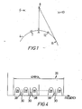
- a communication system in which the invention may be embodied comprises a base station 2 at a fixed position on the surface of the earth 4, a plurality of satellites 6, 8, 10 (only three being shown although more may be provided), and a plurality of mobile stations carried on sea-borne vehicles, of which one is indicated at 12.
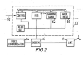
- the mobile station comprises conventional voice communication circuitry 14 coupled via a modem 16 (and other conventional circuitry not shown) to a directional antenna 18 for the transmission and reception of voice communication signals to and from land-based public telephone systems via the satellites and the base station 2.
- the base station includes a number of narrow beam width antennae 20, one for each satellite, coupled via respective modems 22 (and other conventional circuitry not shown) to voice communication circuitry 24 which is connected to the public switched telephone network.
- the system is assigned a band of frequencies which, in the example under discussion, will be taken to have a bandwidth of 4 MHz.
- This frequency band is indicated in Figure 4 at 26 and, in the example under discussion, provides for a number of voice communication channels 28 so spaced as to leave guard bands 30 between them.
- the base station When one of the mobile stations wishes to make a telephone call, it sends a request signal to the base station which then assigns one of the vacant voice channels 28 for this purpose. This operation is entirely conventional and need not be described further.
- the mobile station 12 is provided with a navigational device 32 which is coupled to the modem 16 and the base station 2 is provided with a navigational device 34 which is coupled to the modem 22, in accordance with a preferred embodiment of the invention.
- control circuit 50 When a station 12 requires a navigational fix, an appropriate instruction is input to control circuit 50 on line 52 and this causes circuit 54 to generate a request signal which is transmitted to the base station 22 via the modem 16, antenna 18 and the satellites.
- This navigational request signal is received by one of the antennae 20 and modems 22 and supplied to the navigational unit 34.
- control circuit 56 of unit 34 instructs circuit 58 to allocate a vacant one of the channels 28.
- Circuit 60 then generates a narrow band ranging message which is transmitted to a selected one of the satellites, say satellite 8, via the associated antenna 20 and modem 22.
- the satellite 8 retransmits the ranging message in the allocated channel 28 to the mobile station 12 which has requested the fix.
- control circuit 50 causes circuit 62 to regenerate and retransmit the narrow band ranging message after a short fixed delay.
- the retransmitted ranging message is received by the satellite 8), and the satellite 8 retransmits it back to the base station 2 in which it is supplied to a calculation circuit 64.
- the narrow band ranging messages are transmitted repeatedly, for a predetermined time, by the base station.
- Each satellite can only communicate with the stations in the direct line of sight.
- the nearest point to the satellite 8 on the earth's surface is point A and the most distant point on the earth's surface in the direct line of sight from the satellite 8 is the point B which is on a circle centered at point A.
- the distance from point A to the satellite 8 is approximately 36,000 km and the distance from point B to satellite 8 is approximately 42,000 km.
- the mobile station 12 is shown in Figure 1 as being at a position somewhere between points A and B so that the round-trip time taken for a ranging message to travel from the satellite 8 to the station 12 and back to the satellite 8 will be between 240 milliseconds and 280 milliseconds plus the above mentioned short fixed delay, dependent upon the actual position of the station 12.
- the round-trip time is an indication of the position of the station 12 between the point A and the circle on which point B lies.
- the repetition rate of the ranging message should be no greater than 25 Hz (i.e. no more than one ranging message every 40 milliseconds) to avoid ambiguity in the location of the station 12.
- the above mentioned repetition rate of the narrow band ranging message is approximately 25 Hz.
- the procedure is repeated utilising one or more of the other satellites so that the calculation circuit may obtain a fix on the station 12 in known manner.
- the narrow band ranging messages can only provide a fix of low resolution, although this fix is unambiguous.
- the control circuit 56 is arranged to cause circuit 68 to generate a wide band ranging message which is so constructed and repeated that its spectrum comprises a series of widely spaced narrow spikes 38 which fit in the guardbands 30 between the channels 28.
- the wide band ranging message has a frequency spectrum of comb structure.
- the wide band ranging message is repeated at a frequency equal to the spacing between the voice signal guardbands, eg. 25 KHz, or once every 40 microseconds. Accordingly, this signal alone, whilst providing high resolution, would not provide an unambiguous fix.
- the resolution of the narrow band signal is sufficient to resolve the ambiguity of the wideband fix.
- the wide band ranging message is firstly repeatedly transmitted from the base station 2 via a selected one of the satellites, such as satellite 8 to the mobile station 12 where it is received and re-transmitted after a short fixed delay by circuit 66 under control of control circuit 50 so that the round-trip time between satellite 8 and station 12 may be measured in calculation circuit 64.
- the process is repeated using one or more of the other satellites.
- the calculation circuit 64 obtains an unambiguous low resolution fix using the narrow band ranging messages and achieves high resolution using the wide band ranging messages.
- the resulting fix may be transferred to store 70 from which it may be read out and transmitted to the station 12 and/or otherwise used.
- the wide band ranging message may have a chip rate of 3.175 MHz and a sequence length of 127 chips, thus giving a repetition rate of 25 KHz.
- the total band width of such a signal would be 6.35 MHZ but the end portions may be filtered out.
- the time resolution which can be achieved with such a signal is 0.03 microseconds which is equivalent to a resolution of 10 metres in the round trip distance between the satellite and the station 12 which, in turn, allows a resolution of approximately 5 metres in the one-way distance.
- the narrow band signal may comprise the same sequence as the wide band signal but having a chip rate of 3.175 KHz giving a band width of 6.5 KHz.
- an accurate fix is obtained by transmitting a narrow band ranging signal which provides an unambiguous fix but with low resolution and a wide band ranging message which provides the required high resolution but with 1000 fold ambiguity, which is resolved by the narrow band signal.
- the wideband signal could not alone provide an unambiguous fix.
- both of these signals are transmitted and the fix obtained utilising an existing satellite communication system without the need for the allocation of any special frequency band whatsoever.
- the apparatus 32 and 34 may be manufactured separately from the apparatus incorporated in the satellite communication system, if desired, and may be supplied as an accessory to the existing system.
- navigational units 32 and 34 shown in Figures 2 and 3 have been illustrated in block diagram form, it should be understood that these blocks do not necessarily represent individual pieces of hardware. On the contrary, these blocks are merely intended to indicate the functions to be performed in these units. Such functions may be provided by hardware or software or a combination of both.
- satellite communication systems examples include the INMARSAT system and the SPADE system.
- the communication system is such that, if not all of the channels 28 are in use, some of the channels in use will be displaced relative to the positions shown in Figure 4 so that some of the spikes shown in Figure 4 will in fact be within one or more of the channels in use.
- means may be provided in the apparatus 34 for indicating such displaced channels and means may be provided in the apparatus 32 for filtering or cancelling out those spectral lines 38 which coincide with the displaced communication channels, the transmitted lines 38 being within the guardbands as described.
- the low resolution ranging signals 42 should be transmitted within a single one of the channels 28, this is not essential.
- a special narrow frequency band outside the band 26 might be allocated, although this is not preferred.
- the narrow band signal has been transmitted first, this is not essential and, alternatively, it would be possible to transmit the wide band signal first and the narrow band signal second.
- narrow band and wide band ranging messages may be generated simultaneously or substantially simultaneously.
- the embodiment as described has been one in which ranging messages are transmitted from the base station via the satellites to the stations requiring the fix
- the invention may be embodied in other types of system, for example those in which the ranging messages would be originated by the stations requiring the fix; systems using omni-directional mobile antennas, where the return signal from mobile to base is relayed by all satellites simultaneously, discriminated by angle of arrival at base station antennas and all ranges calculated at one; or systems in which mobile does not retransmit signals at all but calculates its own position on time differences of message received from base station via multiple satellites.
- the invention has been described in connection with the satellite communication systems, it may be utilised in systems not involving satellites, such as a cellular radio system as will now be described with reference to Figures 5 to 7.
- Cellular radio systems are well known.
- an area is divided into cells 70 with which base station 71 are associated.
- each cell has one base station approximately in the centre of the cell.
- Each base station broadcasts and receives via an omni-directional antenna.
- the system is controlled by, e.g. a network control station 82 linked to the base station 71.
- a network control station 82 linked to the base station 71.
- the frequencies of the cellular radio system are arranged in the manner shown in Figure 4, that is within an overall band width of e.g. 4 mega hertz, a plurality of communication channels each having a band width of e.g 25 kilo hertz are separated by guard bands 30.
- Different radio systems may have different channel band widths and over-all system band widths.
- the system in particular the "hand-off control" in the network control station, automatically tracks the positions of the mobiles to the extent that it is known which of the cells each mobile is in.
- the position of each mobile is known to the system to a resolution of one cell area.
- the manner of operation of such a cellular radio system and the equipment required to operate it are well known in the art.
- the narrow band signal used above to resolve range ambiguities is not needed because the approximate position of each mobile is known to the cellular radio system.
- wide band ranging signals it is not necessary for wide band ranging signals to be both transmitted from a base station to a mobile and transmitted back from the mobile to the base station. Instead, a wide band ranging signal is transmitted only from the mobile.
- the wide band ranging signal is so constructed and repeated that its spectrum comprises a series of spikes 38 which fit in the guard bands 30 between the channels 28 as shown in Figure 4.
- the wide band ranging signal is detected by three base stations 71 nearest to the mobile and the position of the mobile is computed from the differences in the times of arrival of the ranging signal at the three base stations. The manner of performing that computation is known in the art of radio location.
- the cellular radio system appears to operate as if it were a telephone system.
- the user dials the number of the person he wishes to call.
- the system "knows" the identity of the mobile making the call.
- Figure 6 shows a schematic block diagram of a transceiver used in a mobile.
- the user dials the number of the person or service he uses to contact using for example a keypad 73 and signal processing and control circuitry 74 respond to that number to transmit a control signal via a transmitter 75 and an antenna 76 to establish the communication link.
- the user can talk into a microphone, the speech signals being processed and transmitted via the signal processing and control circuitry 74 and the transmitter 75.
- Voice and other control signals are received by the antenna 76 and a receiver 78 and passed to the signal processing and control circuitry 74.
- the voice signals are reproduced by a loudspeaker, the loudspeaker and the microphone being schematically indicated by the block 77.
- the transceiver is modified by the addition of a wide band ranging signal generator 79.
- a wide band ranging signal generator 79 The form of a suitable generator for producing the wide band ranging signal comprising a series of spikes 38 which fit in the guard bands 30 between the channels 38 of the cellular radio system is known in the art.
- the generator is caused to selectively send the signal to the transmitter 75 in response to an instruction transmitted from the network control station 82 via the nearest base station 71 and received by the antenna 76 receiver 78 and signal processing and control circuitry 74.
- the navigation control at the network control station transmits to the transceiver via the nearest base station 71, information representing the position of the mobile. That information is received by the antenna 76 receiver 78 and processed by the signal processing and control circuitry 74.
- a visual display unit 80 controlled by the signal processing and control unit 74 may be provided.
- the data representing the position of the user at its simplest may be merely a map reference in which case the VDU could be e.g. a liquid crystal display for displaying the map reference. It is also possible to envisage that the position information could be presented as speech.
- the only modification to a standard mobile transceiver could be merely the addition of the wide band signal generator responsive to an instruction from the signal processing and control unit 74.
- some form of visual display such as an LCD may be provided if such a display is not already provided in the transceiver.
- Some modification may be required to the signal processing and control unit such as additional logic and/or modified software.
- each station comprises an antenna 87 a transmitter 86, a receiver 81 and a modulator 85. All those items, and other items not shown are present, unmodified, in the base station.
- each base station is additionally provided with means 88 for determining the times of arrival of ranging signals at the base stations. For that purpose all the base stations receive via for example telephone lines 89 timing signals representing a standard time which is the same for all base stations.
- the means 88 which receives the ranging signal from the receiver 81 demodulates the ranging signal and compares its time of arrival with the standard time represented by the standard timing signal.
- Means 88 may include a delay lock loop as known in the art for demodulating the ranging signal and determining its time of arrival.
- the base stations 71, 71b and 71c are identical. They are all coupled via suitable communication channels e.g. telephone lines 90 to the network control station 82.
- the network control station 82 is provided for the purposes of the present invention additionally with a navigation control unit 83 which may comprise a computer specifically for navigation control. Alternatively, the navigation control unit 83 may be implemented by computing equipment already present in the network control station in which case the only change to the network control station would be a modification of the software.
- the navigation control unit 83 calculates, in known manner, the position of the mobile using the differences in times of arrival of the ranging signals at the base station 71a, 71b and 71c and transmits via the base station e.g. 71a nearest to the mobiIe data representing the position of the mobile.
Landscapes
- Engineering & Computer Science (AREA)
- Computer Networks & Wireless Communication (AREA)
- Signal Processing (AREA)
- Physics & Mathematics (AREA)
- Astronomy & Astrophysics (AREA)
- Aviation & Aerospace Engineering (AREA)
- General Physics & Mathematics (AREA)
- Radio Relay Systems (AREA)
- Mobile Radio Communication Systems (AREA)
Applications Claiming Priority (2)
| Application Number | Priority Date | Filing Date | Title |
|---|---|---|---|
| GB08612561A GB2191054A (en) | 1986-05-22 | 1986-05-22 | Combined communication and location system |
| GB8612561 | 1986-05-22 |
Publications (1)
| Publication Number | Publication Date |
|---|---|
| EP0250105A1 true EP0250105A1 (fr) | 1987-12-23 |
Family
ID=10598320
Family Applications (1)
| Application Number | Title | Priority Date | Filing Date |
|---|---|---|---|
| EP87304601A Withdrawn EP0250105A1 (fr) | 1986-05-22 | 1987-05-22 | Procéde et dispositif de radionavigation |
Country Status (2)
| Country | Link |
|---|---|
| EP (1) | EP0250105A1 (fr) |
| GB (1) | GB2191054A (fr) |
Cited By (12)
| Publication number | Priority date | Publication date | Assignee | Title |
|---|---|---|---|---|
| EP0320913A3 (fr) * | 1987-12-18 | 1990-08-16 | Nokia-Mobira Oy | Procédé de localisation d'une station mobile ainsi qu'une station mobile et une station de base pour la mise en oeuvre du procédé |
| EP0341738A3 (fr) * | 1988-05-13 | 1991-01-23 | AEG MOBILE COMMUNICATION GmbH | Dispositif de détermination de la position propre, notamment pour des véhicules |
| GB2239758A (en) * | 1990-01-04 | 1991-07-10 | Stc Plc | Navigation facility for cellular telephones |
| EP0470272A1 (fr) * | 1990-08-06 | 1992-02-12 | Ascom Radiocom AG | Procédé de localisation d'un émetteur mobile |
| JPH04267638A (ja) * | 1990-11-07 | 1992-09-24 | Hughes Aircraft Co | 拡散スペクトル送信を使用した改良セル電話サービス |
| EP0489794A4 (en) * | 1987-01-27 | 1993-06-09 | Advanced Systems Research Pty. Ltd. | Improvements in a spread-spectrum multiplexed transmission system |
| EP0571104A3 (fr) * | 1992-05-21 | 1994-03-09 | Ibm | |
| EP0582073A3 (en) * | 1992-08-03 | 1994-07-20 | Motorola Inc | Remote position determination |
| FR2721459A1 (fr) * | 1994-06-21 | 1995-12-22 | Alcatel Mobile Comm France | Procédé de radiolocalisation d'un mobile à l'aide d'un satellite, dispositif de radiolocalisation, et procédé d'émission correspondants. |
| NL1005179C2 (nl) * | 1997-02-04 | 1998-08-06 | Koninkl Kpn Nv | Systeem voor lokatiebepaling van een transponder. |
| EP1146350A1 (fr) * | 1994-03-25 | 2001-10-17 | Qualcomm Incorporated | Méthode de détermination d'une position et son utilisation dans un système cellulaire analogique |
| GB2442515A (en) * | 2006-10-06 | 2008-04-09 | Motorola Inc | Ranging information indicator |
Families Citing this family (3)
| Publication number | Priority date | Publication date | Assignee | Title |
|---|---|---|---|---|
| US5126733A (en) * | 1989-05-17 | 1992-06-30 | Motorola, Inc. | Location information polling in a communication system |
| GB2321831B (en) * | 1994-07-22 | 1999-02-17 | Int Mobile Satellite Org | Satellite communication method and apparatus |
| US6560461B1 (en) | 1997-08-04 | 2003-05-06 | Mundi Fomukong | Authorized location reporting paging system |
Citations (4)
| Publication number | Priority date | Publication date | Assignee | Title |
|---|---|---|---|---|
| DE3029466A1 (de) * | 1980-08-02 | 1982-04-08 | Franz Dipl.-Ing. 7015 Korntal-Münchingen Leitl | Fahrzeugortungssystem |
| EP0141994A1 (fr) * | 1983-09-28 | 1985-05-22 | Siemens Aktiengesellschaft | Réseau de radiotéléphonie mobile |
| DE3426851C1 (de) * | 1984-07-20 | 1985-10-17 | Deutsche Forschungs- und Versuchsanstalt für Luft- und Raumfahrt e.V., 5300 Bonn | Satelliten-Navigationssystem |
| US4596988A (en) * | 1983-06-10 | 1986-06-24 | Wanka James T | Remote controlled tracking transmitter and tracking support system |
-
1986
- 1986-05-22 GB GB08612561A patent/GB2191054A/en not_active Withdrawn
-
1987
- 1987-05-22 EP EP87304601A patent/EP0250105A1/fr not_active Withdrawn
Patent Citations (4)
| Publication number | Priority date | Publication date | Assignee | Title |
|---|---|---|---|---|
| DE3029466A1 (de) * | 1980-08-02 | 1982-04-08 | Franz Dipl.-Ing. 7015 Korntal-Münchingen Leitl | Fahrzeugortungssystem |
| US4596988A (en) * | 1983-06-10 | 1986-06-24 | Wanka James T | Remote controlled tracking transmitter and tracking support system |
| EP0141994A1 (fr) * | 1983-09-28 | 1985-05-22 | Siemens Aktiengesellschaft | Réseau de radiotéléphonie mobile |
| DE3426851C1 (de) * | 1984-07-20 | 1985-10-17 | Deutsche Forschungs- und Versuchsanstalt für Luft- und Raumfahrt e.V., 5300 Bonn | Satelliten-Navigationssystem |
Cited By (19)
| Publication number | Priority date | Publication date | Assignee | Title |
|---|---|---|---|---|
| EP0489794A4 (en) * | 1987-01-27 | 1993-06-09 | Advanced Systems Research Pty. Ltd. | Improvements in a spread-spectrum multiplexed transmission system |
| EP0320913A3 (fr) * | 1987-12-18 | 1990-08-16 | Nokia-Mobira Oy | Procédé de localisation d'une station mobile ainsi qu'une station mobile et une station de base pour la mise en oeuvre du procédé |
| EP0341738A3 (fr) * | 1988-05-13 | 1991-01-23 | AEG MOBILE COMMUNICATION GmbH | Dispositif de détermination de la position propre, notamment pour des véhicules |
| GB2239758A (en) * | 1990-01-04 | 1991-07-10 | Stc Plc | Navigation facility for cellular telephones |
| GB2239758B (en) * | 1990-01-04 | 1994-01-12 | Stc Plc | Navigation facility for cellular telephones |
| EP0470272A1 (fr) * | 1990-08-06 | 1992-02-12 | Ascom Radiocom AG | Procédé de localisation d'un émetteur mobile |
| JPH04267638A (ja) * | 1990-11-07 | 1992-09-24 | Hughes Aircraft Co | 拡散スペクトル送信を使用した改良セル電話サービス |
| EP0484918A3 (en) * | 1990-11-07 | 1993-04-14 | Hughes Aircraft Company | Improved cellular telephone service using spread spectrum transmission |
| EP0571104A3 (fr) * | 1992-05-21 | 1994-03-09 | Ibm | |
| EP0582073A3 (en) * | 1992-08-03 | 1994-07-20 | Motorola Inc | Remote position determination |
| US5666647A (en) * | 1992-08-03 | 1997-09-09 | Motorola, Inc. | Remote position determination |
| EP1146350A1 (fr) * | 1994-03-25 | 2001-10-17 | Qualcomm Incorporated | Méthode de détermination d'une position et son utilisation dans un système cellulaire analogique |
| FR2721459A1 (fr) * | 1994-06-21 | 1995-12-22 | Alcatel Mobile Comm France | Procédé de radiolocalisation d'un mobile à l'aide d'un satellite, dispositif de radiolocalisation, et procédé d'émission correspondants. |
| EP0689062A1 (fr) * | 1994-06-21 | 1995-12-27 | Alcatel Mobile Communication France | Procédé de radiolocalisation d'un mobile à l'aide d'un satellite, dispositif de radiolocalisation, et procédé d'émission correspondants |
| US5610615A (en) * | 1994-06-21 | 1997-03-11 | Alcatel Mobile Communication France | Method and device for mobile station positioning by means of a satellite, and associated transmission method |
| NL1005179C2 (nl) * | 1997-02-04 | 1998-08-06 | Koninkl Kpn Nv | Systeem voor lokatiebepaling van een transponder. |
| GB2442515A (en) * | 2006-10-06 | 2008-04-09 | Motorola Inc | Ranging information indicator |
| GB2442515B (en) * | 2006-10-06 | 2010-01-13 | Motorola Inc | Communication system and method of operation therefor |
| US8401096B2 (en) | 2006-10-06 | 2013-03-19 | Motorola Solutions, Inc. | Communication system and method of operations therefor |
Also Published As
| Publication number | Publication date |
|---|---|
| GB8612561D0 (en) | 1986-07-02 |
| GB2191054A (en) | 1987-12-02 |
Similar Documents
| Publication | Publication Date | Title |
|---|---|---|
| EP0484918B1 (fr) | Service de téléphonie cellulaire amélioré utilisant une transmission par étalement de spectre | |
| EP0779991B1 (fr) | Systeme de distribution telephonique sans fil avec transmission a diversite dans le temps et dans l'espace | |
| EP0752113B1 (fr) | Methode de determination d'une position et son utilisation dans un systeme cellulaire analogique | |
| US5225843A (en) | Method for accessing a trunked communication system | |
| US6603800B1 (en) | CDMA location | |
| JPH0629916A (ja) | 位置割り出しトランシーバ | |
| GB2215932A (en) | Radio position finding system | |
| GB2191054A (en) | Combined communication and location system | |
| AU5555294A (en) | Positioning systems utilizing mobile telephone system for correction signals | |
| EP0885543B1 (fr) | Procede et systeme de localisation | |
| Anderson et al. | Satellite-aided mobile communications: Experiments, applications, and prospects | |
| KR0135567B1 (ko) | 저궤도 위성과 글로벌 위치설정 시스템 수신기를 이용한 교통정보 서비스 시스템 및 그의 방법 | |
| JPH0761177B2 (ja) | 広域移動体通信方式 | |
| CA1310699C (fr) | Systeme d'appel telephonique sol-air et methode connexe | |
| RU82394U1 (ru) | Система радиосвязи с подвижными объектами | |
| JPH0442626A (ja) | 移動体用通信装置 | |
| HK1081750B (en) | Wireless telephone distribution system with time and space diversity transmission | |
| EP0758476A1 (fr) | Procede et systeme d'obtention d'informations provenant d'une pluralite de stations eloignees | |
| HK1118980B (en) | Wireless telephone distribution system with time and space diversity transmission | |
| HK1118982B (en) | Wireless telephone distribution system with time and space diversity transmission | |
| HK1076343B (en) | Method and system for locating a mobile subscriber in a cdma communication system | |
| JPH08275246A (ja) | 移動体通信装置 |
Legal Events
| Date | Code | Title | Description |
|---|---|---|---|
| PUAI | Public reference made under article 153(3) epc to a published international application that has entered the european phase |
Free format text: ORIGINAL CODE: 0009012 |
|
| AK | Designated contracting states |
Kind code of ref document: A1 Designated state(s): DE FR GB IT NL SE |
|
| 17P | Request for examination filed |
Effective date: 19880620 |
|
| STAA | Information on the status of an ep patent application or granted ep patent |
Free format text: STATUS: THE APPLICATION IS DEEMED TO BE WITHDRAWN |
|
| 18D | Application deemed to be withdrawn |
Effective date: 19901201 |
|
| RIN1 | Information on inventor provided before grant (corrected) |
Inventor name: BARTON, STEPHEN KINGSLEY |