EP0250177A1 - Aussenrückspiegel für Kraftfahrzeug - Google Patents
Aussenrückspiegel für Kraftfahrzeug Download PDFInfo
- Publication number
- EP0250177A1 EP0250177A1 EP87305234A EP87305234A EP0250177A1 EP 0250177 A1 EP0250177 A1 EP 0250177A1 EP 87305234 A EP87305234 A EP 87305234A EP 87305234 A EP87305234 A EP 87305234A EP 0250177 A1 EP0250177 A1 EP 0250177A1
- Authority
- EP
- European Patent Office
- Prior art keywords
- arm
- housing
- convex
- rearview mirror
- exterior rearview
- Prior art date
- Legal status (The legal status is an assumption and is not a legal conclusion. Google has not performed a legal analysis and makes no representation as to the accuracy of the status listed.)
- Withdrawn
Links
- 230000015572 biosynthetic process Effects 0.000 claims description 20
- 230000006835 compression Effects 0.000 claims description 5
- 238000007906 compression Methods 0.000 claims description 5
- 238000006073 displacement reaction Methods 0.000 claims description 4
- 230000000295 complement effect Effects 0.000 claims description 2
- 230000000717 retained effect Effects 0.000 claims description 2
- 230000008878 coupling Effects 0.000 description 4
- 238000010168 coupling process Methods 0.000 description 4
- 238000005859 coupling reaction Methods 0.000 description 4
- 230000000694 effects Effects 0.000 description 2
- 239000011521 glass Substances 0.000 description 2
- 244000273618 Sphenoclea zeylanica Species 0.000 description 1
Images




Classifications
-
- B—PERFORMING OPERATIONS; TRANSPORTING
- B60—VEHICLES IN GENERAL
- B60R—VEHICLES, VEHICLE FITTINGS, OR VEHICLE PARTS, NOT OTHERWISE PROVIDED FOR
- B60R1/00—Optical viewing arrangements; Real-time viewing arrangements for drivers or passengers using optical image capturing systems, e.g. cameras or video systems specially adapted for use in or on vehicles
- B60R1/02—Rear-view mirror arrangements
- B60R1/06—Rear-view mirror arrangements mounted on vehicle exterior
- B60R1/076—Rear-view mirror arrangements mounted on vehicle exterior yieldable to excessive external force and provided with an indexed use position
-
- B—PERFORMING OPERATIONS; TRANSPORTING
- B60—VEHICLES IN GENERAL
- B60R—VEHICLES, VEHICLE FITTINGS, OR VEHICLE PARTS, NOT OTHERWISE PROVIDED FOR
- B60R1/00—Optical viewing arrangements; Real-time viewing arrangements for drivers or passengers using optical image capturing systems, e.g. cameras or video systems specially adapted for use in or on vehicles
- B60R1/02—Rear-view mirror arrangements
- B60R1/06—Rear-view mirror arrangements mounted on vehicle exterior
- B60R1/062—Rear-view mirror arrangements mounted on vehicle exterior with remote control for adjusting position
- B60R1/064—Rear-view mirror arrangements mounted on vehicle exterior with remote control for adjusting position by manually powered actuators
-
- Y—GENERAL TAGGING OF NEW TECHNOLOGICAL DEVELOPMENTS; GENERAL TAGGING OF CROSS-SECTIONAL TECHNOLOGIES SPANNING OVER SEVERAL SECTIONS OF THE IPC; TECHNICAL SUBJECTS COVERED BY FORMER USPC CROSS-REFERENCE ART COLLECTIONS [XRACs] AND DIGESTS
- Y10—TECHNICAL SUBJECTS COVERED BY FORMER USPC
- Y10S—TECHNICAL SUBJECTS COVERED BY FORMER USPC CROSS-REFERENCE ART COLLECTIONS [XRACs] AND DIGESTS
- Y10S248/00—Supports
- Y10S248/90—Movable or disengageable on impact or overload
-
- Y—GENERAL TAGGING OF NEW TECHNOLOGICAL DEVELOPMENTS; GENERAL TAGGING OF CROSS-SECTIONAL TECHNOLOGIES SPANNING OVER SEVERAL SECTIONS OF THE IPC; TECHNICAL SUBJECTS COVERED BY FORMER USPC CROSS-REFERENCE ART COLLECTIONS [XRACs] AND DIGESTS
- Y10—TECHNICAL SUBJECTS COVERED BY FORMER USPC
- Y10T—TECHNICAL SUBJECTS COVERED BY FORMER US CLASSIFICATION
- Y10T403/00—Joints and connections
- Y10T403/32—Articulated members
- Y10T403/32254—Lockable at fixed position
- Y10T403/32262—At selected angle
- Y10T403/32311—Ball and socket
-
- Y—GENERAL TAGGING OF NEW TECHNOLOGICAL DEVELOPMENTS; GENERAL TAGGING OF CROSS-SECTIONAL TECHNOLOGIES SPANNING OVER SEVERAL SECTIONS OF THE IPC; TECHNICAL SUBJECTS COVERED BY FORMER USPC CROSS-REFERENCE ART COLLECTIONS [XRACs] AND DIGESTS
- Y10—TECHNICAL SUBJECTS COVERED BY FORMER USPC
- Y10T—TECHNICAL SUBJECTS COVERED BY FORMER US CLASSIFICATION
- Y10T403/00—Joints and connections
- Y10T403/32—Articulated members
- Y10T403/32606—Pivoted
- Y10T403/32631—Universal ball and socket
- Y10T403/32639—Universal ball and socket including internal tie means
Definitions
- This invention relates to an exterior rearview mirror for a motor vehicle of the type where the orientation of the mirror housing relative to the vehicle can be adjusted from inside the vehicle.
- an exterior rearview mirror for a motor vehicle has a housing mounted on a base member by means of a ball-and-socket joint comprising a socket formed in the base member and a convex member attached to the housing, wherein the socket comprises the concave inner surface of a hollow part-spherical member, an arm has a concave surface formed on one end and adapted to engage with the convex outer surface of the part-spherical member, resilient means are arranged to bias the arm towards the convex member so as to urge the concave surface on the arm against the convex outer surface of the part-spherical member and to urge the concave inner surface of the part-spherical member against the convex member, and release means on the other end of the arm are operable to reduce the friction resisting movement of the housing relative to the base member about the part-spherical member.
- the convex member is fast with a second arm which projects through an opening in the hollow part-spherical member so as to extend substantially parallel to the first arm and the release means comprises means for causing longitudinal displacement of the second arm relative to the first arm.
- the first arm has a projection which extends through said opening in the hollow part-spherical member and an opening in the convex member
- the resilient means comprises a tension spring extending from an end of said projection to an attachment on the interior of the housing.
- the tension spring is also arranged to hold an abutment formation on the housing in engagement with a complementary formation on the convex member so that the housing is normally retained in a fixed orientation relative to the convex member but is displaceable relative thereto for example if the housing is subject to impact.
- the release means may comprise a lateral projection on the first arm and a second arm pivotally mounted on the first arm adjacent to the lateral projection and engaging with the second arm so that squeezing the release lever and the lateral projection together opposes the action of the resilient means.
- the resilient means comprises a spring engaging with the second arm and the first arm respectively, and extending adjacent thereto.
- the release means may comprise a lateral projection on the second arm and a release lever pivotally mounted on the second arm adjacent to the lateral projection and engaging with the first arm so that squeezing the release lever and the lateral projection together opposes the action of the resilient means.
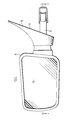
- an exterior rearview mirror comprises a base member 10, having a face 12 adapted to abut against a motor vehicle body panel, and a housing 14 in which a mirror glass 16 is mounted.
- the wall of the base member 10 opposite to the face 12 has a part-spherical portion 18 with a concave outer surface and a convex inner surface, with a circular opening 20 extending through the centre thereof.
- the concave outer surface of the wall portion 18 serves as a socket for a ball-and-socket joint, the ball of which is formed by a hollow spherical formation 22 on one end of a hollow cylindrical stem 24.
- the stem 24 extends through the hole 20 and projects beyond the face 12 of the base member 10 so as to extend into the interior of a vehicle on which the mirror is mounted.
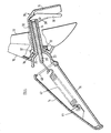
- An arm 26 has a first limb 28 which projects through the cylindrical stem 24 into the interior of the hollow hemispherical formation 22, and a second limb 30 which partially surrounds the stem 24 and carries a part-spherical concave formation 32 on its free end which engages with the convex inner surface of the wall portion 18.
- the arm 26 also has a lateral projection 34 with a release lever 36 mounted thereon by means of a pivot pin 38. One end of the lever 36 engages with the free end of the stem 24 while the other end can be manually squeezed against the projection 34 so as to cause displacement of the stem 24 relative to the arm 26.
- the housing 14 has an opening 40, the periphery of which is shaped to engage with the edge of the hemispherical formation 22.
- a tension spring 42 has one end attached to a formation 44 on the interior of the housing 14, and the other end attached to the free end of the first limb 28 of the lever 26.
- the effect of the tension spring 42 is to press the edge of the opening 40 into engagement with the edge of the hemispherical member 22, to press the hemispherical member 22 into engagement with the concave outer surface of the wall portion 18, to press the convex inner surface of the wall portion 18 into engagement with the formation 32 and to press the lever 36 into engagement with the stem 24.
- the housing 14 if the housing 14 is subject to impact from the front, it can pivot about the location at which the rear edge of the opening 14 engages with the rim of the hemispherical member 22, the rest of the edge of the opening 40 disengaging from the rim of the hemispherical member 22, as illustrated.
- the spring 42 pulls the housing 14 back into full engagement with the hemispherical member 22.
- the housing 14 can, of course, pivot in the opposite direction if it is subject to impact from the rear.
- the spring 42 serves both to hold the housing 14 in its preset orientation and to permit displacement thereof in the event of impact.
- Figure 5 illustrates an alternative embodiment of the invention in which the base member 10 and mirror housing 14 are identical with the corresponding components of the embodiment illustrated in Figures 1-4 and are denoted by the same reference numerals.
- a hollow hemispherical member 50 engages between the concave surface of the wall portion 18 and the edge of the opening 40 in the mirror housing 14 and has an attachment point 52 on its inner surface to which the spring 42 is attached.
- a first arm 54 has a flange 56 with a concave end face which engages with the convex inner surface of the wall portion 18.
- a second arm 58 is secured to the centre of the convex surface of the hemispherical member 52 and projects through the opening 20 in the wall portion 18.
- the second arm 54 has a lateral projection 60 on its free end.
- a lever 62 projects through an opening 64 in the first arm 54 and is pivotally attached by means of a pin 66 to the second arm 58 adjacent to the projection 56 thereof.
- a compression spring 68 engages between the flange 56 on the first arm 54 and a shoulder 70 on the second arm 58 so as to urge the flange 56 towards the hemispherical formation 50, squeezing the wall portion 18 therebetween. Squeezing the lever 62 against the projection 60 compresses the spring 68 and reduces the friction between the wall portion 18 and the surfaces of the flange 56 and hemispherical formation 50, thus permitting the orientation of the mirror head 14 to be adjusted.
- Figures 6 and 7 illustrate a further embodiment of the invention, having a base member 80 and housing 82 similar to the base member 10 and housing 14 of the previous embodiments, a mirror glass 84 being mounted in the housing 82.
- the base member 80 has a part-spherical wall portion 86 with a concave outer surface, a convex inner surface and a circular opening 88 extending through the centre thereof.
- the concave outer surface of the wall portion 86 serves as a socket for a ball-and-socket joint, the ball of which is formed by a part-spherical coupling member 88.
- the housing 14 has an opening 90, the periphery of which is shaped to engage with a circular rim 92 formed on the part-spherical member 88.
- the rim 92 bounds a cylindrical recess 94, across which extends a rod 96 to serve as an anchorage for one end of a tension spring 98, the other end of which is connected to an anchorage 100 on the interior of the housing 82.
- the spring 98 thus serves to bias the housing 82 in engagement with the part-spherical coupling member 88 while allowing it to be displaced in the event of impact, as with the previous embodiments.
- the recess 94 has a deepened central portion 102 of rectangular cross-section.
- a central bore 102 and two rectangular slots 106 and 108 extend through the coupling member 88 from the inner end of the recess 94 therein in alignment with the opening 88 in the part-spherical wall portion 86 of the base member 80.
- An actuating lever comprises a hollow cylindrical stem 110 with a concave part-spherical flange 112 on one end and a side arm 114 on the other.
- the concave flange 112 engages with the convex surface of the part-spherical wall portion 86 and has two projections 116 and 118 extending through the rectangular slots 106 and 108 and into the cylindrical part of the recess 90 where a circular disk 120 is secured to their free ends.
- a compression spring 122 located between the projections 116 and 118 has one end engaging with the disk 120 and the other end urging a second disk 124 into engagement with the bottom of the deepened portion 102 of the recess 90 between the slots 106 and 108.
- the tension spring 122 thus urges the hemispherical coupling member 88 into engagement with the concave surface of the wall portion 86 and the flange 112 into engagement with the convex portion thereof so as to tend to retain the housing in the orientation in which it is positioned.
- the stem 108 of the operating lever projects through a slot 126 in the base member 80 so that the handle 114 is accessible from within the vehicle.
- a release lever 128 extends parallel to the lever 114 and has a lug 126 at one end which engages in a notch in the side of the stem 108 to act as a fulcrum.
- the lever 128 has a protuberance 132 which extends into the central hole in the hollow stem 110 so as to engage with a pusher rod 134 accommodated therein. The other end of the pusher rod 134 engages with the disk 124.
- a compression spring 136 urges the two levers 114 and 128 apart, so as to bring protuberances 138 and 140 on their on their outer ends into abutment and thereby reduce any tendency for them to rattle.
- a flexible boot 142 extends between the base member 80 and the housing 82 so as to cover the joint therebetween.
Landscapes
- Engineering & Computer Science (AREA)
- Multimedia (AREA)
- Mechanical Engineering (AREA)
- Rear-View Mirror Devices That Are Mounted On The Exterior Of The Vehicle (AREA)
Applications Claiming Priority (2)
| Application Number | Priority Date | Filing Date | Title |
|---|---|---|---|
| GB8615065 | 1986-06-20 | ||
| GB868615065A GB8615065D0 (en) | 1986-06-20 | 1986-06-20 | Exterior rearview mirror |
Publications (1)
| Publication Number | Publication Date |
|---|---|
| EP0250177A1 true EP0250177A1 (de) | 1987-12-23 |
Family
ID=10599793
Family Applications (1)
| Application Number | Title | Priority Date | Filing Date |
|---|---|---|---|
| EP87305234A Withdrawn EP0250177A1 (de) | 1986-06-20 | 1987-06-12 | Aussenrückspiegel für Kraftfahrzeug |
Country Status (7)
| Country | Link |
|---|---|
| US (1) | US4755033A (de) |
| EP (1) | EP0250177A1 (de) |
| JP (1) | JPS632752A (de) |
| KR (1) | KR880000276A (de) |
| BR (1) | BR8703069A (de) |
| GB (1) | GB8615065D0 (de) |
| MY (1) | MY100664A (de) |
Cited By (1)
| Publication number | Priority date | Publication date | Assignee | Title |
|---|---|---|---|---|
| US20220274527A1 (en) * | 2018-05-04 | 2022-09-01 | Takie Adonis Stanger | Omni-directional self-orienting breakaway structures |
Families Citing this family (11)
| Publication number | Priority date | Publication date | Assignee | Title |
|---|---|---|---|---|
| AU597819B2 (en) * | 1987-05-04 | 1990-06-07 | Schefenacker Vision Systems Australia Pty Ltd | Breakaway mirror spring means |
| DE3718432C2 (de) * | 1987-06-02 | 1996-05-02 | Bernhard Mittelhaeuser | Aussenrückblickspiegel mit einem abklappbaren Gehäuse für Kraftfahrzeuge |
| US4934802A (en) * | 1988-02-25 | 1990-06-19 | Prince | Retractable conversation mirror |
| GB8810219D0 (en) * | 1988-04-29 | 1988-06-02 | Britax Geco Sa | Exterior mirror for motor vehicle |
| CA2015442C (en) * | 1990-04-25 | 1999-09-07 | Robert Coulthard | Safety marker suspension device |
| US20020073588A1 (en) * | 1990-06-11 | 2002-06-20 | Reynolds Randy B. | Point-of-purchase advertising by a cantilevered display mechanism and related methods |
| US5964443A (en) * | 1997-08-13 | 1999-10-12 | Cipa - Usa, Inc. | Mounting bracket system for a rearview mirror |
| US6024460A (en) * | 1998-07-10 | 2000-02-15 | Chrysler Corporation | Remote mirror adjustment mechanism |
| US6555222B1 (en) | 2000-01-13 | 2003-04-29 | Schefenacker Vision Systems France Sa | Reinforced polypropylene mirror assembly and process for making the same |
| US6910781B2 (en) * | 2002-06-26 | 2005-06-28 | Velvac, Inc. | Quick release vehicle mirror |
| CN107822303B (zh) * | 2017-08-11 | 2024-07-30 | 惠州进盈塑胶五金制品有限公司 | 一种新型摇头刷 |
Citations (4)
| Publication number | Priority date | Publication date | Assignee | Title |
|---|---|---|---|---|
| DE2431735A1 (de) * | 1974-07-02 | 1976-01-29 | Audi Nsu Auto Union Ag | Von innen einstellbarer aussenrueckspiegel |
| EP0020855A1 (de) * | 1979-03-23 | 1981-01-07 | Agfa-Gevaert AG | Verfahren und Vorrichtung zur Eichung eines Farbkopiergerätes |
| GB2116923A (en) * | 1982-03-19 | 1983-10-05 | Britax Geco Sa | Exterior rear-view mirror unit |
| EP0202855A2 (de) * | 1985-05-24 | 1986-11-26 | Britax Wingard Limited | Aussenrückblickspiegel |
Family Cites Families (5)
| Publication number | Priority date | Publication date | Assignee | Title |
|---|---|---|---|---|
| US3512746A (en) * | 1968-04-15 | 1970-05-19 | Mario Vitaloni | Adjustable side rear view mirror for motor vehicles |
| US3841769A (en) * | 1972-10-24 | 1974-10-15 | W Bowerman | Angularly adjustable bracket |
| US4523736A (en) * | 1982-03-02 | 1985-06-18 | Societe Manzoni-Bouchot | Device for mounting a rearview mirror casing on a support member |
| IT8453862U1 (it) * | 1984-09-27 | 1986-03-27 | Fiat Auto Spa | Specchio retrovisore esterno regolabile dall'interno per autoveicoli |
| US4620813A (en) * | 1984-10-09 | 1986-11-04 | Burroughs Corporation | Position retaining mechanism |
-
1986
- 1986-06-20 GB GB868615065A patent/GB8615065D0/en active Pending
-
1987
- 1987-06-12 EP EP87305234A patent/EP0250177A1/de not_active Withdrawn
- 1987-06-17 US US07/063,255 patent/US4755033A/en not_active Expired - Fee Related
- 1987-06-18 MY MYPI87000845A patent/MY100664A/en unknown
- 1987-06-18 BR BR8703069A patent/BR8703069A/pt unknown
- 1987-06-19 JP JP62153213A patent/JPS632752A/ja active Pending
- 1987-06-20 KR KR1019870006286A patent/KR880000276A/ko not_active Withdrawn
Patent Citations (4)
| Publication number | Priority date | Publication date | Assignee | Title |
|---|---|---|---|---|
| DE2431735A1 (de) * | 1974-07-02 | 1976-01-29 | Audi Nsu Auto Union Ag | Von innen einstellbarer aussenrueckspiegel |
| EP0020855A1 (de) * | 1979-03-23 | 1981-01-07 | Agfa-Gevaert AG | Verfahren und Vorrichtung zur Eichung eines Farbkopiergerätes |
| GB2116923A (en) * | 1982-03-19 | 1983-10-05 | Britax Geco Sa | Exterior rear-view mirror unit |
| EP0202855A2 (de) * | 1985-05-24 | 1986-11-26 | Britax Wingard Limited | Aussenrückblickspiegel |
Cited By (2)
| Publication number | Priority date | Publication date | Assignee | Title |
|---|---|---|---|---|
| US20220274527A1 (en) * | 2018-05-04 | 2022-09-01 | Takie Adonis Stanger | Omni-directional self-orienting breakaway structures |
| US11745661B2 (en) * | 2018-05-04 | 2023-09-05 | Takie Adonis Stanger | Omni-directional self-orienting breakaway structures |
Also Published As
| Publication number | Publication date |
|---|---|
| JPS632752A (ja) | 1988-01-07 |
| US4755033A (en) | 1988-07-05 |
| MY100664A (en) | 1991-01-17 |
| GB8615065D0 (en) | 1986-07-23 |
| BR8703069A (pt) | 1988-03-08 |
| KR880000276A (ko) | 1988-03-24 |
Similar Documents
| Publication | Publication Date | Title |
|---|---|---|
| US4755033A (en) | Exterior rearview mirror for a motor vehicle | |
| US4883349A (en) | Rear view mirror for motor vehicles | |
| US4400844A (en) | Wiper device | |
| US4475415A (en) | Outside door handle | |
| US4558840A (en) | Device for mounting a rearview mirror casing on a support member | |
| EP0290233B1 (de) | Federteile für einklappbaren Spiegel | |
| US4640142A (en) | Adjustable automobile mirror system | |
| US4053726A (en) | Push-button electrical switch | |
| US4687254A (en) | Belt lock arranged recessed in a pocket of a seat part | |
| US4735106A (en) | Brake operating device for bicycles | |
| EP1236616A1 (de) | Rückblickspiegelanordnung | |
| EP0074753B1 (de) | Rückspiegel für Kraftfahrzeuge | |
| EP0064815B1 (de) | Ferngesteuerter Rückblickspiegel | |
| EP0202855B1 (de) | Aussenrückblickspiegel | |
| EP0823571A2 (de) | Lenkradschalthebel für automatisches Getriebe | |
| JPH0129150Y2 (de) | ||
| JPH0134907Y2 (de) | ||
| US5432686A (en) | Handle control means for spotlights on automotive vehicles | |
| JPS6340649Y2 (de) | ||
| KR0180433B1 (ko) | 차량용 연료 주입구 도어 오픈 시스템 | |
| JP2648038B2 (ja) | 遭難信号自動発信器の起動スイッチ | |
| JPS6322886Y2 (de) | ||
| JPH04502Y2 (de) | ||
| JPS583238Y2 (ja) | レバ−スイツチのボ−ル保持機構 | |
| KR960004494Y1 (ko) | 차량용 윈도우 와이퍼 어댑터(Adaptor for connecting a wiper unit for Vehicle with the arm) |
Legal Events
| Date | Code | Title | Description |
|---|---|---|---|
| PUAI | Public reference made under article 153(3) epc to a published international application that has entered the european phase |
Free format text: ORIGINAL CODE: 0009012 |
|
| AK | Designated contracting states |
Kind code of ref document: A1 Designated state(s): DE ES FR GB IT |
|
| 17P | Request for examination filed |
Effective date: 19880229 |
|
| 17Q | First examination report despatched |
Effective date: 19890918 |
|
| STAA | Information on the status of an ep patent application or granted ep patent |
Free format text: STATUS: THE APPLICATION IS DEEMED TO BE WITHDRAWN |
|
| 18D | Application deemed to be withdrawn |
Effective date: 19900129 |
|
| RIN1 | Information on inventor provided before grant (corrected) |
Inventor name: BODDY, IAN Inventor name: WHITEHEAD, PETER JOHN |