EP0250545B1 - Optische datensammelanordnung und verfahren - Google Patents
Optische datensammelanordnung und verfahren Download PDFInfo
- Publication number
- EP0250545B1 EP0250545B1 EP87900462A EP87900462A EP0250545B1 EP 0250545 B1 EP0250545 B1 EP 0250545B1 EP 87900462 A EP87900462 A EP 87900462A EP 87900462 A EP87900462 A EP 87900462A EP 0250545 B1 EP0250545 B1 EP 0250545B1
- Authority
- EP
- European Patent Office
- Prior art keywords
- housing
- fluid
- radiant energy
- interface
- reflected
- Prior art date
- Legal status (The legal status is an assumption and is not a legal conclusion. Google has not performed a legal analysis and makes no representation as to the accuracy of the status listed.)
- Expired
Links
- 238000000034 method Methods 0.000 title claims description 8
- 230000003287 optical effect Effects 0.000 title abstract description 15
- 238000013480 data collection Methods 0.000 title 1
- 230000002457 bidirectional effect Effects 0.000 claims abstract description 4
- 239000012530 fluid Substances 0.000 claims description 17
- 230000005855 radiation Effects 0.000 claims description 10
- 230000004044 response Effects 0.000 abstract description 3
- 210000004369 blood Anatomy 0.000 description 16
- 239000008280 blood Substances 0.000 description 16
- 210000002381 plasma Anatomy 0.000 description 15
- 239000000306 component Substances 0.000 description 14
- 210000003743 erythrocyte Anatomy 0.000 description 13
- 230000003750 conditioning effect Effects 0.000 description 5
- 230000009977 dual effect Effects 0.000 description 5
- 238000000926 separation method Methods 0.000 description 4
- 238000010586 diagram Methods 0.000 description 3
- 239000007788 liquid Substances 0.000 description 3
- 230000007246 mechanism Effects 0.000 description 3
- 235000012771 pancakes Nutrition 0.000 description 3
- 230000001225 therapeutic effect Effects 0.000 description 3
- 238000001514 detection method Methods 0.000 description 2
- 230000000694 effects Effects 0.000 description 2
- 238000007743 anodising Methods 0.000 description 1
- 230000005540 biological transmission Effects 0.000 description 1
- 239000012503 blood component Substances 0.000 description 1
- 210000001772 blood platelet Anatomy 0.000 description 1
- 230000008859 change Effects 0.000 description 1
- 230000001143 conditioned effect Effects 0.000 description 1
- 238000006073 displacement reaction Methods 0.000 description 1
- 239000000835 fiber Substances 0.000 description 1
- 239000000463 material Substances 0.000 description 1
- 229920003023 plastic Polymers 0.000 description 1
- 238000005498 polishing Methods 0.000 description 1
- 230000011514 reflex Effects 0.000 description 1
- 239000007787 solid Substances 0.000 description 1
- 230000000007 visual effect Effects 0.000 description 1
Images




Classifications
-
- G—PHYSICS
- G01—MEASURING; TESTING
- G01P—MEASURING LINEAR OR ANGULAR SPEED, ACCELERATION, DECELERATION, OR SHOCK; INDICATING PRESENCE, ABSENCE, OR DIRECTION, OF MOVEMENT
- G01P3/00—Measuring linear or angular speed; Measuring differences of linear or angular speeds
- G01P3/42—Devices characterised by the use of electric or magnetic means
- G01P3/56—Devices characterised by the use of electric or magnetic means for comparing two speeds
- G01P3/60—Devices characterised by the use of electric or magnetic means for comparing two speeds by measuring or comparing frequency of generated currents or voltages
-
- G—PHYSICS
- G01—MEASURING; TESTING
- G01P—MEASURING LINEAR OR ANGULAR SPEED, ACCELERATION, DECELERATION, OR SHOCK; INDICATING PRESENCE, ABSENCE, OR DIRECTION, OF MOVEMENT
- G01P3/00—Measuring linear or angular speed; Measuring differences of linear or angular speeds
- G01P3/42—Devices characterised by the use of electric or magnetic means
- G01P3/44—Devices characterised by the use of electric or magnetic means for measuring angular speed
- G01P3/48—Devices characterised by the use of electric or magnetic means for measuring angular speed by measuring frequency of generated current or voltage
- G01P3/481—Devices characterised by the use of electric or magnetic means for measuring angular speed by measuring frequency of generated current or voltage of pulse signals
- G01P3/486—Devices characterised by the use of electric or magnetic means for measuring angular speed by measuring frequency of generated current or voltage of pulse signals delivered by photo-electric detectors
Definitions
- the invention pertains to non-contact systems, for collecting data off of a moving member and for bringing that data to a non-moving location. More particularly, the invention pertains to non-contact sensing systems usable with dual housing centrifuges wherein an outer housing is rotated at a first rotational velocity and an inner housing is rotated at a higher rotational velocity, usually twice that of the outer housing.
- processing of whole blood from a donor has come to routinely include separating the blood into therapeutic components. These components include red blood cells, platelets and plasma.
- Various techniques and apparatus have been developed to facilitate the collection of whole blood and the subsequent separation of therapeutic components therefrom.
- a second consideration in the processing of whole blood is the requirement that the processing take place under sterile conditions.
- a second consideration involves the requirement that unless the processing takes place within a single sealed system, the permitted storage duration and usable lifetime of the blood components is substantially shortened. Components processed within a sealed system can be stored for four to six weeks or longer before use. On the other hand, whole blood or components thereof must be used within 24 hours if the system seal is broken.
- One very common step in the processing of whole blood into various therapeutic components includes centrifuging the blood so as to bring about the desired separation of those components.
- the Adams patent discloses a centrifuge having an outer rotatable housing and an inner rotatable housing.
- the inner housing is positioned within and rotatably supported by the outer housing.
- the outer housing rotates at one rotational velocity, usually called one omega
- the inner rotatable housing rotates at twice the rotational velocity of the outer housing or two omega. There is thus a one omega difference in rotational speed of the two housings.
- the centrifuge of the Adams patent is particularly advantageous in that no seals are needed between moving and non-moving parts. Further, the system of the Adams patent, provides for the processing of blood into components in a single sealed system wherein whole blood from a donor can be infused into the centrifuge while the two housings of the centrifuge are being rotated.
- the system of the Adams patent uses a single motor coupled by gears and shafts to the two housings so as to provide the desired speed synchronization. This is an open loop system.
- centrifuge of the Adams patent provides an apparatus wherein blood processing may take place in a single sealed sterile system
- the mechanical apparatus of the Adams patent is subject to wear of the type normally experienced with gear driven systems.
- centrifuges in accordance with Adams disclosure must be built as precision mechanical systems. Since it is an open loop system, care must be exercised to insure that the two chambers do in fact continually operate at the desired speeds.
- the Lolachi mechanism as was the case with the Adams mechanism, is an open loop, essentially mechanical, structure for driving the two rotatable housings.
- United States Patent Nos. 3,986,442 and 4,113,173 illustrate alternate, open loop drive systems.
- Tachometer feedback is provided from the second motor through a set of slip rings or brushes for the purpose of continuously controlling the speed of the second motor with respect to the first moto.
- the structure of the Brown patent thus provides for obtaining electrical signals corresponding to the velocity of the inner motor for the purpose of continually controlling the speed thereof by means of a closed loop control system.
- United States Patent no. 4,109,855 to Brown et al. entitled “Drive System For Centrifugal Processing Apparatus” discloses yet another drive system.
- the system of the Brown et al. patent has an outer shaft, affixed to the outer housing for rotating the outer housing at a selected velocity.
- An inner shaft, coaxial with the outer shaft, is coupled to the inner housing.
- the inner shaft rotates the inner housing at twice the rotational velocity as the outer housing.
- the mechanism of the Brown et al. patent is an open loop system.
- the inner housing supports internally therein a spring biased mandrel which continually presses against a sealed, blood containing, container positioned within the inner housing.
- the system of this latter Brown patent also discloses the use of two separate electric motors to rotate the inner and outer housings. The motors are coupled to a control system.
- US-A-3679367 discloses a method of acquiring selected information from a moving member adapted to carry and to separate a selected fluid into at least two components, the method comprising rotating the member (26), separating the fluid into at least two components with an interface therebetween, generating a beam of radiant energy, directing the beam of radiant energy through the fluid at a selected region of the moving member adjacent the interface, and sensing at a fixed location the radiant energy passing through the fluid and generating an electrical signal related to the position of the interface in the region.
- the present invention is characterised by reflecting back at least a portion of the radiation received through the fluid from a reflecting position on the member so that the reflected radiation passes back through the fluid, and in that the reflected radiation is that sensed at said fixed location.
- the invention also provides apparatus whose characterising features correspond to those of the method.
- Figure 1 illustrates a centrifuge 10 with an outer rotary housing 12 which is mechanically coupled to an electric drive motor 14.
- the motor 14 can be a commercially available, pancake-type motor.
- the motor 14 has a stationary magnet 14a positioned adjacent a pancake armature 14b.
- the motor 14 rotates the housing 12 about an axis A-A.
- a hollow shaft 16 couples the armature 14b of the motor 14 to the rotary housing 12.
- the shaft 16 passes through a bearing structure 18 which provides rotary support for the housing 12.
- a stationary disk-shaped plate 19 is attached to the bearing structure 18 below the rotary housing 12.
- the rotary housing 12 has an upper portion 12a which is coupled to a lower portion 12b by a hinge 12c. As is illustrated in the above incorporated Brown patent, the upper portion 12a of the housing 12 can be rotated from a closed position, as illustrated in Figure 1 to an open position by rotation of the upper section 12a about the hinge 12c.
- Affixed to an upper member 20 of the housing section 12a is a second pancake-type electric motor 22.
- the motor 22 has a shaft 24 which rotates about an axis A′-A′.
- the axis A-A, A′-A′ as illustrated in Figure 1 coincide.
- Coincidence of the axis A-A, A′-A′ is not a requirement of the present invention. It would be within the spirit and scope of the present invention to space the axis A-A, A′-A′ apart from one another.
- Affixed to the shaft 24 is a second, inner, housing 26.
- the housing 26 is rotated within the housing 12 by the motor 22.
- a bearing structure 30 provides rotating support for the housing 26.
- the inner housing 26 is also formed of two separable sections.
- An upper section 26a as illustrated in Figure 1, is affixed to the shaft 24.
- a lower, removable section 26b is removably affixed to the upper section 26a by a flexible clamp 32.
- a spring loaded mandrel 34 is positioned within the housing 26.
- the mandrel 34 is downwardly biased, as illustrated in Figure 1, by a biasing spring 36.
- an optical system 40 In order to provide for dynamically determining the rotary velocity or the speed of rotation of the housing 26 while the housing 12 is being rotated, an optical system 40 is provided.
- the optical system 40 includes a source of radiant energy, such as an electric light, 42 which generates a beam of radiant energy which passes through a lens 44.
- the focused light beam 46 after exiting the lens 44, enters a beam splitter 48.
- the purpose of the beam splitter 48 is to direct a portion of the beam 46 upwardly along the axis A-A and into an end 50 of a fiber-optic radiant energy transmitting member 52.
- the fiber-optic member 52 functions as a bidirectional means for transmission of radiant energy.
- the fiber-optic member 52 is affixed to the hollow, rotating shaft 16 and centrally located with respect thereto along the axis of rotation A-A. As the shaft 16 rotates, and in turn rotates the housing 12, the fiber-optic member 52 also rotates.
- Radiant energy 46 which is deflected off of the beam splitter 48 into the lower end 50 of the fiber-optic member 52 is transmitted with essentially little or no losses to an upper end 56.
- the upper end 56 is positioned within the housing 12 adjacent a selectively reflecting member 58.
- the reflecting member 58 is affixed to a lower surface 60 of the housing member 26b.
- the selectively reflecting member 58 can be throught of as a data ring.
- Radiant ernergy which exits from the end 56 of the fiber-optic member 52 is directed toward the data ring 58.
- a mechanical support 62 positioned within the rotary housing 12 rigidly maintains the end 56 of the fiber-optic member 52 adjacent the data ring 58.
- Radiant energy which exits from the end 56 and which falls upon the data ring 58 is selectively reflected off the data ring 58 back into the end 56.
- the reflected radiant energy 64 passes through the fiber-optic member 52, exits the lower end 50 thereof, passes through the beam splitter 48 and impinges upon a photo detection unit 66.
- the photo detection unit 66 is electrically coupled via lines 68 to control system 70.
- the speed of rotation of the shaft 16 of the outer electric motor 14 may be sensed by affixing a tachometer disk 72 to an end of the shaft 16. As the disk 72 rotates, a second detector 74 can be used to sense its speed of rotation and generate electrical pulses proportion thereto on line 76.
- the rotational velocity of the housing 12 and the rotational velocity of the housing 26 may both be precisely controlled such that the housing 26 rotates at twice the velocity of the housing 12. Control is achieved by means of a closed loop system that does not utilize belts, gears and pullies as in many of the known prior art systems.
- Data ring 58 is illustrated in detail.
- Data ring 58 is formed of a plurality of spaced-apart reflective members 80 through 86.
- the members 80 through 86 are spaced apart and affixed to the lower surface 60 in a ring about the axis of rotation A′-A′.
- Between each of the reflective members 80 through 86 is a non-reflective or blackened region 90 through 96.
- the beam of radiant energy is illustrated in Figure 2 impinging upon a region of the data ring 58.
- the members 80 through 86 are preferably high reflective mirrors, they could also be formed on the surface 60 by polishing the surface 60 and darkening alternate regions thereof, for example by anodizing, so as to form the members 90 through 96.
- FIG. 3 illustrates schematically the control system 70.
- the control system 70 includes circuits 100 for conditioning the electrical pulses on the lines 68, corresponding to the relative rotational velocity of the housing 26 with respect to the housing 12.
- a second set of conditioning circuits 102 is coupled to the lines 76 to condition the electrical pulse train corresponding to the rotational velocity of the housing 12.
- the conditioning circuits 100 and 102 provide, respectively, inputs to comparison circuits 104 and 106.
- Set point inputs 108 and 110 specify predetermined, desired, rotational velocities for the motors 22 and 14, respectively.
- Error signals from the comparison circuits 104 and 106 are amplified in a set of motor control amplifiers 112 so as to provide outputs to the two motors.
- the control system 70 of Figure 3 will provide velocity error signals to the amplifiers 112 so as to maintain the rotational speed of the housing 26 at twice the rotational speed of the housing 12.
- the data ring 58 will not provide any information as to direction of rotation of the housing 26.
- control system 70 has been illustrated in block diagram form in Figure 3, it will be understood that the exact implementation thereof is not a limitation of the present invention.
- control system 70 could be implemented in hardwired form.
- a commercially available micro-processor could be used to implement the control system 70.
- control system of Figure 3 could be implemented as a proportional-integral-differential (PID) system.
- PID proportional-integral-differential
- FIG 4 illustrates an alternate embodiment of the system 10.
- the system 120 of Figure 4 includes the source of radiant energy 42 which generates visible white light, the beam splitter 48 which was present in the system 10 and two additional beam splitters 122 and 124.
- a color-coated filter such as a green filter 128 and a red filter 130.
- a corresponding optical detector 132 and 134 Associated with each of the respective filters 128 and 130 is a corresponding optical detector 132 and 134. Outputs from the detectors 132 and 134 are coupled via the lines 136 and 138 to a control system 140.
- the dual color detecting scheme of the system 120 operates in conjunction with a data ring 142 which is affixed to the lower surface 60 of the housing 26b.
- the detectors 132 and 134 are adapted to generate an electrical pulse train in response to sensing a beam of a selected frequency.
- the filters 128 and 130 selected sequences of green or red radiant energy pulses can be detected.
- the data ring 142 includes a plurality of spaced-apart, green reflective regions 150 through 154.
- the ring 142 includes a plurality of spaced-apart, red reflective regions 160 through 164.
- Green and red pulses of reflected radiant energy are transmitted back through the bidirectional member 52.
- the reflected green and red pulses pass through the respective green and red filters 128 and 130 and are detected by respective detectors 132 and 134.
- the sequence of detected red or green radiant energy pulses provides the same type of velocity information as is provided by the pulse train of the system 10 of Figure 1. Additionally, since two sets of spaced-apart pulse trains are generated on the lines 136 and 138, the direction of rotation of the housing 26 can also be determined.
- the data ring 142 can include reflective members 170 through 174 corresponding to the reflective members 80 through 84 of Figure 2.
- the reflective members of the data ring 142 are also spaced apart by a plurality of non-reflective members 180 through 184.
- the light beam reflected off of the mirrors 170 through 174 can be sensed by the redundancy detector 190 if desired.
- the motor control circuitry 140 of Figure 6 illustrates that portion of the control circuitry necessary to adjust the speed of the motor 22.
- the speed of the motor 14 is still adjusted using the circuitry previously discussed in Figure 3.
- Pulses from the green photo detector 132 and the red photo detector 134 are conditioned by circuits 200 and 202, respectively.
- Outputs from the conditioning circuits 200 and 202 are utilized by direction sensing circuitry 204 to generate a directional output on a line 206.
- a pulse train generated by the conditioning circuits 202 on lines 208 provides inputs to comparison circuitry 210.
- the pulse rate corresponding to the pulses from the red photo detector 134 is compared to a set point input 212.
- An error signal is then generated on lines 214.
- the error signal on the lines 214 is a velocity error signal which provides input to motor control circuitry 216.
- the motor control circuitry 216 in turn can be used to adjust the rotational velocity of the motor 22.
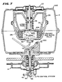
- Figure 7 illustrates yet another embodiment of the present invention. Elements of Figure 7 which correspond to elements of Figure 1 have again been given the same identification numerals.
- Figure 7 illustrates a system 220, usable as discussed in the above-incorporated Brown patent for the purpose of separating blood into red blood cell and plasma components. As is described in the above-incorporated Brown patent, after the container of whole blood has been positioned between the mandrel 34 and the lower part 26b of the housing 26, as the housing 26 is rotated, the blood will separate into packed red blood cells and plasma. The separation into components is illustrated schematically in Figure 7.
- An optical system of the general type used in system 10 transmits a beam of radiant energy to a data ring 222 which is affixed to the lower surface 60 of the housing portion 26b.
- the lower housing member 26b would preferably be formed of a transparent plastic material.
- the mandrel 34 has a highly-polished, mirrored surface, or a mirror 224 is affixed to a lower surface 226 generally above the data ring 222.
- the mirrored surface, or the mirror, 224 could be formed as a circular ring on the lower surface 226 of the mandrel 34.
- the interface between the plasma and the packed red blood cells is located between the data ring 222 and the reflecting surface or mirror 224. Radiant energy from the fiber-optic member 52 will pass through the-region of plasma to the mirrored surface 224 but will not pass through the packed red blood cells. Hence, provided the data ring 222 has a transparent region or regions, radiant energy from the end 56 of the fiber optic member 52 can be transmitted through the transparent region or regions of the data ring 222, and then through the plasma provided the interface is located as shown in Figure 7 to impinge upon the mirrored surface 224.
- the radiant energy that impinges on the mirrored surface 224 will be reflected back through the plasma, through the data ring 222 and back through the fiber-optic member 52 to the detector 66 where it will be converted to a usable electrical signal.
- the electrical signal corresponding to the liquid interface being positioned between the data ring 222 and the mirrored region 224 can be used to operate valves and/or visual indicators for purposes of operator control.
- Figure 8 illustrates the exemplary data ring 222.
- the data ring 222 can include a plurality of spaced-apart reflecting members such as the members 230 and 232.
- the members 230 and 232 correspond to the spaced-apart members 80 through 86 of Figure 2 and can be used to determine the rotational velocity of the housing 26.
- a longer mirrored region 240 can be provided for the purpose of generating a start or strobe signal to be used by the control system.
- a clear region 242 can be provided wherein the interface between the plasma and the red blood cells will appear and can be detected. The precise location of the interface between the plasma and the packed red blood cells, with respect to the clear region 282, will vary the amount of radiant energy or light reflected from the mirrored surface 224.
- the reflecting members and the clear member 242 can be spaced apart by a plurality of black or absorbing regions 250 through 256.
- the data ring 222 can be provided with additional clear regions such as the region 260.
- mirrored regions of various sizes such as the regions 262 and 264 can be provided to generate special control signals.
- the regions 262 and 264 can be spaced apart by non-reflective regions such as the region 266, which are substantially longer than the non-reflective regions 250 through 256.
- the data ring 222 could be provided with a plurality of spaced-apart red or green reflective regions as in the data ring 142 of Figure 5. In this configuration, in addition to sensing the presence or absence of the interface between the plasma and the red blood cells, the direction of rotation of the housing 26 can also be determined.
- a system 250 includes the dual, rotatably mounted housings 12 and 26.
- the exterior housing 12 is rotated by a pancake motor 252.
- the motor 252 includes a fixed ring magnet 252a and a rotatable pancake armature 252b.
- the armature 252b is mechanically affixed to a rotatable, hollow shaft 254 which rotates about an axis B-B.
- the shaft 254 is mechanically affixed to the lower portion 12b of the housing 12.
- a bearing assembly 256 rotatably supports the shaft 254.
- the motor 252 in Figure 9, is positioned above the bearing assembly 256.
- a seal 258 is positioned between the rotatable shaft 254 and the motor 252. While the bearing assembly 256 is located below the motor 252 in the system 250, as opposed to the arrangement of Figure 1 wherein the bearing assembly 18 is located above the motor 14, it will be understood that the exact arrangement of the bearing assembly with respect to the exterior motor is not a limitation of the present invention.
- a Dove prism 260 is positioned within the hollow shaft 254.
- the optical axis of the Dove prism 260 corresponds to the axis of rotation B-B of the shaft 254.
- the source of radiant energy 42 and focusing lens 44 generate the beam of radiant energy 46.
- the beam of radiant energy 46 is bent 90 degrees by the beam splitter 48 and directed along the axis B-B into the Dove prism 260.
- the beam 46 When the beam 46 exits the prism 260, it passes through a deflecting lens 262.
- the lens 262 deflects the beam 46 so that it is incident on a minor 264 which is affixed to.a lower surface 60 of the lower housing portion 26b.
- Radiant energy reflected off of the mirror 264 returns to the lens 262 and impinges upon the prism 260.
- the beam travels along essentially the same path, exiting at the lower end of the prism 260.
- the reflected beam then passes through the beam splitter 48, through a focusing lens 270, and impinges upon a quadrature detector 272.
- the image reflected onto the quadrature detector 272 causes that detector to generate electrical signals in response thereto.
- Those electrical signals generated by the quadrature detector 272 on lines 274 can be used as inputs to a control system or control circuitry 276.
- Movement of the image on the quadrature detector 272 will cause a change in the electrical signals on the lines 274 which can be sensed by the control circuitry 276.
- Output from the control circuitry 276 on the lines 278 can be communicated to the upper motor, corresponding to the motor 22 of Figure 1, via a set of slip rings 280 affixed to the rotatable shaft 254.
- Leads 282 located within the rotary housing 12 can be coupled to the upper motor 22 for the purpose of providing electrical control signals thereto.
- the control circuitry 276 can be the general type as illustrated in Figure 3. In this embodiment, the set point input on the lines 108 would correspond to a desired reflected image position on the quadrature detector 272. Alternately, the control system 276 could be implemented as the above-noted proportional-integral-differential control system.
- Figure 10 is a further illustration of the characteristics of the dove prism.
- the use of the dove prism 260 in the system 250 provides a solid state stroboscope which generates a stationary image on the quadrature detector 272 when the upper housing 26 is rotating at exactly twice the rotational velocity of the outer housing 12.
- Figure 10a depicts a Dove prism which is nothing more than a right angle prism with its point cut off.
- An object viewed through a Dove prism appears to be inverted in one axis but not the other - much like a mirror except that the mirroring effect is in line as opposed to reflex.
- Figure 10b illustrates the effect.
- An object arrow appears inverted when viewed through the Dove prism. If the object is rotated through some angle "A”, it appears to be rotated in the opposite direction when viewed through the prism as shown in Figure 10c. If the object remains stationary and the prism is rotated through some angle "A”, the object appears to rotate through an angle "2A” in the same direction as illustrated in Figure 10d. Finally, it has been observed and can be mathematically shown that if the object is rotated through an angle "2A” while the prism is rotated through an angle of just "A” as shown in Figure 10e, the object does not appear to rotate at all.
- a transmitter 290 indicated in phantom affixed to the top of the motor 22 of Figure 1 could be used to transmit velocity information to a fixed location.
- Velocity information concerning the speed of rotation of the housing 26 could be generated by affixing a tachometer disk 292, also shown in phantom, to the shaft 24.
- the location of the optical interface between the plasma and the packed red blood cells could be detected and transmitted to the fixed location.
- the transmitter 290 could be an infra-red or a radio-frequency transmitter.
- a stationary receiver, outside of the housing 12, could be used to detect the transmitted signals.
- the detected signals could be converted to electrical signals and supplied to a control system such as the control system 70.
- the exact form of the source of radiant energy 42 is not a limitation of the present invention.
- the source 42 could be an incandescent lamp.
- the beam of radiant energy 46 would be a beam of visible-light.
Landscapes
- Physics & Mathematics (AREA)
- General Physics & Mathematics (AREA)
- Centrifugal Separators (AREA)
- Reciprocating Pumps (AREA)
Claims (5)
Priority Applications (1)
| Application Number | Priority Date | Filing Date | Title |
|---|---|---|---|
| EP90200103A EP0377481B1 (de) | 1985-12-05 | 1986-12-03 | Drehzahlregelvorrichtung mit optischer Messwertgewinnung |
Applications Claiming Priority (2)
| Application Number | Priority Date | Filing Date | Title |
|---|---|---|---|
| US805512 | 1985-12-05 | ||
| US06/805,512 US4724317A (en) | 1985-12-05 | 1985-12-05 | Optical data collection apparatus and method used with moving members |
Related Child Applications (2)
| Application Number | Title | Priority Date | Filing Date |
|---|---|---|---|
| EP90200103A Division EP0377481B1 (de) | 1985-12-05 | 1986-12-03 | Drehzahlregelvorrichtung mit optischer Messwertgewinnung |
| EP90200103.1 Division-Into | 1990-01-16 |
Publications (3)
| Publication Number | Publication Date |
|---|---|
| EP0250545A1 EP0250545A1 (de) | 1988-01-07 |
| EP0250545A4 EP0250545A4 (de) | 1988-05-03 |
| EP0250545B1 true EP0250545B1 (de) | 1991-04-17 |
Family
ID=25191761
Family Applications (2)
| Application Number | Title | Priority Date | Filing Date |
|---|---|---|---|
| EP87900462A Expired EP0250545B1 (de) | 1985-12-05 | 1986-12-03 | Optische datensammelanordnung und verfahren |
| EP90200103A Expired - Lifetime EP0377481B1 (de) | 1985-12-05 | 1986-12-03 | Drehzahlregelvorrichtung mit optischer Messwertgewinnung |
Family Applications After (1)
| Application Number | Title | Priority Date | Filing Date |
|---|---|---|---|
| EP90200103A Expired - Lifetime EP0377481B1 (de) | 1985-12-05 | 1986-12-03 | Drehzahlregelvorrichtung mit optischer Messwertgewinnung |
Country Status (5)
| Country | Link |
|---|---|
| US (1) | US4724317A (de) |
| EP (2) | EP0250545B1 (de) |
| JP (1) | JPH0769334B2 (de) |
| DE (1) | DE3650075T2 (de) |
| WO (1) | WO1987003677A1 (de) |
Families Citing this family (87)
| Publication number | Priority date | Publication date | Assignee | Title |
|---|---|---|---|---|
| US5370802A (en) * | 1987-01-30 | 1994-12-06 | Baxter International Inc. | Enhanced yield platelet collection systems and methods |
| US4806252A (en) * | 1987-01-30 | 1989-02-21 | Baxter International Inc. | Plasma collection set and method |
| US5104526A (en) * | 1987-01-30 | 1992-04-14 | Baxter International Inc. | Centrifugation system having an interface detection system |
| US4834890A (en) * | 1987-01-30 | 1989-05-30 | Baxter International Inc. | Centrifugation pheresis system |
| US6780333B1 (en) | 1987-01-30 | 2004-08-24 | Baxter International Inc. | Centrifugation pheresis method |
| US5792372A (en) * | 1987-01-30 | 1998-08-11 | Baxter International, Inc. | Enhanced yield collection systems and methods for obtaining concentrated platelets from platelet-rich plasma |
| US5632893A (en) * | 1987-01-30 | 1997-05-27 | Baxter Internatinoal Inc. | Enhanced yield blood processing systems with angled interface control surface |
| US5076911A (en) * | 1987-01-30 | 1991-12-31 | Baxter International Inc. | Centrifugation chamber having an interface detection surface |
| US5573678A (en) * | 1987-01-30 | 1996-11-12 | Baxter International Inc. | Blood processing systems and methods for collecting mono nuclear cells |
| US4940543A (en) * | 1987-01-30 | 1990-07-10 | Baxter International Inc. | Plasma collection set |
| US5656163A (en) * | 1987-01-30 | 1997-08-12 | Baxter International Inc. | Chamber for use in a rotating field to separate blood components |
| US5628915A (en) * | 1987-01-30 | 1997-05-13 | Baxter International Inc. | Enhanced yield blood processing systems and methods establishing controlled vortex flow conditions |
| US5641414A (en) * | 1987-01-30 | 1997-06-24 | Baxter International Inc. | Blood processing systems and methods which restrict in flow of whole blood to increase platelet yields |
| DE3716464A1 (de) * | 1987-05-16 | 1988-12-08 | Danfoss As | Rotationsmaschine mit drehwinkel-messvorrichtung |
| US5168887A (en) * | 1990-05-18 | 1992-12-08 | Semitool, Inc. | Single wafer processor apparatus |
| DE3818594A1 (de) * | 1988-06-01 | 1989-12-07 | Hermle Kg Berthold | Zentrifuge |
| CH676786A5 (de) * | 1988-10-06 | 1991-03-15 | Lasag Ag | |
| US5316667A (en) * | 1989-05-26 | 1994-05-31 | Baxter International Inc. | Time based interface detection systems for blood processing apparatus |
| DE69026039T2 (de) * | 1989-12-08 | 1996-08-22 | Hitachi Koki Kk | System zum Festlegen der Betriebsbedingungen von Zentrifugenrotoren |
| US6375741B2 (en) * | 1991-03-06 | 2002-04-23 | Timothy J. Reardon | Semiconductor processing spray coating apparatus |
| DE4132965A1 (de) * | 1991-10-04 | 1993-04-08 | Fresenius Ag | Vorrichtung zur trennung von medien in deren bestandteile |
| CA2103914A1 (en) * | 1991-12-23 | 1993-06-24 | Warren P. Williamson, Iv | Centrifugal processing system with direct access drawer |
| US6007725A (en) | 1991-12-23 | 1999-12-28 | Baxter International Inc. | Systems and methods for on line collection of cellular blood components that assure donor comfort |
| US5549834A (en) | 1991-12-23 | 1996-08-27 | Baxter International Inc. | Systems and methods for reducing the number of leukocytes in cellular products like platelets harvested for therapeutic purposes |
| EP0572656B1 (de) * | 1991-12-23 | 1997-11-05 | Baxter International Inc. | Zentrifuge wobei korb und spule trennbar sind zum verschaffen von zugang zur trennkammer |
| US5804079A (en) | 1991-12-23 | 1998-09-08 | Baxter International Inc. | Systems and methods for reducing the number of leukocytes in cellular products like platelets harvested for therapeutic purposes |
| US5282981A (en) * | 1992-05-01 | 1994-02-01 | E. I. Du Pont De Nemours And Company | Flow restrictor-separation device |
| US5271852A (en) * | 1992-05-01 | 1993-12-21 | E. I. Du Pont De Nemours And Company | Centrifugal methods using a phase-separation tube |
| WO1994008689A1 (en) * | 1992-10-22 | 1994-04-28 | Baxter International Inc. | Blood processing systems with improved data transfer between stationary and rotating elements |
| JP3146285B2 (ja) | 1992-10-22 | 2001-03-12 | バクスター、インターナショナル、インコーポレイテッド | 血液処理装置のための時間準拠界面検出システム |
| US5427695A (en) * | 1993-07-26 | 1995-06-27 | Baxter International Inc. | Systems and methods for on line collecting and resuspending cellular-rich blood products like platelet concentrate |
| US5525218A (en) * | 1993-10-29 | 1996-06-11 | Baxter International Inc. | Centrifuge with separable bowl and spool elements providing access to the separation chamber |
| DE9401758U1 (de) * | 1994-02-03 | 1994-03-17 | Sigma Laborzentrifugen Gmbh, 37520 Osterode | Zentrifuge |
| US5961842A (en) * | 1995-06-07 | 1999-10-05 | Baxter International Inc. | Systems and methods for collecting mononuclear cells employing control of packed red blood cell hematocrit |
| US5980760A (en) * | 1997-07-01 | 1999-11-09 | Baxter International Inc. | System and methods for harvesting mononuclear cells by recirculation of packed red blood cells |
| US6027441A (en) * | 1997-07-01 | 2000-02-22 | Baxter International Inc. | Systems and methods providing a liquid-primed, single flow access chamber |
| US6027657A (en) * | 1997-07-01 | 2000-02-22 | Baxter International Inc. | Systems and methods for collecting diluted mononuclear cells |
| US20040166593A1 (en) * | 2001-06-22 | 2004-08-26 | Nolte David D. | Adaptive interferometric multi-analyte high-speed biosensor |
| US7186230B2 (en) * | 2002-03-04 | 2007-03-06 | Therakos, Inc | Method and apparatus for the continuous separation of biological fluids into components |
| US7479123B2 (en) | 2002-03-04 | 2009-01-20 | Therakos, Inc. | Method for collecting a desired blood component and performing a photopheresis treatment |
| US7211037B2 (en) * | 2002-03-04 | 2007-05-01 | Therakos, Inc. | Apparatus for the continuous separation of biological fluids into components and method of using same |
| US20040127840A1 (en) * | 2002-03-04 | 2004-07-01 | Steve Gara | Blood separation apparatus and method of using the same |
| US20030205538A1 (en) | 2002-05-03 | 2003-11-06 | Randel Dorian | Methods and apparatus for isolating platelets from blood |
| US7832566B2 (en) | 2002-05-24 | 2010-11-16 | Biomet Biologics, Llc | Method and apparatus for separating and concentrating a component from a multi-component material including macroparticles |
| US7845499B2 (en) | 2002-05-24 | 2010-12-07 | Biomet Biologics, Llc | Apparatus and method for separating and concentrating fluids containing multiple components |
| US20060278588A1 (en) | 2002-05-24 | 2006-12-14 | Woodell-May Jennifer E | Apparatus and method for separating and concentrating fluids containing multiple components |
| DE10240451A1 (de) * | 2002-09-02 | 2004-03-11 | Dürr Systems GmbH | Sensoranordnung für eine Beschichtungsanlage |
| US7327443B2 (en) * | 2004-07-01 | 2008-02-05 | Gambro Bct, Inc | Stroboscopic LED light source for blood processing apparatus |
| CN103454191B (zh) * | 2003-07-02 | 2016-01-06 | 泰尔茂比司特公司 | 用于利用预测数据分析算法控制血液处理离心机的方法 |
| ITMI20031715A1 (it) * | 2003-09-05 | 2005-03-06 | Dideco Spa | Dispositivo di comando nella raccolta differenziata dei |
| US7060018B2 (en) * | 2003-09-11 | 2006-06-13 | Cobe Cardiovascular, Inc. | Centrifuge apparatus for processing blood |
| US7671975B2 (en) * | 2004-07-01 | 2010-03-02 | Caridianbct, Inc. | Blood processing apparatus with dedicated stroboscopic controller for LED source |
| EP1848472B1 (de) * | 2005-02-07 | 2015-04-01 | Hanuman LLC | Vorrichtung und verfahren für ein blutplättchenreiches plasmakonzentrat |
| US7708152B2 (en) * | 2005-02-07 | 2010-05-04 | Hanuman Llc | Method and apparatus for preparing platelet rich plasma and concentrates thereof |
| US7866485B2 (en) | 2005-02-07 | 2011-01-11 | Hanuman, Llc | Apparatus and method for preparing platelet rich plasma and concentrates thereof |
| US8567609B2 (en) | 2006-05-25 | 2013-10-29 | Biomet Biologics, Llc | Apparatus and method for separating and concentrating fluids containing multiple components |
| CN101501472A (zh) | 2006-08-17 | 2009-08-05 | 科安比司特公司 | 具有鲁棒性自动处理控制的血液处理设备 |
| US20080041772A1 (en) * | 2006-08-17 | 2008-02-21 | Gambro Bct, Inc. | Blood Processing Apparatus with Robust Outflow Process Control |
| JP2009294236A (ja) * | 2006-09-28 | 2009-12-17 | Mitsubishi Electric Corp | アレイ型光学部品およびその製造方法、ならびにアレイ型半導体レーザ用光学系 |
| EP2146794B1 (de) | 2007-04-12 | 2016-10-19 | Biomet Biologics, LLC | Fraktionierungssystem für suspensionen mit trennungsschwimmer |
| US8328024B2 (en) | 2007-04-12 | 2012-12-11 | Hanuman, Llc | Buoy suspension fractionation system |
| EP2220477B1 (de) * | 2007-12-18 | 2011-09-21 | CaridianBCT, Inc. | Blutbehandlungsvorrichtung mit einem versiegelten diffusor in einer vorrichtung zur optischen steuerung |
| WO2009085350A1 (en) * | 2007-12-27 | 2009-07-09 | Caridianbct, Inc. | Blood processing apparatus with controlled cell capture chamber trigger |
| EP2620139B1 (de) | 2008-02-27 | 2016-07-20 | Biomet Biologics, LLC | Interleukin-1-Rezeptorantagonisten-reiche Lösungen |
| US8337711B2 (en) * | 2008-02-29 | 2012-12-25 | Biomet Biologics, Llc | System and process for separating a material |
| US8012077B2 (en) * | 2008-05-23 | 2011-09-06 | Biomet Biologics, Llc | Blood separating device |
| US7951059B2 (en) * | 2008-09-18 | 2011-05-31 | Caridianbct, Inc. | Blood processing apparatus with optical reference control |
| US20100131232A1 (en) * | 2008-11-21 | 2010-05-27 | Taylor Timothy M | Belt slip meter |
| EP2361376B1 (de) * | 2008-12-22 | 2020-09-23 | Terumo BCT, Inc. | Blutprozessor mit digital kontrolliertem linearem spannungsregulator für optische pulse |
| US8187475B2 (en) | 2009-03-06 | 2012-05-29 | Biomet Biologics, Llc | Method and apparatus for producing autologous thrombin |
| US8313954B2 (en) | 2009-04-03 | 2012-11-20 | Biomet Biologics, Llc | All-in-one means of separating blood components |
| US9011800B2 (en) * | 2009-07-16 | 2015-04-21 | Biomet Biologics, Llc | Method and apparatus for separating biological materials |
| EP2644216B1 (de) | 2009-12-11 | 2016-04-06 | Terumo BCT, Inc. | System zur Bluttrennung mit abgeschirmtem Extraktionsport und optischer Steuerung |
| US8591391B2 (en) | 2010-04-12 | 2013-11-26 | Biomet Biologics, Llc | Method and apparatus for separating a material |
| US9642956B2 (en) | 2012-08-27 | 2017-05-09 | Biomet Biologics, Llc | Apparatus and method for separating and concentrating fluids containing multiple components |
| WO2014127122A1 (en) | 2013-02-18 | 2014-08-21 | Terumo Bct, Inc. | System for blood separation with a separation chamber having an internal gravity valve |
| US20140271589A1 (en) | 2013-03-15 | 2014-09-18 | Biomet Biologics, Llc | Treatment of collagen defects using protein solutions |
| US9895418B2 (en) | 2013-03-15 | 2018-02-20 | Biomet Biologics, Llc | Treatment of peripheral vascular disease using protein solutions |
| US10143725B2 (en) | 2013-03-15 | 2018-12-04 | Biomet Biologics, Llc | Treatment of pain using protein solutions |
| US10208095B2 (en) | 2013-03-15 | 2019-02-19 | Biomet Manufacturing, Llc | Methods for making cytokine compositions from tissues using non-centrifugal methods |
| US9950035B2 (en) | 2013-03-15 | 2018-04-24 | Biomet Biologics, Llc | Methods and non-immunogenic compositions for treating inflammatory disorders |
| US10166322B2 (en) | 2014-03-28 | 2019-01-01 | Terumo Bct, Inc. | Gain in separation processes with control loop |
| EP3073274A1 (de) | 2015-03-27 | 2016-09-28 | Alfa Laval Corporate AB | System zur detektion von rotation |
| US9713810B2 (en) | 2015-03-30 | 2017-07-25 | Biomet Biologics, Llc | Cell washing plunger using centrifugal force |
| US9757721B2 (en) | 2015-05-11 | 2017-09-12 | Biomet Biologics, Llc | Cell washing plunger using centrifugal force |
| ES3041510T3 (en) | 2017-04-21 | 2025-11-12 | Terumo Bct Inc | System for high-throughput blood component collection |
| US12564668B2 (en) | 2022-08-02 | 2026-03-03 | Terumo Bct, Inc. | Methods and systems for high-throughput blood component collection |
Family Cites Families (13)
| Publication number | Priority date | Publication date | Assignee | Title |
|---|---|---|---|---|
| US2454959A (en) * | 1946-02-18 | 1948-11-30 | Gen Electric | Optical apparatus for showing rotating parts at rest |
| US3471236A (en) * | 1964-03-30 | 1969-10-07 | Us Army | Prism for optical stroboscope |
| GB1325536A (en) * | 1969-08-13 | 1973-08-01 | Mse Holdings Ltd | Centrifuges |
| US3679367A (en) * | 1970-09-14 | 1972-07-25 | Technicon Instr | Apparatus for determining the pack volume of particulates in liquid mixtures |
| DE2720711C2 (de) * | 1977-05-07 | 1986-10-09 | Linde Ag, 6200 Wiesbaden | Axialkolbenmaschine |
| US4162399A (en) * | 1977-09-16 | 1979-07-24 | Bei Electronics, Inc. | Optical encoder with fiber optics |
| US4205261A (en) * | 1978-07-13 | 1980-05-27 | Beckman Instruments, Inc. | Ultracentrifuge overspeed disk detection system |
| US4387299A (en) * | 1979-06-25 | 1983-06-07 | Yazaki Sogyo Kabushiki Kaisha | Travel-distance signal generator for vehicles |
| DE3018496A1 (de) * | 1980-05-14 | 1981-11-19 | Walter Dipl.-Ing. Dr.-Ing. 8012 Ottobrunn Mehnert | Verfahren und vorrichtung zur messung eines winkels |
| JPS59151014A (ja) * | 1982-12-10 | 1984-08-29 | フオ−ド・エアロスペイス・アンド・コミユニケイシヨンズ・コ−ポレイシヨン | ジヤイロスコ−プ式取付けロ−タ用オプチカルフアイバ回転センサ |
| DE3247174A1 (de) * | 1982-12-21 | 1984-06-28 | Standard Elektrik Lorenz Ag, 7000 Stuttgart | Bewegungsrichtungsgeber |
| US4507110A (en) * | 1983-10-20 | 1985-03-26 | E. I. Du Pont De Nemours And Company | Adjustable photosensor mounting arrangement for a centrifuge |
| US4530691A (en) * | 1983-12-13 | 1985-07-23 | Baxter Travenol Laboratories, Inc. | Centrifuge with movable mandrel |
-
1985
- 1985-12-05 US US06/805,512 patent/US4724317A/en not_active Expired - Lifetime
-
1986
- 1986-12-03 JP JP62500255A patent/JPH0769334B2/ja not_active Expired - Lifetime
- 1986-12-03 EP EP87900462A patent/EP0250545B1/de not_active Expired
- 1986-12-03 EP EP90200103A patent/EP0377481B1/de not_active Expired - Lifetime
- 1986-12-03 DE DE3650075T patent/DE3650075T2/de not_active Expired - Fee Related
- 1986-12-03 WO PCT/US1986/002602 patent/WO1987003677A1/en not_active Ceased
Also Published As
| Publication number | Publication date |
|---|---|
| DE3650075D1 (de) | 1994-10-27 |
| US4724317A (en) | 1988-02-09 |
| EP0250545A1 (de) | 1988-01-07 |
| EP0377481B1 (de) | 1994-09-21 |
| DE3650075T2 (de) | 1995-05-18 |
| WO1987003677A1 (en) | 1987-06-18 |
| JPS63502451A (ja) | 1988-09-14 |
| EP0377481A2 (de) | 1990-07-11 |
| JPH0769334B2 (ja) | 1995-07-26 |
| EP0250545A4 (de) | 1988-05-03 |
| EP0377481A3 (de) | 1992-01-15 |
Similar Documents
| Publication | Publication Date | Title |
|---|---|---|
| US4724317A (en) | Optical data collection apparatus and method used with moving members | |
| CN106377813B (zh) | 用于血液处理系统的界面检测器 | |
| US3864030A (en) | Eye position measuring technique | |
| US4259584A (en) | Apparatus for transmitting signals | |
| US3982162A (en) | Centrifuges | |
| US4266862A (en) | Refractometer for the automatic objective determination of the refractive condition of an eye | |
| US3642233A (en) | System for the optical automatic and autonomous guiding of self-rotating missiles | |
| JPS59192959A (ja) | 血液をその成分に分離する方法および分離する装置 | |
| US4205261A (en) | Ultracentrifuge overspeed disk detection system | |
| SE454626B (sv) | Optiskt avsokningssystem | |
| EP0457083B1 (de) | Beschleunigungsmesser | |
| US4538062A (en) | Focusing detecting device with coaxial source and detector | |
| US4328421A (en) | Horizon sensor | |
| JPH029291B2 (de) | ||
| US4332470A (en) | Spectrophotometer system having power line synchronization | |
| JPH10225159A (ja) | 出力軸の回転数を制御するための方法および装置 | |
| US6373073B1 (en) | Multiple spectral band opto-mechanical modular | |
| US4848903A (en) | Method and apparatus for measuring the optical axis of a guide beam projector | |
| US4609817A (en) | Optical shaft position sensor | |
| US3521071A (en) | Electro-optical apparatus for developing an effect representative of the attitude of the apparatus relative to that of a source of radiant energy | |
| US4842247A (en) | Method and apparatus for the detection of helicopters | |
| US4619505A (en) | Refractometry process and device for measuring the degree of ametropia, and especially the degree of astigmatism, of the eye | |
| CN118275360A (zh) | 一种微流控光学检测装置和光学检测系统 | |
| SU1188596A1 (ru) | Устройство дл контрол момента трени подшипников электроприводов | |
| EP4245331B1 (de) | Zentrifuge mit kontaktloser energiequelle für eine elektronische aktive vorrichtung |
Legal Events
| Date | Code | Title | Description |
|---|---|---|---|
| PUAI | Public reference made under article 153(3) epc to a published international application that has entered the european phase |
Free format text: ORIGINAL CODE: 0009012 |
|
| 17P | Request for examination filed |
Effective date: 19870819 |
|
| AK | Designated contracting states |
Kind code of ref document: A1 Designated state(s): DE FR GB IT |
|
| A4 | Supplementary search report drawn up and despatched |
Effective date: 19880503 |
|
| RAP1 | Party data changed (applicant data changed or rights of an application transferred) |
Owner name: BAXTER INTERNATIONAL INC. |
|
| 17Q | First examination report despatched |
Effective date: 19890728 |
|
| GRAA | (expected) grant |
Free format text: ORIGINAL CODE: 0009210 |
|
| AK | Designated contracting states |
Kind code of ref document: B1 Designated state(s): DE FR GB IT |
|
| XX | Miscellaneous (additional remarks) |
Free format text: TEILANMELDUNG 90200103.1 EINGEREICHT AM 03/12/86. |
|
| ITF | It: translation for a ep patent filed | ||
| REF | Corresponds to: |
Ref document number: 3678834 Country of ref document: DE Date of ref document: 19910523 |
|
| ET | Fr: translation filed | ||
| PLBE | No opposition filed within time limit |
Free format text: ORIGINAL CODE: 0009261 |
|
| STAA | Information on the status of an ep patent application or granted ep patent |
Free format text: STATUS: NO OPPOSITION FILED WITHIN TIME LIMIT |
|
| 26N | No opposition filed | ||
| PGFP | Annual fee paid to national office [announced via postgrant information from national office to epo] |
Ref country code: DE Payment date: 20001116 Year of fee payment: 15 |
|
| PGFP | Annual fee paid to national office [announced via postgrant information from national office to epo] |
Ref country code: FR Payment date: 20001117 Year of fee payment: 15 |
|
| PGFP | Annual fee paid to national office [announced via postgrant information from national office to epo] |
Ref country code: GB Payment date: 20001121 Year of fee payment: 15 |
|
| PG25 | Lapsed in a contracting state [announced via postgrant information from national office to epo] |
Ref country code: GB Free format text: LAPSE BECAUSE OF NON-PAYMENT OF DUE FEES Effective date: 20011203 |
|
| REG | Reference to a national code |
Ref country code: GB Ref legal event code: IF02 |
|
| PG25 | Lapsed in a contracting state [announced via postgrant information from national office to epo] |
Ref country code: DE Free format text: LAPSE BECAUSE OF NON-PAYMENT OF DUE FEES Effective date: 20020702 |
|
| GBPC | Gb: european patent ceased through non-payment of renewal fee |
Effective date: 20011203 |
|
| PG25 | Lapsed in a contracting state [announced via postgrant information from national office to epo] |
Ref country code: FR Free format text: LAPSE BECAUSE OF NON-PAYMENT OF DUE FEES Effective date: 20020830 |
|
| REG | Reference to a national code |
Ref country code: FR Ref legal event code: ST |
|
| PG25 | Lapsed in a contracting state [announced via postgrant information from national office to epo] |
Ref country code: IT Free format text: LAPSE BECAUSE OF NON-PAYMENT OF DUE FEES Effective date: 20051203 |