EP0250622A1 - Procédé de traitement de nourriture liquide - Google Patents
Procédé de traitement de nourriture liquide Download PDFInfo
- Publication number
- EP0250622A1 EP0250622A1 EP86108769A EP86108769A EP0250622A1 EP 0250622 A1 EP0250622 A1 EP 0250622A1 EP 86108769 A EP86108769 A EP 86108769A EP 86108769 A EP86108769 A EP 86108769A EP 0250622 A1 EP0250622 A1 EP 0250622A1
- Authority
- EP
- European Patent Office
- Prior art keywords
- processor
- rotator
- treatment zone
- zone
- rpm
- Prior art date
- Legal status (The legal status is an assumption and is not a legal conclusion. Google has not performed a legal analysis and makes no representation as to the accuracy of the status listed.)
- Granted
Links
- 239000012530 fluid Substances 0.000 title claims abstract description 33
- 235000013305 food Nutrition 0.000 title claims abstract description 24
- 238000000034 method Methods 0.000 title description 4
- 230000008569 process Effects 0.000 title description 4
- 238000011282 treatment Methods 0.000 claims abstract description 70
- 238000012545 processing Methods 0.000 claims abstract description 36
- 238000012546 transfer Methods 0.000 claims abstract description 13
- 239000000463 material Substances 0.000 claims description 32
- 239000000758 substrate Substances 0.000 claims description 27
- 238000010943 off-gassing Methods 0.000 claims description 5
- 230000015572 biosynthetic process Effects 0.000 claims description 4
- 229920000642 polymer Polymers 0.000 claims description 2
- 239000004215 Carbon black (E152) Substances 0.000 claims 1
- 229930195733 hydrocarbon Natural products 0.000 claims 1
- 150000002430 hydrocarbons Chemical class 0.000 claims 1
- 239000000047 product Substances 0.000 description 43
- 239000000306 component Substances 0.000 description 8
- 230000000694 effects Effects 0.000 description 7
- 238000010438 heat treatment Methods 0.000 description 4
- 238000001816 cooling Methods 0.000 description 3
- 230000008878 coupling Effects 0.000 description 3
- 238000010168 coupling process Methods 0.000 description 3
- 238000005859 coupling reaction Methods 0.000 description 3
- 239000002245 particle Substances 0.000 description 3
- -1 polyethylene Polymers 0.000 description 3
- 239000000084 colloidal system Substances 0.000 description 2
- 238000013461 design Methods 0.000 description 2
- 239000000839 emulsion Substances 0.000 description 2
- 239000000543 intermediate Substances 0.000 description 2
- 238000004806 packaging method and process Methods 0.000 description 2
- 102000004169 proteins and genes Human genes 0.000 description 2
- 108090000623 proteins and genes Proteins 0.000 description 2
- 238000012552 review Methods 0.000 description 2
- 229910001220 stainless steel Inorganic materials 0.000 description 2
- 239000010935 stainless steel Substances 0.000 description 2
- 238000003860 storage Methods 0.000 description 2
- 241000196324 Embryophyta Species 0.000 description 1
- 208000035126 Facies Diseases 0.000 description 1
- 241000277275 Oncorhynchus mykiss Species 0.000 description 1
- 239000004698 Polyethylene Substances 0.000 description 1
- 241000219094 Vitaceae Species 0.000 description 1
- 239000005862 Whey Substances 0.000 description 1
- 102000007544 Whey Proteins Human genes 0.000 description 1
- 108010046377 Whey Proteins Proteins 0.000 description 1
- 238000005054 agglomeration Methods 0.000 description 1
- 230000002776 aggregation Effects 0.000 description 1
- 230000004888 barrier function Effects 0.000 description 1
- 239000012267 brine Substances 0.000 description 1
- 230000008859 change Effects 0.000 description 1
- UUAGAQFQZIEFAH-UHFFFAOYSA-N chlorotrifluoroethylene Chemical group FC(F)=C(F)Cl UUAGAQFQZIEFAH-UHFFFAOYSA-N 0.000 description 1
- 239000011248 coating agent Substances 0.000 description 1
- 238000000576 coating method Methods 0.000 description 1
- 230000003247 decreasing effect Effects 0.000 description 1
- 230000002939 deleterious effect Effects 0.000 description 1
- 230000001627 detrimental effect Effects 0.000 description 1
- 238000009826 distribution Methods 0.000 description 1
- 230000001804 emulsifying effect Effects 0.000 description 1
- 239000011552 falling film Substances 0.000 description 1
- 239000010419 fine particle Substances 0.000 description 1
- 239000005428 food component Substances 0.000 description 1
- 235000012041 food component Nutrition 0.000 description 1
- 235000021021 grapes Nutrition 0.000 description 1
- 238000003754 machining Methods 0.000 description 1
- 238000004519 manufacturing process Methods 0.000 description 1
- 238000012544 monitoring process Methods 0.000 description 1
- 238000000465 moulding Methods 0.000 description 1
- 230000036961 partial effect Effects 0.000 description 1
- 229920000573 polyethylene Polymers 0.000 description 1
- 229920001343 polytetrafluoroethylene Polymers 0.000 description 1
- 239000004810 polytetrafluoroethylene Substances 0.000 description 1
- 230000002035 prolonged effect Effects 0.000 description 1
- 238000003303 reheating Methods 0.000 description 1
- 235000014438 salad dressings Nutrition 0.000 description 1
- 238000000926 separation method Methods 0.000 description 1
- 238000010008 shearing Methods 0.000 description 1
- 239000002002 slurry Substances 0.000 description 1
- HPALAKNZSZLMCH-UHFFFAOYSA-M sodium;chloride;hydrate Chemical compound O.[Na+].[Cl-] HPALAKNZSZLMCH-UHFFFAOYSA-M 0.000 description 1
- 239000000243 solution Substances 0.000 description 1
- 230000001052 transient effect Effects 0.000 description 1
- 238000011144 upstream manufacturing Methods 0.000 description 1
- XLYOFNOQVPJJNP-UHFFFAOYSA-N water Substances O XLYOFNOQVPJJNP-UHFFFAOYSA-N 0.000 description 1
Images


Classifications
-
- B—PERFORMING OPERATIONS; TRANSPORTING
- B01—PHYSICAL OR CHEMICAL PROCESSES OR APPARATUS IN GENERAL
- B01F—MIXING, e.g. DISSOLVING, EMULSIFYING OR DISPERSING
- B01F27/00—Mixers with rotary stirring devices in fixed receptacles; Kneaders
- B01F27/27—Mixers with stator-rotor systems, e.g. with intermeshing teeth or cylinders or having orifices
- B01F27/272—Mixers with stator-rotor systems, e.g. with intermeshing teeth or cylinders or having orifices with means for moving the materials to be mixed axially between the surfaces of the rotor and the stator, e.g. the stator rotor system formed by conical or cylindrical surfaces
-
- B—PERFORMING OPERATIONS; TRANSPORTING
- B01—PHYSICAL OR CHEMICAL PROCESSES OR APPARATUS IN GENERAL
- B01F—MIXING, e.g. DISSOLVING, EMULSIFYING OR DISPERSING
- B01F25/00—Flow mixers; Mixers for falling materials, e.g. solid particles
- B01F2025/91—Direction of flow or arrangement of feed and discharge openings
-
- B—PERFORMING OPERATIONS; TRANSPORTING
- B01—PHYSICAL OR CHEMICAL PROCESSES OR APPARATUS IN GENERAL
- B01F—MIXING, e.g. DISSOLVING, EMULSIFYING OR DISPERSING
- B01F25/00—Flow mixers; Mixers for falling materials, e.g. solid particles
- B01F2025/91—Direction of flow or arrangement of feed and discharge openings
- B01F2025/911—Axial flow
-
- B—PERFORMING OPERATIONS; TRANSPORTING
- B01—PHYSICAL OR CHEMICAL PROCESSES OR APPARATUS IN GENERAL
- B01F—MIXING, e.g. DISSOLVING, EMULSIFYING OR DISPERSING
- B01F27/00—Mixers with rotary stirring devices in fixed receptacles; Kneaders
- B01F27/80—Mixers with rotary stirring devices in fixed receptacles; Kneaders with stirrers rotating about a substantially vertical axis
Definitions
- the present invention relates to the processing of food and, in particular, a device for processing fluid foods.
- the food industry utilizes a large variety of treatments in the production of the many and diverse food products now avilable. Such treatments process food into the different forms and type of food products expected by the present-day consumer and also convert food into non-perishable forms, the latter requirement being well appreciated as highly desirable even by primitive man. As far as fluid foods are concerned, widely used treatments include simple mixing; emulsifying; homogenizing; comminuting; heating/cooling, and so on, and many types of devices are available for carrying out such treatments.
- fluid foods (or other fluid substrates) required to be emulsified can be processed in equipment which include simple agitators utilizing mechanically-rotatable paddles or other mixing devices which provide more severe treatment, such as turbine agitators, where fixed baffles are located on the tank wall or, as in a turbine rotor and stator assembly, adjacent the propellers.
- the well known colloid mill is widely used to convert two or more fluids into an emulsion having a uniform droplet or particle size due to the fixed small clearance between the rotor and stator.
- external cooling may be provided to remove heat generated by the relatively high shearing forces applied to the emulsion.
- homogenizer which operates by forcing the phases being processed past a spring-seated valve.
- a treatment can result in the fine particles uncontrollably clumping up and the so called "bunches of grapes" thereby produced must then be separated by passing the fluid substrate through a second stage of the homogenizer. It will be appreciated therefore that in such circumstances the use of homogenizer apparatus necessarily entails a two-stage treatment process.
- the shaft carries a number of generally radially extending scraper blades which, when the unit is in operation, continuously scrape product being processed from the inner surface in order to minimize burning on, scaling or crystalization of product on the heat exchange surface(s). Moreover the turbulent passage of the blades through the product as they are rotated about the shaft provides for some mixing of the product in order to enhance the uniformity of the treatment to which the mass of product as a whole is exposed.
- This type of processing is known in the engineering arts as "statistical" processing. This term is used to describe processing conditions (such as product temperature gradient, for example) which are not maintained uniformly throughout the treatment zone.
- scraped surface heat exchangers are generally designed to operate continuously at shaft rotational speeds of about 250 rpm to 300 rpm, and exceptionally up to about 500 rpm. Such devices therefore provide efficient mixing and heat transfer but only relatively moderate levels of shear.
- an apparatus suitable for uniform, non-statistical processing of a fluid substrate comprising: a first means including an essentially smooth and unencumbered concave cylindrical surface of constant radius; a second means including an essentially smooth and unencumbered convex cylindrical surface having a constant radius which is less than, but not more than about 2mm less than, the constant radius of said first means; said first and second means being arranged in mutually concentric relation with one another and such that there is a uniform annular treatment zone consisting of the gap formed between said first and second means, said treatment zone being arranged in heat transfer relation with a source of heat transfer medium; and, a third means for providing relative rotary motion between said first and second means, about the common longitudinal axis of symmetry thereof.
- this was achieved by providing a device comprising an elongated tube having an inner cylindrical surface and an outer surface, the latter being provided with means to carry a heat exchange medium.
- An elongated cylindrical rotator is provided within said tube which is concentric with the inner surface and is rotatable about a common axis of the tube and the rotator. Between the inner surface and the rotator there is a annular space having a width of not more than about 2mm, this constituting the material processing or treatment zone.
- the treatment zone is substantially both co-extensive and co-terminous with the active processing zone with the result that the present fluid processor provides for highly uniform treatment (ie. as distinguished from "statistical" treatment as hereinbefore described) of a fluid substrate.
- this sytem not only allows for rapid processing but provides more control, the resulting product having more consistent physical characteristics and properties.
- the rotator is arranged to rotate at high speed and the high relative speed between the tube inner surface and the surface of the rotator imparts the desired high shear to material passing through the annular zone.
- the elongate character of the inner surface, ie. the heat transfer area, coupled with the thickness of material being greatly restricted to a relatively thin layer totally within the active treatment zone provides rapid heat transfer whereby the temperature of the material being processed is very rapidly raised to the desired elevated levels whilst being subjected to intensive shear.
- a large volume of substrate may therefore be processed in the very thin layer at elevated temperatures in a very short period of time. This helps to reduce or even avoid the deleterious effects that prolonged heating would have on heat-sensitive materials being processed and, of course, many food components such as proteins are heat-sensitive.
- the shear assists in controlling the undesirable agglomeration of particles in the material being treated and in effect allows such agglomerating processes to be arrested when desired, a feature not readily available by prior art devices.
- the substantially instantaneous non-statistical nature of the heat treatment afforded by the present invention greatly narrows the particle size distribution of the material being treated, a highly desirable feature.
- a fluid substrate processor comprising: a tube including an outer surface and an inner cylindrical surface having a central longitudinal axis; means on said outer surface to carry a heat exchange medium; an elongated cylindrical rotator rotatable about said axis, said rotator being located within said tube and oriented coaxially with said inner surface whereby there is provided a treatment zone consisting of a substantially uniform unobstructed annular space of not more than about 2mm between said rotator and said inner surface; means to rotate said rotator at high speed; and means external of said treatment zone, adapted to fill said treatment zone with a fluid to be treated and thereafter to maintain said zone in a filled condition while providing for the through-put of said fluid substrate during the processing thereof in said treatment zone.
- the present device provides for extremely rapid treatment of the substrate and to further assist passage of substrate material therethrough, it is preferred that the inner surface of the tube and/or an outer surface of the rotator be coated with, or consist of, a relatively inert polymeric material such as a halogenated polyethylene, eg. polytetrafluoroethylene or chlorotrifluoroethylene polymer.
- a relatively inert polymeric material such as a halogenated polyethylene, eg. polytetrafluoroethylene or chlorotrifluoroethylene polymer.
- a pump system is used to supply material to the treatment zone.
- any given processor of the present invention will be used to treat fluid substrates under temperature conditions which, at ambient pressures would permit a vapour phase to form within the treat zone, the provision must be made to prevent such out-gassing.
- a supply pump is located upstream of the treatment zone and means, such as a valve are provided downstream of the treatment zone whereby the pressure within said zone may be controlled.
- a first pump located upstream of the treatment zone supplies fluid substrate from a source thereof to said zone and a second pump, located downstream from the treatment zone and operating at a lower rate than the first pump, establishes a back pressure in the treatment zone.
- the back pressure is generally essential in order to avoid out-gassing in the treatment zone of volatile substrates from the fluid substrate.
- the formation of a vapour phase in the treatment zone defeats the purpose of the design features intended to promote uniformity of processing conditions within the zone by creating an unstable, often transient and usually only local insulating barrier to the efficient, uniform transfer of heat to the fluid substrate.
- fluid substrates to be treated in the processor of the present invention be deaerated prior to processing. This can be readily accomplished by way of commercially available deaerating apparatus, eg. the VERSATOR TM deaerator sold by the Cornell Machine Company.
- the two pump system mentioned above permits a balanced control over both throughput and back pressure.
- the first, or upstream, supply pump is adjustable to set the rate of product throughput through the treatment zone.
- the operation of the second or downstream pump is then adjustable to control the back pressure generated within the apparatus (including the treatment zone) intermediate the two pumps.
- the need to avoid the generation of a vapour phase in the treatment zone is doubly important when the fluid substrate is a food product. Loss of volatile components from a food product generally compromises the organoleptic quality of the food although, as will be appreciated by those skilled in the art, the controlled rectification of some undesirable volatile components may actually enhance certain food products. It is possible to control or even avoid loss of volatile components from the fluid substrate by cooling the substrate following completion of the treatment thereof to a temperature below that at which unwanted volatilization or separation occurs at ambient atmospheric pressures prior to decreasing the back pressure to ambient. This is perhaps most readily accomplished by providing a heat exchange device intermediate the treatment zone and the second pump.
- the treatment zone has a thickness of less than about 2 mm. Usually this zone is not less than about 0.5 mm. Given the state of the machining arts, thicknesses of less than 0.5 mm can raise problems since, as a practical matter, maintaining such a small gap becomes very difficult bearing in mind the inherent machinery tolerances of the parts, such as the rotator, et cetera. Similarly, bearing wear in the machines could result in seizing up of the rotator in the tube. In any case, it is the narrow treatment zone and the high speed of the rotator which in combination produce the extremly high shear which is required.
- the pilot plant-size processor (nominal capacity about 100 lbs/hr) described in more detail herein, when running at 900 rpm with a treatment zone thickness of about 1.5 mm, produces a shear value of about 500,000 secy ⁇ 1. It is preferred that the shear used is that generated in that processor when the rotator is running at a rate of from 900 rpm to 1500 rpm, preferably 900 rpm to 1100 rpm and especially about 1000 rpm.
- the values of shear rate envisaged herein by the term "high shear” will therefore be understood by a man skilled in the art.
- the processor of the present invention generally designated 10 comprises an elongated tube 12, the ends of which are closed by closure plates 14 and 16 thereby providing a chamber 18 which constitutes a processing zone.
- the tube 12 is enclosed within and is co-axial with a larger elongated tube 20.
- the annular space between tubes 12 and 20 is converted by molding 22, which extends from the interior surface of tube 20 to the exterior surface of tube 12, into a channel 24 which extends in a helical fashion from heat exchange medium inlet 26 to heat exchange medium outlet 28.
- the outer tube 20 is enclosed within a thermal insulating jacket 30 which extends the full length of tube 20 between end members 32 and 34.
- End members 32 and 34 which contain inlets 26 and 28, respectively, are secured at their axially inner junction by welds 36 and 38, respectively and, to prevent heat exchange medium leaking, are provided with an "O" ring seal arrangement 40 and 42, respectively at their axially outer junction with tube 12.
- End plate 14 is secured to end member 34 by bolts 44 and plate 16 is secured to end member 32 by bolts 46. Extending through end plate 14 is material exit port 48 and through end plate 16 material inlet port 50.
- the terms inlet and outlet are herein used interchangeably since, obviously, their functions could be reversed if desired.
- End plate 14 is formed to carry a conventional bearing assembly 52.
- a rotator 54 made of stainless steel but having fused thereon a coating of polytetrafluorethylene.
- the diameter of the main body portion of rotator 54 is only slightly less than the internal diameter of tube 12 such that an annular processing zone of about 2 mm in width is provided between rotator 54 and the inner surface of tube 12.
- a reduced end portion 56 of rotator 54 is supported by the bearing assembly 52 (eg. bushing in a stainless steel head) carried by plate 14.
- a reduced end portion 58 of the rotator 54 is also supported for rotation within a conventional bearing arrangement (not shown), for example, a cylindrical cartridge type such as a FAFNIR LC MECHANISEALTM type.
- the extremity 60 of reduced end portion 58 is provided with a flat point socket 62.
- the opening 64 of chamber 18 is sealed with a conventional closure plate arrangement 74 (refer to Figure 1A).
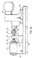
- FIG. 1A this shows the food processor 10 carried by housing 66 which in turn is mounted on base 68.
- the processor shown is an experimental model having an internal diameter of about 3 inches (about 7.6 cm) which results in a treatment zone (ie. defined as the area of the inner wall of tube 12 opposing the main body of rotator 54 of a nominal square foot (ie about 930 cm2) which is reduced in practice due to the presence of seals, end plates, et cetera, to a working area of about 650 cm2.
- the device is adapted for use with steam, water or brine as the heat transfer medium allowing for a very wide range of processing temperatures.
- Allowable pressures within the processor depend on the seals used but even with conventional seals using rubber components, these can be quite high, for example, 50 to 100 psi.
- the cylindrical cartridge-type bearing assembly is mounted within support 70, held in place by nut 72.
- the closure plate arrangement of chamber 18 is shown at 74.
- Extremity 60 of shaft 58 connects with a flexible coupling 76, for example, a LOVEJOYTM flexible coupling, a shear pin (not shown being located in a socket located at 78).
- a variable speed motor 82 which is carried by support 84 mounted on base 68. The motor and associated gearing is adapted to rotate the rotator 54 at speeds of up to 1500 rpm.
- FIG. 2A there is illustrated the food processor 10 of the present invention and a pump system arranged to supply material to, maintain the pressure in, and extract processed material from processor 10.
- the pump system comprises a first pump 86 connected via conduit 92 to the inlet 28 of processor 10.
- the exit port 26 of processor 10 communicates with conduit 98 and a second pump 100. Processed material exits pump 100 via conduit 104.
- the plant depicted in Figure 2 preferably comprises a processor of the present invention shown in Figure 2A arranged in tandem with a conventional scraped surface heat exchanger, the remainder of the system remaining exactly as shown in Figure 2A.
- the axially oriented exit port 26 of the processor 10 is connected via conduit 106 to the equivalent axially oriented port of the conventional scraped surface heat exchanger 10B.
- that mode of connection ensures a smooth flow of material, without change of direction, through both the processor 10 and the conventional heat exchanger 10B. This ensures an even flow of product from the processor 10 to the heat exchanger 10B wherein the product is cooled as aforementioned to avoid loss of desirable volatile components.
- none of the product remains at the elevated treatment temperature for an undesirably protracted period, which in turn assists in maintaining the uniform character of the product.
- a second processing unit of the present invention could be utilized in place of the conventional scraped heat exchanger 10B.
- This latter arrangement provides a processor having a processing zone consisting of two partial zones in tandem with one another and in which the conditions of temperature and shear can be independently adjusted.
- both zones could be operated in exactly the same manner thereby providing, in effect, one treatment zone giving twice the residence time for the material being treated.
- one zone could be operated to heat material whilst the other could be operated to cool the material, either rapidly or slowly as may be desired.
- the flexibility this arrangement provides will be self-evident. Of course, more than two processors could be connected in this manner.
- the connecting conduit 106 is provided with an insulating jacket or preferably for flexibility of operation, means to attain the passage of a heat exchange medium therearound. It is also provided with a port 108 through which temperature and pressure sensors (not shown) are located, thereby allowing careful monitoring of the states of material during processing.
- Heat exchange medium is circulated through helical chamber 24 usually in a countercurrent manner to that of material being processed.
- material to be processed would usually enter through radially oriented inlet port 50 and exit via axially oriented port 48, in which case heat exchange medium would enter chamber 24 via port 28 and exit via port 26.
- the fluid food, slurry or solution to be processed is supplied to pump 86 and is introduced to processor 10 via conduit 92 at a substantially constant rate.
- the rotator 54 is driven at a constant speed in the range of between 750 and 1500 rpm; usually 850 to 1200 rpm.
- Processed material exits via port 48, passes through conduit 98 to pump 100 and finally, to packaging equipment if it is to be packed immediately.
- This arrangement and operation is very advantageous since, for example, reheating of the product to sterilize same, et cetera, need not be carried out.
- the processed material can be passed to storage.
- pumps 86 and 100 work together in an arrangement which ensures smooth transport of material through the processor and also allows for delicate fine tuning of the pressure in the system. Obviously upon start up, the system has to be balanced to obtain precisely the pressures, temperatures, shear applied and rate of material throughput desired, those parameters obviously being mutually interdependent to a great extent.
- the processor 10 and conventional scraped heat exchanger 10B are arranged in tandem by conduit 106.
- this arrangement constitutes a processor like that shown in Figure 1 but further providing a second heat exchange zone which can be adjusted so as to efficiently cool the product passing through the system.
- the processed material was cooled in a controlled manner from its maximum temperature at processing to a reduced temperature which allowed the product to be asceptically packed directly, without further treatment, into asceptic bottles.
- the residence time in the first processor ranged between about 3 to 8 seconds in total.
- the pressure of the product within the processor 10 was from about 80- psi to about 90 psi.
- the pressure which need be maintained in the processor will depend, inter alia , on the volatility of components in the substrate being treated and the treatment temperature being employed. These pressures may be as high as 100 psi or more where necessary or desirable, provided however, that the bearings, seals and other components of the processor system are designed to accommodate such pressures.
Landscapes
- Chemical & Material Sciences (AREA)
- Chemical Kinetics & Catalysis (AREA)
- Food Preservation Except Freezing, Refrigeration, And Drying (AREA)
- Fats And Perfumes (AREA)
- Coating Apparatus (AREA)
- Heat-Exchange Devices With Radiators And Conduit Assemblies (AREA)
- Formation And Processing Of Food Products (AREA)
Priority Applications (6)
| Application Number | Priority Date | Filing Date | Title |
|---|---|---|---|
| US06/606,978 US4744521A (en) | 1986-06-27 | 1984-05-04 | Fluid food processor |
| AT86108769T ATE70991T1 (de) | 1986-06-27 | 1986-06-27 | Behandlungsverfahren fuer fluessige nahrung. |
| DE8686108769T DE3683293D1 (de) | 1986-06-27 | 1986-06-27 | Behandlungsverfahren fuer fluessige nahrung. |
| EP86108769A EP0250622B1 (fr) | 1986-06-27 | 1986-06-27 | Procédé de traitement de nourriture liquide |
| AU59384/86A AU588893B2 (en) | 1986-06-27 | 1986-06-30 | Fluid food processor |
| JP61167740A JPS6321488A (ja) | 1986-06-27 | 1986-07-15 | 流体食品加工装置 |
Applications Claiming Priority (1)
| Application Number | Priority Date | Filing Date | Title |
|---|---|---|---|
| EP86108769A EP0250622B1 (fr) | 1986-06-27 | 1986-06-27 | Procédé de traitement de nourriture liquide |
Publications (2)
| Publication Number | Publication Date |
|---|---|
| EP0250622A1 true EP0250622A1 (fr) | 1988-01-07 |
| EP0250622B1 EP0250622B1 (fr) | 1992-01-02 |
Family
ID=8195224
Family Applications (1)
| Application Number | Title | Priority Date | Filing Date |
|---|---|---|---|
| EP86108769A Expired - Lifetime EP0250622B1 (fr) | 1986-06-27 | 1986-06-27 | Procédé de traitement de nourriture liquide |
Country Status (6)
| Country | Link |
|---|---|
| US (1) | US4744521A (fr) |
| EP (1) | EP0250622B1 (fr) |
| JP (1) | JPS6321488A (fr) |
| AT (1) | ATE70991T1 (fr) |
| AU (1) | AU588893B2 (fr) |
| DE (1) | DE3683293D1 (fr) |
Cited By (4)
| Publication number | Priority date | Publication date | Assignee | Title |
|---|---|---|---|---|
| WO1994011096A1 (fr) * | 1992-11-12 | 1994-05-26 | Eastman Kodak Company | Appareil de melange de fluides |
| EP0831290A3 (fr) * | 1996-08-17 | 1999-06-23 | Bauermeister Verfahrenstechnik GmbH | Refroidisseur à couche mince |
| ITMI20130601A1 (it) * | 2013-04-12 | 2014-10-13 | Giuseppe Ponzielli | Macchina per processare materiali polimerici |
| EP2811843A1 (fr) | 2012-02-08 | 2014-12-17 | Rumenco Limited | Procédé de préparation d'aliment pour animaux |
Families Citing this family (19)
| Publication number | Priority date | Publication date | Assignee | Title |
|---|---|---|---|---|
| US5061503A (en) * | 1989-06-14 | 1991-10-29 | The Procter & Gamble Company | Simulated cheese products with reduced animal fat and calories |
| CA2017461C (fr) * | 1989-06-14 | 1997-03-11 | Josephine Ling Yee Kong-Chan | Analogues succedanes du fromage contenant peu de graisses animales et de calories |
| US6471392B1 (en) | 2001-03-07 | 2002-10-29 | Holl Technologies Company | Methods and apparatus for materials processing |
| US6742774B2 (en) * | 1999-07-02 | 2004-06-01 | Holl Technologies Company | Process for high shear gas-liquid reactions |
| US7538237B2 (en) * | 1999-07-02 | 2009-05-26 | Kreido Laboratories | Process for high shear gas-liquid reactions |
| US6723999B2 (en) | 1999-07-02 | 2004-04-20 | Holl Technologies Company | Electromagnetic wave assisted chemical processing |
| US6830806B2 (en) * | 2001-04-12 | 2004-12-14 | Kreido Laboratories | Methods of manufacture of electric circuit substrates and components having multiple electric characteristics and substrates and components so manufactured |
| WO2003022415A2 (fr) * | 2001-09-13 | 2003-03-20 | Holl Technologies Company | Procedes et appareils d'echange d'energie thermique entre la surface d'un corps et un fluide d'echange thermique |
| US6787246B2 (en) | 2001-10-05 | 2004-09-07 | Kreido Laboratories | Manufacture of flat surfaced composites comprising powdered fillers in a polymer matrix |
| US7098360B2 (en) * | 2002-07-16 | 2006-08-29 | Kreido Laboratories | Processes employing multiple successive chemical reaction process steps and apparatus therefore |
| CA2497615A1 (fr) * | 2002-09-11 | 2004-03-25 | Kreido Laboratories | Procedes et appareil permettant d'effectuer un melange et une reaction a cisaillement eleve de materiaux |
| WO2004030802A2 (fr) * | 2002-10-03 | 2004-04-15 | Kreido Laboratories | Appareil de transfert d'energie thermique entre le surface d'un corps et un fluide caloporteur |
| WO2005118122A2 (fr) * | 2004-05-28 | 2005-12-15 | Clemson University | Systeme de melange de composants multiples |
| US20050287670A1 (en) * | 2004-06-29 | 2005-12-29 | Gulliver Eric A | Cell culturing systems, methods and apparatus |
| CN100528315C (zh) * | 2005-10-11 | 2009-08-19 | 鸿富锦精密工业(深圳)有限公司 | 热界面材料混合装置 |
| US7780927B2 (en) * | 2008-02-20 | 2010-08-24 | Richard A Holl | Spinning tube in tube reactors and their methods of operation |
| US8197122B2 (en) * | 2008-04-24 | 2012-06-12 | Tyco Healthcare Group Lp | Dynamic mixing applicator |
| US10675598B2 (en) * | 2015-03-24 | 2020-06-09 | South Dakota Board Of Regents | High shear thin film machine for dispersion and simultaneous orientation-distribution of nanoparticles within polymer matrix |
| JP6655519B2 (ja) * | 2016-09-29 | 2020-02-26 | 株式会社日立製作所 | 旅客移動状況出力装置および方法 |
Citations (6)
| Publication number | Priority date | Publication date | Assignee | Title |
|---|---|---|---|---|
| US1721121A (en) * | 1926-03-11 | 1929-07-16 | Jensen Aage | Method for reconstructing liquid mixtures |
| FR1235055A (fr) * | 1958-09-15 | 1960-07-01 | Union Carbide Corp | Procédé et appareil pour mélanger des matières formant des masses visqueuses |
| US2973946A (en) * | 1958-07-29 | 1961-03-07 | American Viscose Corp | Mixing apparatus |
| US3127152A (en) * | 1964-03-31 | Counter-rotation continuous shear mixer | ||
| DE3200666A1 (de) * | 1981-02-03 | 1983-07-21 | Hans-Peter 2000 Hamburg Bockwoldt | Vorrichtung zur herstellung von oel-, wie schweroel-oder leichten heizoel-wasser-, insbesondere seewasser-emulsionen und von kohlenstaub-wasser-, insbesondere seewasser-suspensionen mit zur verbrennung geeigneter viskositaet zur einduesung in den heisswindstrom von hochoefen, brennstoffmischanlagen, heizkraftwerksanlagen u.dgl. |
| DE3327137A1 (de) * | 1982-08-05 | 1984-02-09 | Konishiroku Photo Industry Co., Ltd., Tokyo | Verfahren zur herstellung von fluessigen teilchen einer dispergierten loesung |
Family Cites Families (27)
| Publication number | Priority date | Publication date | Assignee | Title |
|---|---|---|---|---|
| US382364A (en) * | 1888-05-08 | Halp to william a | ||
| US1428687A (en) * | 1921-04-30 | 1922-09-12 | Ferencz Jose | Tube mill |
| US1717126A (en) * | 1925-05-28 | 1929-06-11 | Goodyear Tire & Rubber | Grinding mill for rubber |
| US1679093A (en) * | 1926-08-05 | 1928-07-31 | Barrett Co | Polymerization and purification of hydrocarbons |
| US1725155A (en) * | 1927-05-21 | 1929-08-20 | Andrew W Mcallister | Grinding machine |
| US1851071A (en) * | 1928-06-30 | 1932-03-29 | Travis Pierce Mason | Dispersion mill |
| US1997032A (en) * | 1930-02-15 | 1935-04-09 | Doering Res & Dev Corp | Pasteurizing machine |
| US2023607A (en) * | 1934-11-03 | 1935-12-10 | Vogt Processes Inc | Processing apparatus |
| US2171465A (en) * | 1937-04-27 | 1939-08-29 | William A Weidlich | Grinding mill |
| US2231421A (en) * | 1938-01-22 | 1941-02-11 | Greenwich Machine & Tool Co In | Colloid mill |
| US2212662A (en) * | 1939-01-10 | 1940-08-27 | Daniel E Hennessy | Dispersing mill |
| US2474007A (en) * | 1945-06-21 | 1949-06-21 | Shell Dev | Method of and apparatus for contacting fluids |
| US2552889A (en) * | 1946-11-22 | 1951-05-15 | Bennett Inc | Rotor for dispersion machines |
| US2474006A (en) * | 1949-04-11 | 1949-06-21 | Shell Dev | Rotary contactor for fluids |
| US2745261A (en) * | 1954-11-01 | 1956-05-15 | Casper W Merrill | Continuous freezer |
| US3164328A (en) * | 1963-04-08 | 1965-01-05 | Edward M Van Dornick | Method for producing seed crystals |
| GB1022676A (en) * | 1963-07-29 | 1966-03-16 | British Titan Products | Process and apparatus for milling |
| US3367126A (en) * | 1966-05-19 | 1968-02-06 | John D. Howell | Floating agitator |
| US3570775A (en) * | 1967-12-21 | 1971-03-16 | Gen Electric | Mica delamination |
| DE2152718C3 (de) * | 1970-10-23 | 1979-10-11 | Mitsubishi Petrochemical Co., Ltd., Tokio | Vorrichtung zum Verarbeiten von thermoplastischen Kunststoff enthaltendem Kunststoffabfall |
| DE2214023A1 (de) * | 1971-04-01 | 1972-11-02 | Apaw S.A., Freiburg (Schweiz) | Maschine zur chargenweisen Herstellung und Schnellentladung von Speiseeis |
| US3781132A (en) * | 1971-08-16 | 1973-12-25 | Monsanto Co | Devolatilizer rotor assembly |
| ES429630A1 (es) * | 1973-09-21 | 1976-10-01 | Celorio Mendoza | Mejoras introducidas en un aparato para coccion y molienda simultaneas de granos. |
| US3910346A (en) * | 1974-01-23 | 1975-10-07 | Braak Bv Geb | Mixer |
| US4198383A (en) * | 1978-08-21 | 1980-04-15 | Deryagina Galina M | Apparatus for continuous preparation of acrylonitrilebutadienstyrene copolymer |
| SE445052C (sv) * | 1980-03-13 | 1987-11-09 | Sunds Defibrator | Sett och anordning for kontinuerlig inblandning av gas- och/eller vetskeformiga behandlingsmedel i en massasuspension |
| AT369960B (de) * | 1981-06-24 | 1983-02-25 | Vaihinger Gmbh & Co Kommanditg | Geraet zur herstellung schaumiger schlagsahne |
-
1984
- 1984-05-04 US US06/606,978 patent/US4744521A/en not_active Expired - Lifetime
-
1986
- 1986-06-27 DE DE8686108769T patent/DE3683293D1/de not_active Expired - Fee Related
- 1986-06-27 EP EP86108769A patent/EP0250622B1/fr not_active Expired - Lifetime
- 1986-06-27 AT AT86108769T patent/ATE70991T1/de active
- 1986-06-30 AU AU59384/86A patent/AU588893B2/en not_active Ceased
- 1986-07-15 JP JP61167740A patent/JPS6321488A/ja active Pending
Patent Citations (6)
| Publication number | Priority date | Publication date | Assignee | Title |
|---|---|---|---|---|
| US3127152A (en) * | 1964-03-31 | Counter-rotation continuous shear mixer | ||
| US1721121A (en) * | 1926-03-11 | 1929-07-16 | Jensen Aage | Method for reconstructing liquid mixtures |
| US2973946A (en) * | 1958-07-29 | 1961-03-07 | American Viscose Corp | Mixing apparatus |
| FR1235055A (fr) * | 1958-09-15 | 1960-07-01 | Union Carbide Corp | Procédé et appareil pour mélanger des matières formant des masses visqueuses |
| DE3200666A1 (de) * | 1981-02-03 | 1983-07-21 | Hans-Peter 2000 Hamburg Bockwoldt | Vorrichtung zur herstellung von oel-, wie schweroel-oder leichten heizoel-wasser-, insbesondere seewasser-emulsionen und von kohlenstaub-wasser-, insbesondere seewasser-suspensionen mit zur verbrennung geeigneter viskositaet zur einduesung in den heisswindstrom von hochoefen, brennstoffmischanlagen, heizkraftwerksanlagen u.dgl. |
| DE3327137A1 (de) * | 1982-08-05 | 1984-02-09 | Konishiroku Photo Industry Co., Ltd., Tokyo | Verfahren zur herstellung von fluessigen teilchen einer dispergierten loesung |
Cited By (5)
| Publication number | Priority date | Publication date | Assignee | Title |
|---|---|---|---|---|
| WO1994011096A1 (fr) * | 1992-11-12 | 1994-05-26 | Eastman Kodak Company | Appareil de melange de fluides |
| EP0831290A3 (fr) * | 1996-08-17 | 1999-06-23 | Bauermeister Verfahrenstechnik GmbH | Refroidisseur à couche mince |
| EP2811843A1 (fr) | 2012-02-08 | 2014-12-17 | Rumenco Limited | Procédé de préparation d'aliment pour animaux |
| ITMI20130601A1 (it) * | 2013-04-12 | 2014-10-13 | Giuseppe Ponzielli | Macchina per processare materiali polimerici |
| WO2014167551A1 (fr) * | 2013-04-12 | 2014-10-16 | Nexxus Channel S.R.L. | Machine pour le traitement de matières polymères |
Also Published As
| Publication number | Publication date |
|---|---|
| AU5938486A (en) | 1988-01-07 |
| ATE70991T1 (de) | 1992-01-15 |
| JPS6321488A (ja) | 1988-01-29 |
| AU588893B2 (en) | 1989-09-28 |
| EP0250622B1 (fr) | 1992-01-02 |
| US4744521A (en) | 1988-05-17 |
| DE3683293D1 (de) | 1992-02-13 |
Similar Documents
| Publication | Publication Date | Title |
|---|---|---|
| EP0250622B1 (fr) | Procédé de traitement de nourriture liquide | |
| US5240724A (en) | Process for producing pumpable foodstuffs, in particular processed cheese | |
| AP719A (en) | Apparatus and method for treating a fluid product. | |
| US3751010A (en) | Mixer | |
| US5249514A (en) | Apparatus for producing pumpable foodstuffs, in particular processed cheese | |
| US5423288A (en) | Apparatus for producing seed crystals | |
| EP0753338B1 (fr) | Procédé et appareil pour l'agitation d'un liquide de traitement | |
| JPS62500157A (ja) | 液体、乳剤その他の材料の連続的処理、例えば混合、均質化等のための装置 | |
| US4515482A (en) | Sterile suspension and solution holding and mixing tank | |
| US3398900A (en) | High shear dispersion unit | |
| US7165933B2 (en) | Screw pump for transporting emulsions susceptible to mechanical handling | |
| CN115445502A (zh) | 一种在线真空搅拌剪切分散乳化机构 | |
| JP2008544843A (ja) | 混合機及び混合の方法 | |
| US3385354A (en) | Scraped surface heat exchange apparatus | |
| CA1262892A (fr) | Dispositif de traitement de fluides | |
| CN101259389B (zh) | 一种高剪切细化均质机 | |
| Edwards et al. | A review of liquid mixing equipment | |
| US3261391A (en) | Thin-film processing apparatus | |
| US2908487A (en) | Blending mill agitator and additive feed | |
| JP3178402B2 (ja) | ドレッシング系複合液の連続混合乳化装置 | |
| US3153688A (en) | Method and apparatus for intensified refining of deformable solids | |
| US2973946A (en) | Mixing apparatus | |
| JPH01130724A (ja) | 連続式高温高圧反応装置 | |
| JPS6257636A (ja) | 高粘度液反応装置 | |
| JPH078775A (ja) | 回転混合器 |
Legal Events
| Date | Code | Title | Description |
|---|---|---|---|
| PUAI | Public reference made under article 153(3) epc to a published international application that has entered the european phase |
Free format text: ORIGINAL CODE: 0009012 |
|
| AK | Designated contracting states |
Kind code of ref document: A1 Designated state(s): AT BE CH DE FR GB IT LI LU NL SE |
|
| 17P | Request for examination filed |
Effective date: 19880509 |
|
| 17Q | First examination report despatched |
Effective date: 19891110 |
|
| GRAA | (expected) grant |
Free format text: ORIGINAL CODE: 0009210 |
|
| AK | Designated contracting states |
Kind code of ref document: B1 Designated state(s): AT BE CH DE FR GB IT LI LU NL SE |
|
| REF | Corresponds to: |
Ref document number: 70991 Country of ref document: AT Date of ref document: 19920115 Kind code of ref document: T |
|
| ITF | It: translation for a ep patent filed | ||
| REF | Corresponds to: |
Ref document number: 3683293 Country of ref document: DE Date of ref document: 19920213 |
|
| ET | Fr: translation filed | ||
| PLBE | No opposition filed within time limit |
Free format text: ORIGINAL CODE: 0009261 |
|
| STAA | Information on the status of an ep patent application or granted ep patent |
Free format text: STATUS: NO OPPOSITION FILED WITHIN TIME LIMIT |
|
| 26N | No opposition filed | ||
| EPTA | Lu: last paid annual fee | ||
| EAL | Se: european patent in force in sweden |
Ref document number: 86108769.0 |
|
| PGFP | Annual fee paid to national office [announced via postgrant information from national office to epo] |
Ref country code: FR Payment date: 19950609 Year of fee payment: 10 |
|
| PGFP | Annual fee paid to national office [announced via postgrant information from national office to epo] |
Ref country code: AT Payment date: 19950613 Year of fee payment: 10 |
|
| PGFP | Annual fee paid to national office [announced via postgrant information from national office to epo] |
Ref country code: SE Payment date: 19950615 Year of fee payment: 10 |
|
| PGFP | Annual fee paid to national office [announced via postgrant information from national office to epo] |
Ref country code: GB Payment date: 19950616 Year of fee payment: 10 |
|
| PGFP | Annual fee paid to national office [announced via postgrant information from national office to epo] |
Ref country code: DE Payment date: 19950617 Year of fee payment: 10 |
|
| PGFP | Annual fee paid to national office [announced via postgrant information from national office to epo] |
Ref country code: CH Payment date: 19950623 Year of fee payment: 10 |
|
| PGFP | Annual fee paid to national office [announced via postgrant information from national office to epo] |
Ref country code: NL Payment date: 19950628 Year of fee payment: 10 |
|
| PGFP | Annual fee paid to national office [announced via postgrant information from national office to epo] |
Ref country code: LU Payment date: 19950701 Year of fee payment: 10 |
|
| PGFP | Annual fee paid to national office [announced via postgrant information from national office to epo] |
Ref country code: BE Payment date: 19950809 Year of fee payment: 10 |
|
| PG25 | Lapsed in a contracting state [announced via postgrant information from national office to epo] |
Ref country code: LU Free format text: LAPSE BECAUSE OF NON-PAYMENT OF DUE FEES Effective date: 19960627 Ref country code: GB Effective date: 19960627 Ref country code: AT Effective date: 19960627 |
|
| PG25 | Lapsed in a contracting state [announced via postgrant information from national office to epo] |
Ref country code: SE Effective date: 19960628 |
|
| PG25 | Lapsed in a contracting state [announced via postgrant information from national office to epo] |
Ref country code: LI Effective date: 19960630 Ref country code: CH Effective date: 19960630 Ref country code: BE Effective date: 19960630 |
|
| BERE | Be: lapsed |
Owner name: JOHN LABATT LTD Effective date: 19960630 |
|
| PG25 | Lapsed in a contracting state [announced via postgrant information from national office to epo] |
Ref country code: NL Effective date: 19970101 |
|
| REG | Reference to a national code |
Ref country code: CH Ref legal event code: PL |
|
| GBPC | Gb: european patent ceased through non-payment of renewal fee |
Effective date: 19960627 |
|
| PG25 | Lapsed in a contracting state [announced via postgrant information from national office to epo] |
Ref country code: FR Effective date: 19970228 |
|
| PG25 | Lapsed in a contracting state [announced via postgrant information from national office to epo] |
Ref country code: DE Effective date: 19970301 |
|
| EUG | Se: european patent has lapsed |
Ref document number: 86108769.0 |
|
| NLV4 | Nl: lapsed or anulled due to non-payment of the annual fee |
Effective date: 19970101 |
|
| REG | Reference to a national code |
Ref country code: FR Ref legal event code: ST |
|
| PG25 | Lapsed in a contracting state [announced via postgrant information from national office to epo] |
Ref country code: IT Free format text: LAPSE BECAUSE OF NON-PAYMENT OF DUE FEES;WARNING: LAPSES OF ITALIAN PATENTS WITH EFFECTIVE DATE BEFORE 2007 MAY HAVE OCCURRED AT ANY TIME BEFORE 2007. THE CORRECT EFFECTIVE DATE MAY BE DIFFERENT FROM THE ONE RECORDED. Effective date: 20050627 |