EP0250820A2 - Luftfeder für ein Fahrzeug - Google Patents
Luftfeder für ein Fahrzeug Download PDFInfo
- Publication number
- EP0250820A2 EP0250820A2 EP87107103A EP87107103A EP0250820A2 EP 0250820 A2 EP0250820 A2 EP 0250820A2 EP 87107103 A EP87107103 A EP 87107103A EP 87107103 A EP87107103 A EP 87107103A EP 0250820 A2 EP0250820 A2 EP 0250820A2
- Authority
- EP
- European Patent Office
- Prior art keywords
- piston
- annular
- shaped
- wall
- sleeve
- Prior art date
- Legal status (The legal status is an assumption and is not a legal conclusion. Google has not performed a legal analysis and makes no representation as to the accuracy of the status listed.)
- Granted
Links
Images

Classifications
-
- F—MECHANICAL ENGINEERING; LIGHTING; HEATING; WEAPONS; BLASTING
- F16—ENGINEERING ELEMENTS AND UNITS; GENERAL MEASURES FOR PRODUCING AND MAINTAINING EFFECTIVE FUNCTIONING OF MACHINES OR INSTALLATIONS; THERMAL INSULATION IN GENERAL
- F16F—SPRINGS; SHOCK-ABSORBERS; MEANS FOR DAMPING VIBRATION
- F16F9/00—Springs, vibration-dampers, shock-absorbers, or similarly-constructed movement-dampers using a fluid or the equivalent as damping medium
- F16F9/02—Springs, vibration-dampers, shock-absorbers, or similarly-constructed movement-dampers using a fluid or the equivalent as damping medium using gas only or vacuum
- F16F9/04—Springs, vibration-dampers, shock-absorbers, or similarly-constructed movement-dampers using a fluid or the equivalent as damping medium using gas only or vacuum in a chamber with a flexible wall
- F16F9/05—Springs, vibration-dampers, shock-absorbers, or similarly-constructed movement-dampers using a fluid or the equivalent as damping medium using gas only or vacuum in a chamber with a flexible wall the flexible wall being of the rolling diaphragm type
-
- B—PERFORMING OPERATIONS; TRANSPORTING
- B60—VEHICLES IN GENERAL
- B60G—VEHICLE SUSPENSION ARRANGEMENTS
- B60G11/00—Resilient suspensions characterised by arrangement, location or kind of springs
- B60G11/26—Resilient suspensions characterised by arrangement, location or kind of springs having fluid springs only, e.g. hydropneumatic springs
- B60G11/28—Resilient suspensions characterised by arrangement, location or kind of springs having fluid springs only, e.g. hydropneumatic springs characterised by means specially adapted for attaching the spring to axle or sprung part of the vehicle
Definitions
- the invention relates to vehicle suspensions and particularly to an air spring having a low operating height while providing a normal stroke required for most motor vehicles.
- Pneumatic springs commonly referred to as air springs
- air springs have been used with motor vehicles for a number of years to provide cushioning between movable parts of the vehicle primarily to absorb shock loads impressed on the vehicle axles by the wheels striking an object in the road or falling into a depression.
- These air springs usually consist of a flexible rubber sleeve or bellows containing a supply of compressed air and having one or more pistons located within the flexible resilient bellows or sleeves to cause compression and expansion as the vehicle experiences the road shocks.
- the pistons cause compression and expansion of the fluid within the spring sleeve with the sleeve being of a flexible material permitting the pistons to move axially with respect to each other within the interior of the sleeve.
- the ends of the sleeve usually are sealingly connected to the piston or supporting structure.
- Many of the pressure chamber forming sleeves of these prior art air springs are bellow shaped or have rolled ends to permit the pistons to move axially with respect to each other between a jounce or collapsed position and a rebound or expended position without damaging the flexible sleeve in which the pistons are located.
- U.S. Patent No. 2,926,011 shows an air spring having a variable contour piston which is connected between a vehicle under carriage and frame.
- a piston diaphram has inwardly directed portions and ends which are attached to a top piston plate and to a resting plate.
- U.S. Patent No. 2,985,445 discloses a pneumatic spring control device which comprises an air spring assembly having a dome shaped metal body with a peripheral lip and a circular bellows retainer ring.
- a spring piston is attached to the other end of the bellows assembly and is rigidly mounted to a vehicle wheel supporting arm to reciprocate with the wheel in an arcuate path into and out of the dome.
- U.S. Patent No. 2,978,256 shows a dual height suspension control mechanism having an air spring which includes an upper generally inverted cup shaped cylinder secured to the outer end of a frame member. A cylindrical piston moves into and out of the generally inverted dome-shaped assembly. The assembly and the cylinder are attached to each other by a single convolution flexible bellows having an inner bead portion engaging an inturned lip of the piston.
- U.S. Patent No. 3,046,000 discloses a vehicle suspension spring assembly which includes an inverted cup-shaped member and a hollow piston.
- the piston is rigidly secured to an outer wall of a hydraulic shock absorber cylinder and a flexible diaphram element of the rolling lobe type is attached at one end to the upper end of the piston and at its other end to a lower peripheral wall of a dome.
- a stiker moves upwardly and downwardly with a shock absorber casing along the axis of the piston rod without engaging a rubber buffer.
- U.S. Patent No. 3,074,709 shows an air suspension system for a motor vehicle which includes a movable piston in a housing.
- a flexible expansible material attaches the bead of a metallic cup to the bead of another element.
- U.S. Patent No. 4,518,154 discloses a pneumatic motor vehicle spring which includes cup-shaped pistons which are connected to each other by a flexible bellow. Relatively rigid sleeves are provided which extend about the exterior of the flexible bellows. Two pistons are elastically connected to provide an axial distance between the pistons as a function of the pressure within the volume defined by the spring.
- Objectives of the invention include providing an improved air spring construction for motor vehicles having a piston at both ends of a flexible sleeve, one of which is a low rate piston, and the other being a high rate piston with a circumferential or annular-shaped member surrounding the high rate piston to provide better vertical rate control and to restrict the diameter of the elastomeric sleeve extending between the two pistons.
- Another objective is to provide such an improved air spring in which at minimum height conditions, one of the pistons telescopically fits inside the other piston allowing for a lower operating height of the spring.
- a still further objective of the invention is to provide such an improved air spring in which at the extended position, rolled ends of the elastomeric sleeve pull away from the body of the pistons to allow for extreme height movement, and in which at the operating height of the sleeve, the rubber rolls about the low rate piston at one end, with the other end of the elastomeric sleeve rolling about a part of the high rate piston being confined within an outer annular-shaped member surrounding the piston thereby enabling the elastomeric sleeve to have excess rubber when in the at- rest position to provide an increased stroke length.
- a further objective is to provide such an improved air spring in which a pressurized air control valve is mounted on one of the pistons and communicates with the interior of the flexible sleeve whereby positive air pressure can be maintained at all times within the sleeve when operating to prevent the elastomeric sleeve from becoming pinched between the pistons.
- Another objective is to provide such an air sleeve in which the low rate piston has an annular wall with a conical shaped outer surface about which the connected rolled end of the sleeve folds when the pistons are telescopically engaged when in the jounce or collapsed condition.
- a still further objective of the invention is t& provide such an improved air spring in which the low rate piston is of a two-piece construction having an annular-shaped outer wall mounted by a pair of posts to a disc shaped base of the second member with the rolled end of the sleeve being clamped by a band within the confines of the annular-shaped wall, whereby a portion of the rolled end extends along the inside surface of this outer wall and over and about a smooth outer edge thereof; and in which the other rolled end of the flexible sleeve is sealingly connected by a band to the outer surface of the high rate piston member from which it rolls about an inverted U-shaped wall formed by the piston and a surrounding annular-shaped outer member.
- Another objective is to provide such an improved air spring in which the parts can be stamped inexpensively of sheet metal or formed of plastic or other rigid material and assembled with the elastomeric sleeve by a pair of clamping bands to form a sturdy and durable construction.
- first and second piston members located in a generally predetermined axial spaced relationship when in an at-rest position, said piston members being adapted to be mounted on spaced portions of a vehicle and movable towards and away from each other; a fluid pressure chamber formed between the piston members by a flexible sleeve sealingly connected to said piston members at opposite ends of said sleeve, said sleeve having a greater axial length than the length required to extend between said piston members when in the at-rest position forming a rolled end at each end of said sleeve; an annular-shaped member extending about the first piston member with one of the rolled ends of said flexible sleeve extending about and located between portions of said first piston member and said annular-shaped member when in the at-rest position; and the second piston member having an annular-shaped outer wall configured to move axially telescopically about the first piston member and within the confines of the
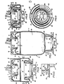
- Improved air spring 1 includes a pair of piston members indicated generally at 2 and 3, hereinafter referred to as a high rate piston and low-rate piston, respectively.
- High rate piston 2 2 is a cup-shaped member having a disc-shaped end wall 4 with a raised circular center portion 5.
- a hole 6 is formed in raised portions 5 to provide a pressurized air inlet opening.
- a standard pressurized air control valve 12 is mounted' on raised portion 5 and communicates with hole 6.
- Valve 12 is shown fragmentarily in several of the views and is a readily available component and forms no particular part of the invention.
- Piston member 2 includes a generally cylindrical side wall indicated generally at 7 and has a smooth cylindrical inner surface 8 and an annular irregularly shaped outer surface 9.
- a pair of diametrically opposite posts 10 project upwardly from end wall 4 in an opposite direction from cylindrical wall 7 for mounting air spring 1 on a vehicle bracket 13 as shown in FIGS. 1-5.
- a cup-shaped member indicated generally at 15, is mounted on and surrounds piston member 2.
- Member 15 has an annular-shaped outer wall 16 terminating in slightly flared outer end 17, and an end wall 18.
- a central opening 19 is formed in end wall 18 through which raised portion 5 of piston end wall 4 extends as shown particularly in FIGS. 2 and 6-8.
- a pair of spaced holes 20 are formed in end wall 18 of cup-shaped member 15 through which posts 10 extend (FIG. 5) for joining piston member 2 with cup shaped member 15 and for mounting the joined members to vehicle bracket 13 as shown in FIG. 5.
- Posts 10 extend through aligned holes 22 formed in vehicle bracket 13 with a spring clip 23 locking the posts onto bracket 13.
- Cylindrical wall 16 of cup-shaped member 15 has a smooth cylindrical inner surface 24 which terminates in a curved inner corner 25 which mates with a smooth annular-shaped concave surface 27 extending along the inner surface of end wall 4. Surface 27 then merges into a smooth cylindrical portion of outer surface 9 of piston cylindrical wall 7 to form a generally inverted U-shaped surface configuration as shown particularly in FIGS. 5-8.
- the extended end of cylindrical wall 7 is formed with a plurality of annular grooves 28 to provide a surface for clamping an upturned end 29 of flexible sleeve 30 thereto.
- Flexible sleeve 30 is formed of an elastomeric material and forms a fluid pressure chamber 31 between pistons 2 and 3 for containing a supply of pressurized fluid preferably air, which is injected into chamber 31 through valve 12 and inlet hole 6.
- flexible sleeve 30 has a greater axial length than that required to extend between pistons 2 and 3 when the pistons are in the at-rest position as shown in FIG. 6.
- Sleeve 30 is sealingly connected to each piston members 2 and 3 by clamping bands 32 and 33, respectively.
- Band 32 sealingly clamps the upturned end 29 of sleeve 30 against annular grooves 28 of cylindrical wall 7, and band 33 clamps the opposite end of sleeve 30 against a grooved outer surface of an upstanding cylindrical wall 35 of low rate piston member 3 (FIGS. 6 and 10).
- Low rate piston member 3 preferably is a two piece member having an annular-shaped outer wall indicated generally at 36, which is mounted on a base member 40.
- Wall 36 has a smooth generally tapered conical inner'surface 37 and a smooth concavely shaped outer surface 38 joined by a rounded top edge 39.
- Base member 40 includes an annular disc-shaped base 42 formed with an outwardly extending boss 41 which is concentric with wall 35 and extends in an opposite direction therefrom.
- a recessed central portion 43 is formed in boss 41 and a pair of outwardly extending arms 44 extend radially from boss 41 along the outer surface of base 42 (FIG. 3). Holes 45 (FIG.
- Posts 46 are formed in the outer ends of arms 44 through which a pair of posts 46 project, which posts are formed integrally with and extend outwardly from annular outer wall 36.
- Posts 46 extend through holes 47 formed in a bracket 48, which bracket is attached to a desired component of the motor vehicle.
- a snap ring 49 locks the assembled outer wall 36 to base member 40 to form piston member 3 in addition to attaching piston member 3 on vehicle bracket 48 as shown particularly in FIGS. 1 and 4.
- flexible sleeve 30 has a greater axial length than that required to extend between its attached end positions with piston members 2 and 3 when in the normal or at-rest position on a vehicle as shown in FIGS. 1 and 6.
- This excess length of sleeve 30 forms rolled ends 51 and 52.
- Rolled end 51 extends about and follows the smooth continuous inverted U-shaped surface formed by surfaces 9, 27, and 24 as shown in FIGS. 6 and 7.
- Rolled end (51) is retained within the generally inverted U-shaped annular spaced 54 formed between cylindrical side wall 16 of cup-shaped member 15 and surfaces 9 and 27 of piston member 2.
- Rolled end 52 extendx about low rate piston member 3 when in the at-rest position and lies along conical surface 37 of annular outer wall 36 and ever and about roundod top edge 39 and downwardly along a portion of concave outer surface 38 prior to forming a reverse bend 55 in the elastomeric material of sleeve 30.
- rolled ends 51 and 52 provide a greater amount of rubber in the axial dimension of aleeve 30 than required to connect the ends of sleeve 30 to piston members 2 and 3.
- rolled ends 51 and 52 enable the pistons to move axially apart from their at-rest position of FIG. 6 into an extended position of FIG. 7 upon the vehicle wheel striking a projection or depression in a road surface enabling the air pressure in pressure chamber 31 to absorb much of the shock without stretching or fatiguing the elastomeric material of flexible sleeve 30.
- the configuration of piston members 2 and 3 enable spring. 1 to collapae into a compact position when in the jounce position as shown in FIG. 8.
- Piston member 2 enters into the confines of piston member 3, and in particular within the interior of annular outer wall portion 36 of piston member 3.
- Outer wall 36 projects into U-shaped annular space 54 formed between cylindrical wall 7 of piston member 2 and annular side wall 16 of cup-shaped member 15.
- rolled end 51 extends moves from the extended position of FIG. 7 towards the adjacent walls to gather the excess sleeve material and the opposite rolled end 52 extends further along outer surface 38 of wall 36.
- FIGS. 6, 7, and 8 shows one of the main and important feature of the invention as well as the results achieved thereby.
- the rolled ends of sleeve 30 in combination with the telescopic engagement of piston member 2 within the confines of piston member 3, and in particular within the interior of annular outer will 36, provides an air spring which has a reduced axial length when in the normal or at-rest position in comparison to the greater axial length that is achieved in the extended position. This is accomplished by the unrolling of rolled ends 51 and 52 and the pulling away of these rolled ends from contact with the piston members followed by the ability of the pistons to move into the jounce or telescopic collapsed position of FIG. 8. Therefore, improved air spring 1 provides an increased stroke length in a shorter operating height than heretofore believed possible with existing air spring constructions.
- air spring 1 can be formed easily of stamped steel or rigid plastic material and assembled with sleeve 30 for subsequent mounting on vehicle mounting brackets, and in which the posts used for assembling the two component parts of low rate piston member 3 and the posts for assembling high rate piston member 2 with cup shaped member 15, also provide the means of attaching the piston members to their respective vehicle mounting brackets.
- Cup-shaped member 15 can be eliminated if desired without materially effecting the concept of the invention since low rate piston member 3 still will telescopically engage and extend about high rate piston member 2 in the absence of member 15. However, it is believed that member 15 helps provide better vertical rate control and restricts the diameter of sleeve 30 at the collapsed and at-rest positions.
- Valve 12 is a standard component and preferably will communicate with a microprocessor located in the vehicle. Valve 12 is provided with internal valves which open and close to maintain adequate air pressure in pressure chamber 31 and will supply makeup air into the chamber in the case of leaks and will permit air to escape if too much pressure is created within the chamber.
- the improved air spring construction is simplified, provides an effective, safe, inexpensive, and efficient device which achieves all the enumerated objectives, provides for eliminating difficulties encountered with prior devices, and solves problems and obtains new results in the art.
Landscapes
- Engineering & Computer Science (AREA)
- General Engineering & Computer Science (AREA)
- Mechanical Engineering (AREA)
- Fluid-Damping Devices (AREA)
Applications Claiming Priority (2)
| Application Number | Priority Date | Filing Date | Title |
|---|---|---|---|
| US06/877,950 US4718650A (en) | 1986-06-23 | 1986-06-23 | Air spring for vehicle |
| US877950 | 1986-06-23 |
Publications (3)
| Publication Number | Publication Date |
|---|---|
| EP0250820A2 true EP0250820A2 (de) | 1988-01-07 |
| EP0250820A3 EP0250820A3 (en) | 1988-05-04 |
| EP0250820B1 EP0250820B1 (de) | 1990-01-10 |
Family
ID=25371072
Family Applications (1)
| Application Number | Title | Priority Date | Filing Date |
|---|---|---|---|
| EP87107103A Expired - Lifetime EP0250820B1 (de) | 1986-06-23 | 1987-05-16 | Luftfeder für ein Fahrzeug |
Country Status (7)
| Country | Link |
|---|---|
| US (1) | US4718650A (de) |
| EP (1) | EP0250820B1 (de) |
| JP (1) | JP2753230B2 (de) |
| BR (1) | BR8703132A (de) |
| CA (1) | CA1291489C (de) |
| DE (1) | DE3761393D1 (de) |
| ES (1) | ES2012071B3 (de) |
Cited By (4)
| Publication number | Priority date | Publication date | Assignee | Title |
|---|---|---|---|---|
| WO2000040431A1 (de) * | 1999-01-04 | 2000-07-13 | Otto Sauer Achsenfabrik Keilberg | Fahrzeug-achsaufhängung |
| WO2007104671A1 (en) * | 2006-03-10 | 2007-09-20 | Trelleborg Automotive Uk Ltd. | Air spring with improved piston |
| DE102007027834A1 (de) * | 2007-06-13 | 2008-12-18 | Continental Aktiengesellschaft | Luftfedereinrichtung |
| DE102011109670A1 (de) * | 2011-08-08 | 2013-02-14 | Carl Freudenberg Kg | Luftfeder |
Families Citing this family (37)
| Publication number | Priority date | Publication date | Assignee | Title |
|---|---|---|---|---|
| US5005808A (en) * | 1987-12-01 | 1991-04-09 | The Goodyear Tire & Rubber Company | Airspring end member and airspring assembly |
| US4852861A (en) * | 1988-12-29 | 1989-08-01 | The Firestone Tire & Rubber Company | End cap assembly for air spring |
| US4899995A (en) * | 1988-12-29 | 1990-02-13 | Bridgestone/Firestone, Inc. | Clamp ring assembly for air spring |
| US5169129A (en) * | 1991-09-26 | 1992-12-08 | Bridgestone/Firestone, Inc. | Variable rate air spring suspension system |
| US5342139A (en) * | 1992-09-30 | 1994-08-30 | Bridgestone/Firestone, Inc. | Snap mounted attachment device |
| DE4325576C2 (de) * | 1993-07-30 | 1999-01-07 | Continental Ag | Luftfeder für Fahrzeuge mit einem elastomeren, kernlosen Schlauchrollbalg |
| US5374037A (en) * | 1993-09-20 | 1994-12-20 | Bridgestone/Firestone, Inc. | Clamp ring assembly for air spring |
| US5382006A (en) * | 1993-09-29 | 1995-01-17 | The Goodyear Tire & Rubber Company | Airspring piston and airspring assembly |
| CA2229629C (en) | 1997-03-13 | 2007-08-14 | The Goodyear Tire & Rubber Company | High modulus belt composition and belts made therewith |
| US5941509A (en) * | 1997-04-18 | 1999-08-24 | Bridgestone/Firestone, Inc. | Clamp assembly for air actuator |
| DE19719505C2 (de) * | 1997-05-09 | 2000-09-14 | Mannesmann Sachs Ag | Luftfeder mit gelenkiggelagertem Abrollrohr |
| WO1999015808A1 (de) * | 1997-09-25 | 1999-04-01 | Phoenix Aktiengesellschaft | Luftfedersystem |
| US6036180A (en) | 1998-02-26 | 2000-03-14 | Bridgestone/Firestone, Inc. | Tear-drop shaped clamp assembly and tapered end cap for an air spring |
| US6926264B1 (en) | 1999-05-28 | 2005-08-09 | The Goodyear Tire & Rubber Company | Air spring upper retainer |
| MXPA02000370A (es) * | 1999-06-11 | 2004-05-21 | Gates Corp | Muelle de aire de compartimiento dual. |
| US6698730B2 (en) | 2001-10-04 | 2004-03-02 | Bfs Diversified Products, Llc | Dual rate air spring |
| US6746004B2 (en) * | 2001-12-05 | 2004-06-08 | Bfs Diversified Products, Llc | Vehicle air spring assembly |
| US6845973B2 (en) * | 2002-08-07 | 2005-01-25 | Bfs Diversified Products, Llc | Air spring with restraining cylinder |
| DE10249741A1 (de) * | 2002-10-25 | 2004-05-06 | Continental Aktiengesellschaft | Rollbalg-Luftfeder mit Stützglocke |
| DE10315555A1 (de) * | 2003-04-05 | 2004-10-14 | Continental Aktiengesellschaft | Doppelrollbalg-Luftfeder mit Schmutzfänger |
| PL1615787T3 (pl) * | 2003-04-17 | 2010-03-31 | Firestone Ind Products Co Llc | Sposób i układ do wyrównywania nieruchomego pojazdu względem sztucznego horyzontu |
| US8306696B2 (en) * | 2003-04-17 | 2012-11-06 | Driveright Holdings, Ltd. | Method and system for aligning a vehicle with an artificial horizon |
| US7497423B2 (en) * | 2004-11-04 | 2009-03-03 | Bfs Diversified Products, Llc | Extensible end member for gas spring assembly |
| US7744099B2 (en) | 2004-11-04 | 2010-06-29 | Driveright Holdings, Ltd. | Method and system for adjusting a vehicle aligned with an artificial horizon |
| ITMI20050211A1 (it) * | 2005-02-14 | 2006-08-15 | Stuani S P A | Pistone perfezionato per molle ad aria applicabile a sospensioni di autoveicoli rimorchi semirimorchi |
| US7325794B2 (en) * | 2005-06-06 | 2008-02-05 | Bfs Diversified Products, Llc | Air spring assembly and method |
| US7404547B2 (en) * | 2005-07-27 | 2008-07-29 | Bfs Diversified Products, Llc | Multi-component end member assembly and air spring assembly including the same |
| KR100803155B1 (ko) * | 2006-09-11 | 2008-02-14 | 주식회사 만도 | 현가장치용 에어스프링 |
| US20090200717A1 (en) * | 2008-02-08 | 2009-08-13 | Veyance Technologies, Inc. | Air spring piston |
| US8155835B2 (en) * | 2008-02-21 | 2012-04-10 | Driveright Holdings, Ltd. | Vehicle chassis height adjustment method and system |
| US20110093239A1 (en) * | 2009-10-21 | 2011-04-21 | Holbrook Gregory A | Vehicle weight sensing methods and systems |
| USD673887S1 (en) * | 2011-08-08 | 2013-01-08 | Firestone Industrial Products Company, Llc | Gas spring end member |
| USD674325S1 (en) * | 2011-08-08 | 2013-01-15 | Firestone Industrial Products Company, Llc | Gas spring end member |
| USD673886S1 (en) * | 2011-08-08 | 2013-01-08 | Firestone Industrial Products Company, Llc | Gas spring end member |
| DE102011109674B4 (de) | 2011-08-08 | 2017-08-10 | Vibracoustic Cv Air Springs Gmbh | Luftfeder für Fahrzeuge |
| USD746183S1 (en) | 2014-07-09 | 2015-12-29 | Firestone Industrial Products Company, Llc | Gas spring end member |
| US20230166574A1 (en) * | 2021-09-06 | 2023-06-01 | Wheel Pros, Llc | Extended Travel Air Spring |
Family Cites Families (21)
| Publication number | Priority date | Publication date | Assignee | Title |
|---|---|---|---|---|
| US4965A (en) * | 1847-02-10 | f fpii | ||
| US2960333A (en) * | 1956-12-28 | 1960-11-15 | Dayco Corp | Telescoping fluid cylinder |
| US2973953A (en) * | 1957-01-02 | 1961-03-07 | Tyman H Fikse | Air spring assembly |
| US2985445A (en) * | 1957-06-20 | 1961-05-23 | Gen Motors Corp | Pneumatic spring control device |
| US2978256A (en) * | 1957-07-11 | 1961-04-04 | Gen Motors Corp | Dual height suspension control mechanism |
| NL105090C (de) * | 1957-12-12 | |||
| NL100787C (de) * | 1958-01-20 | |||
| US3033558A (en) * | 1958-12-11 | 1962-05-08 | Gen Tire & Rubber Co | Single piston air spring with floating band |
| GB881114A (en) * | 1959-08-28 | 1961-11-01 | Dewandre Co Ltd C | Improvements in or relating to air suspension systems for vehicles |
| US3154318A (en) * | 1962-04-24 | 1964-10-27 | Charles T Hutchens | Hydro-pneumatic suspension system for vehicle |
| GB1143665A (de) * | 1965-12-04 | |||
| GB1293392A (en) * | 1969-02-18 | 1972-10-18 | Dunlop Holdings Ltd | Improvements in fluid springs |
| GB1286752A (en) * | 1969-06-20 | 1972-08-23 | Autobrzdy Jablonec Narodni Pod | Pneumatic spring |
| DE2108694C2 (de) * | 1971-02-24 | 1986-03-13 | Continental Gummi-Werke Ag, 3000 Hannover | Luftfederbalg |
| JPS531480Y2 (de) * | 1972-05-22 | 1978-01-17 | ||
| DE2836662C2 (de) * | 1978-08-22 | 1980-06-26 | Daimler-Benz Ag, 7000 Stuttgart | Luftfeder, insbesondere fur Kraftfahrzeuge |
| US4256292A (en) * | 1978-11-29 | 1981-03-17 | General Motors Corporation | Jounce bumper for suspensions |
| GB2043831B (en) * | 1979-03-03 | 1982-11-10 | Plessey Co Ltd | Rolling diaphragms |
| CA1125319A (en) * | 1979-03-08 | 1982-06-08 | Paul R. Brown | Rolling lobe airspring and assembly method |
| JPS5684138U (de) * | 1979-12-04 | 1981-07-07 | ||
| US4564177A (en) * | 1983-04-21 | 1986-01-14 | The Firestone Tire & Rubber Company | Clamp for non-beaded pneumatic assemblies |
-
1986
- 1986-06-23 US US06/877,950 patent/US4718650A/en not_active Expired - Lifetime
-
1987
- 1987-05-07 CA CA000536608A patent/CA1291489C/en not_active Expired - Lifetime
- 1987-05-16 EP EP87107103A patent/EP0250820B1/de not_active Expired - Lifetime
- 1987-05-16 DE DE8787107103T patent/DE3761393D1/de not_active Expired - Lifetime
- 1987-05-16 ES ES87107103T patent/ES2012071B3/es not_active Expired - Lifetime
- 1987-06-16 JP JP62148125A patent/JP2753230B2/ja not_active Expired - Fee Related
- 1987-06-22 BR BR8703132A patent/BR8703132A/pt not_active IP Right Cessation
Cited By (6)
| Publication number | Priority date | Publication date | Assignee | Title |
|---|---|---|---|---|
| WO2000040431A1 (de) * | 1999-01-04 | 2000-07-13 | Otto Sauer Achsenfabrik Keilberg | Fahrzeug-achsaufhängung |
| US6651995B1 (en) | 1999-01-04 | 2003-11-25 | Otto Sauer Achsenfabrik Keilberg | Vehicle axle suspension |
| WO2007104671A1 (en) * | 2006-03-10 | 2007-09-20 | Trelleborg Automotive Uk Ltd. | Air spring with improved piston |
| DE102007027834A1 (de) * | 2007-06-13 | 2008-12-18 | Continental Aktiengesellschaft | Luftfedereinrichtung |
| DE102011109670A1 (de) * | 2011-08-08 | 2013-02-14 | Carl Freudenberg Kg | Luftfeder |
| DE102011109670B4 (de) | 2011-08-08 | 2022-01-20 | Vibracoustic Cv Air Springs Gmbh | Luftfeder |
Also Published As
| Publication number | Publication date |
|---|---|
| EP0250820A3 (en) | 1988-05-04 |
| JP2753230B2 (ja) | 1998-05-18 |
| ES2012071B3 (es) | 1990-03-01 |
| BR8703132A (pt) | 1988-03-08 |
| US4718650A (en) | 1988-01-12 |
| DE3761393D1 (de) | 1990-02-15 |
| EP0250820B1 (de) | 1990-01-10 |
| JPS636234A (ja) | 1988-01-12 |
| CA1291489C (en) | 1991-10-29 |
Similar Documents
| Publication | Publication Date | Title |
|---|---|---|
| US4718650A (en) | Air spring for vehicle | |
| EP0253261B1 (de) | Luftfederaufhängungssystem | |
| JP4986960B2 (ja) | 空気ばね用押嵌め式緩衝器 | |
| US4852861A (en) | End cap assembly for air spring | |
| EP0291720B1 (de) | Aufhängungssystem für Fahrzeuge, wobei ein schwingungsdämpfendes Lager gleichzeitig eine Luftfeder abdichtet | |
| US4206907A (en) | Suspension strut with pneumatic spring | |
| EP0284736B1 (de) | Dämpfungsventil für Luftfederaufhängungssysteme | |
| US5374037A (en) | Clamp ring assembly for air spring | |
| US4030713A (en) | Vehicle suspension device | |
| EP0318696B1 (de) | Luftfederaufhängung mit zweiseitiger Isolierung | |
| US4899995A (en) | Clamp ring assembly for air spring | |
| US4988082A (en) | Spliced air sleeve assembly for air spring damper | |
| US4235426A (en) | Shock absorber with compression spring and dust tube | |
| US5078370A (en) | Upper mount for suspension strut | |
| EP0583405A1 (de) | Mehrteilige gummifeder und lagereinrichtung | |
| CN112879485B (zh) | 空气悬架组件和用于空气悬架组件的波纹管 | |
| US5080328A (en) | Spliced air sleeve assembly having a plurality of rolling lobes | |
| US6746004B2 (en) | Vehicle air spring assembly | |
| US4527781A (en) | Pneumatic vehicle suspension unit with air sleeve guide | |
| US3954256A (en) | Suspension system for automotive vehicles and the like | |
| US4921226A (en) | Lined air sleeve assembly for air spring damper | |
| US3979134A (en) | Vehicle suspension system | |
| JPH10292840A (ja) | 液圧緩衝器 |
Legal Events
| Date | Code | Title | Description |
|---|---|---|---|
| PUAI | Public reference made under article 153(3) epc to a published international application that has entered the european phase |
Free format text: ORIGINAL CODE: 0009012 |
|
| AK | Designated contracting states |
Kind code of ref document: A2 Designated state(s): DE ES FR GB IT SE |
|
| PUAL | Search report despatched |
Free format text: ORIGINAL CODE: 0009013 |
|
| AK | Designated contracting states |
Kind code of ref document: A3 Designated state(s): DE ES FR GB IT SE |
|
| 17P | Request for examination filed |
Effective date: 19880420 |
|
| 17Q | First examination report despatched |
Effective date: 19880915 |
|
| GRAA | (expected) grant |
Free format text: ORIGINAL CODE: 0009210 |
|
| AK | Designated contracting states |
Kind code of ref document: B1 Designated state(s): DE ES FR GB IT SE |
|
| REF | Corresponds to: |
Ref document number: 3761393 Country of ref document: DE Date of ref document: 19900215 |
|
| ET | Fr: translation filed | ||
| ITF | It: translation for a ep patent filed | ||
| PLBE | No opposition filed within time limit |
Free format text: ORIGINAL CODE: 0009261 |
|
| STAA | Information on the status of an ep patent application or granted ep patent |
Free format text: STATUS: NO OPPOSITION FILED WITHIN TIME LIMIT |
|
| 26N | No opposition filed | ||
| ITTA | It: last paid annual fee | ||
| REG | Reference to a national code |
Ref country code: ES Ref legal event code: PC2A Owner name: BRIDGESTONE/FIRESTONE, INC. |
|
| PGFP | Annual fee paid to national office [announced via postgrant information from national office to epo] |
Ref country code: ES Payment date: 19940511 Year of fee payment: 8 |
|
| EAL | Se: european patent in force in sweden |
Ref document number: 87107103.1 |
|
| PG25 | Lapsed in a contracting state [announced via postgrant information from national office to epo] |
Ref country code: ES Free format text: LAPSE BECAUSE OF NON-PAYMENT OF DUE FEES Effective date: 19950517 |
|
| REG | Reference to a national code |
Ref country code: ES Ref legal event code: FD2A Effective date: 19990201 |
|
| PGFP | Annual fee paid to national office [announced via postgrant information from national office to epo] |
Ref country code: GB Payment date: 20010404 Year of fee payment: 15 |
|
| PGFP | Annual fee paid to national office [announced via postgrant information from national office to epo] |
Ref country code: SE Payment date: 20010405 Year of fee payment: 15 |
|
| REG | Reference to a national code |
Ref country code: GB Ref legal event code: IF02 |
|
| PG25 | Lapsed in a contracting state [announced via postgrant information from national office to epo] |
Ref country code: GB Free format text: LAPSE BECAUSE OF NON-PAYMENT OF DUE FEES Effective date: 20020516 |
|
| PG25 | Lapsed in a contracting state [announced via postgrant information from national office to epo] |
Ref country code: SE Free format text: LAPSE BECAUSE OF NON-PAYMENT OF DUE FEES Effective date: 20020517 |
|
| EUG | Se: european patent has lapsed | ||
| GBPC | Gb: european patent ceased through non-payment of renewal fee |
Effective date: 20020516 |
|
| PGFP | Annual fee paid to national office [announced via postgrant information from national office to epo] |
Ref country code: FR Payment date: 20040503 Year of fee payment: 18 |
|
| REG | Reference to a national code |
Ref country code: FR Ref legal event code: TP Ref country code: FR Ref legal event code: CD |
|
| REG | Reference to a national code |
Ref country code: FR Ref legal event code: TP |
|
| PG25 | Lapsed in a contracting state [announced via postgrant information from national office to epo] |
Ref country code: IT Free format text: LAPSE BECAUSE OF NON-PAYMENT OF DUE FEES;WARNING: LAPSES OF ITALIAN PATENTS WITH EFFECTIVE DATE BEFORE 2007 MAY HAVE OCCURRED AT ANY TIME BEFORE 2007. THE CORRECT EFFECTIVE DATE MAY BE DIFFERENT FROM THE ONE RECORDED. Effective date: 20050516 |
|
| PG25 | Lapsed in a contracting state [announced via postgrant information from national office to epo] |
Ref country code: FR Free format text: LAPSE BECAUSE OF NON-PAYMENT OF DUE FEES Effective date: 20060131 |
|
| REG | Reference to a national code |
Ref country code: FR Ref legal event code: ST Effective date: 20060131 |
|
| PGFP | Annual fee paid to national office [announced via postgrant information from national office to epo] |
Ref country code: DE Payment date: 20060531 Year of fee payment: 20 |