EP0250822A2 - Tube d'image avec unité de déviation - Google Patents
Tube d'image avec unité de déviation Download PDFInfo
- Publication number
- EP0250822A2 EP0250822A2 EP87107142A EP87107142A EP0250822A2 EP 0250822 A2 EP0250822 A2 EP 0250822A2 EP 87107142 A EP87107142 A EP 87107142A EP 87107142 A EP87107142 A EP 87107142A EP 0250822 A2 EP0250822 A2 EP 0250822A2
- Authority
- EP
- European Patent Office
- Prior art keywords
- picture tube
- deflection unit
- ring
- neck
- thermoplastic material
- Prior art date
- Legal status (The legal status is an assumption and is not a legal conclusion. Google has not performed a legal analysis and makes no representation as to the accuracy of the status listed.)
- Granted
Links
- 239000012815 thermoplastic material Substances 0.000 claims abstract description 15
- 238000003466 welding Methods 0.000 claims abstract description 8
- 239000000853 adhesive Substances 0.000 claims description 12
- 230000001070 adhesive effect Effects 0.000 claims description 12
- 239000002390 adhesive tape Substances 0.000 claims description 3
- 238000000034 method Methods 0.000 abstract description 4
- 229920001169 thermoplastic Polymers 0.000 abstract description 3
- 239000004416 thermosoftening plastic Substances 0.000 abstract description 3
- 238000004026 adhesive bonding Methods 0.000 description 5
- 238000002844 melting Methods 0.000 description 4
- 230000008018 melting Effects 0.000 description 4
- 239000004831 Hot glue Substances 0.000 description 3
- 238000013459 approach Methods 0.000 description 3
- 238000010438 heat treatment Methods 0.000 description 3
- 238000006073 displacement reaction Methods 0.000 description 2
- 230000000694 effects Effects 0.000 description 2
- 239000012790 adhesive layer Substances 0.000 description 1
- 230000002411 adverse Effects 0.000 description 1
- 230000015572 biosynthetic process Effects 0.000 description 1
- 238000005336 cracking Methods 0.000 description 1
- 238000013461 design Methods 0.000 description 1
- 238000011161 development Methods 0.000 description 1
- 230000018109 developmental process Effects 0.000 description 1
- 238000005755 formation reaction Methods 0.000 description 1
- 239000000463 material Substances 0.000 description 1
- 239000004033 plastic Substances 0.000 description 1
- 238000003825 pressing Methods 0.000 description 1
- 238000012545 processing Methods 0.000 description 1
- 238000007788 roughening Methods 0.000 description 1
- 230000002277 temperature effect Effects 0.000 description 1
Images
Classifications
-
- H—ELECTRICITY
- H01—ELECTRIC ELEMENTS
- H01J—ELECTRIC DISCHARGE TUBES OR DISCHARGE LAMPS
- H01J29/00—Details of cathode-ray tubes or of electron-beam tubes of the types covered by group H01J31/00
- H01J29/46—Arrangements of electrodes and associated parts for generating or controlling the ray or beam, e.g. electron-optical arrangement
- H01J29/82—Mounting, supporting, spacing, or insulating electron-optical or ion-optical arrangements
- H01J29/823—Mounting, supporting, spacing, or insulating electron-optical or ion-optical arrangements around the neck of the tube
- H01J29/826—Deflection arrangements
Definitions
- the invention relates to a picture tube with a deflection unit fastened thereon according to the preamble of claim 1.
- the deflection unit for a picture tube sits on the picture tube neck and lies against the cone of the picture tube. After the deflection unit has been mounted on the picture tube, it must be precisely adjusted with respect to the picture tube so that a perfect image is obtained. Then the deflection unit must be attached to the picture tube so that it can no longer move. When attaching the deflection unit to the picture tube, the pressure and the temperature must not be too high or too high, as this can damage the picture tube.
- the deflection unit on the picture tube can be mechanical or attached by gluing.
- the deflection unit can be attached to the picture tube with a clamp that can be tightened by a screw. When the screw is loosened, the deflection unit can be moved on the picture tube neck and after adjustment, the deflection unit can be fixed by tightening the screw.
- excessive pressure must not be applied to avoid cracking of the picture tube neck.
- a suitable adhesive must be introduced between the deflection unit and the picture tube. This is difficult and usually requires special channels to apply the adhesive.
- a cold-curing adhesive has the advantage that the temperature effect on the picture tube is low, but the disadvantage that on the one hand the adjustment process must be completed before the adhesive hardens, and on the other hand the deflection unit must be held in position until the adhesive has hardened.
- the softening temperature When using a heat-softening adhesive, the softening temperature must not be too high to avoid impairing the picture tube. On the other hand, when the picture tube is in operation, it must not heat up so much that the adhesive softens and the deflection unit shifts.
- thermoplastic material are to be cemented between the deflection unit and the picture tube, which connect the two parts to one another.
- a hot glue with a melting temperature of around 150 ° C is used for this.
- the picture tube must be kept at 50 ° C when applying the hot glue.
- the deflection unit must also be provided with corresponding channels into which the hot glue can be introduced.
- DE-OS 25 51 288 it is also known to attach a deflection unit on a picture tube in such a way that a ring is first attached to the cone of the picture tube by means of an adhesive, which has four hollow approaches.
- the deflection unit is provided on its circumference with radially outwardly projecting flags and is used with these in hollow formations of a second annular plastic part and both parts are then placed together on the pins of the first, glued-on annular part and connected to one another by filling in an adhesive.
- This embodiment requires several complicatedly shaped parts that have to be connected to one another.
- the object of the invention is to fasten a deflection unit on a picture tube with a few simple parts quickly and safely.
- a ring made of thermoplastic material is first attached to the picture tube neck.
- the attachment can be done by gluing, for example by means of a so-called double-sided adhesive tape.
- a cold-curing adhesive can also be used for this, since the fastening of the ring is independent of the adjustment of the deflection unit.
- the deflection unit itself has a tubular extension formed on its coil former from the same thermoplastic material from which the ring attached to the tube neck is made. It is preferably an amorphous or partially crystalline thermoplastic.
- the deflection unit is now pushed over the tube neck until the tubular extension comes to rest on the ring attached to the tube neck.
- the deflection unit can now be moved in the longitudinal direction in an adjusting device and also rotated until it has reached its optimal position. Now, by means of a short welding process, preferably by spot welding, the ring sitting on the tube neck is welded to the tubular extension of the coil body of the deflection unit, as a result of which the deflection unit is immediately firmly seated relative to the picture tube.
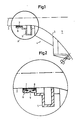
- the deflection unit 4 is partially seated on the picture tube neck 2 and partially abuts the picture tube cone 3.
- the coil body 5 of the deflection unit 4 has a tubular extension 6, which consists of thermoplastic material.
- the material is preferably an amorphous or partially crystalline thermoplastic.
- a ring 7 made of the same thermoplastic material as the extension 6 is attached to the picture tube neck 2, preferably by gluing.
- the ring 7 made of thermoplastic material is attached to the tube neck 2 by gluing.
- a cold-curing adhesive can be used, for example, or a double-sided adhesive tape.
- the deflection unit 4 is then pushed onto the picture tube in such a way that the tubular extension 6 of the bobbin 5 of the deflection unit 4 comes to rest on the ring 7.
- the deflection unit 4 is displaced in the longitudinal direction in a suitable adjusting device or rotated about its axis with respect to the picture tube until its optimal position is reached.
- the approach 6 are connected to the ring 7 by a short welding process, so that the deflection unit 4 is now fixed in its position with respect to the picture tube 1.
- the tubular extension 6 can be slotted in the direction of the tube axis.
- Fig. 2 which shows an enlarged section of the parts shown in circle A of Fig. 1, the adhesive layer 8 can also be seen, with which the ring 7 is attached to the picture tube neck 2 and a weld 9, with which the approach 6 and the ring 7 are interconnected.
- thermoplastic material from which the tubular extension 6 and the ring 7 are made can have a relatively high melting point because only a brief heating is required to weld the two parts, and this does not have any adverse effect on the picture tube.
- the welding at 9 of FIG. 2 can be achieved, for example, by pressing in a heated stamp at several points on the circumference.
- the ring 7 preferably has a surface which is curved in the direction of the tube axis or the tube neck. This can be seen particularly well from FIG. 2.
- the deflection unit can be moved in all directions, and after the two parts made of thermoplastic material have been welded, the picture tube and deflection unit can be taken out of the adjustment holder immediately, since the thermoplastic material quickly solidifies due to its high melting point. Nevertheless, there is no impermissibly high thermal effect on the picture tube, because only a brief and local heating is necessary and the welding takes place on the surface of the ring 7 facing away from the picture tube.
- thermoplastic material As a result of the relatively high melting point of the thermoplastic material, there is no fear of displacement of the deflection unit due to heating during the operation of the picture tube.
Landscapes
- Vessels, Lead-In Wires, Accessory Apparatuses For Cathode-Ray Tubes (AREA)
- Lining Or Joining Of Plastics Or The Like (AREA)
Applications Claiming Priority (2)
| Application Number | Priority Date | Filing Date | Title |
|---|---|---|---|
| DE19863621363 DE3621363A1 (de) | 1986-06-26 | 1986-06-26 | Bildroehre mit ablenkeinheit |
| DE3621363 | 1986-06-26 |
Publications (3)
| Publication Number | Publication Date |
|---|---|
| EP0250822A2 true EP0250822A2 (fr) | 1988-01-07 |
| EP0250822A3 EP0250822A3 (en) | 1990-04-04 |
| EP0250822B1 EP0250822B1 (fr) | 1993-08-04 |
Family
ID=6303718
Family Applications (1)
| Application Number | Title | Priority Date | Filing Date |
|---|---|---|---|
| EP87107142A Expired - Lifetime EP0250822B1 (fr) | 1986-06-26 | 1987-05-18 | Tube d'image avec unité de déviation |
Country Status (3)
| Country | Link |
|---|---|
| EP (1) | EP0250822B1 (fr) |
| JP (1) | JPS636733A (fr) |
| DE (2) | DE3621363A1 (fr) |
Cited By (1)
| Publication number | Priority date | Publication date | Assignee | Title |
|---|---|---|---|---|
| EP0521555A1 (fr) * | 1991-07-02 | 1993-01-07 | Koninklijke Philips Electronics N.V. | Tube-image muni d'un dispositif de deviation |
Family Cites Families (4)
| Publication number | Priority date | Publication date | Assignee | Title |
|---|---|---|---|---|
| US3663751A (en) * | 1970-04-16 | 1972-05-16 | Westinghouse Electric Corp | Potted elctrical component assembly |
| JPS5325232B2 (fr) * | 1972-04-10 | 1978-07-25 | ||
| JPS5093036A (fr) * | 1973-12-17 | 1975-07-24 | ||
| DE2650907A1 (de) * | 1976-11-06 | 1978-05-18 | Licentia Gmbh | Fernsehbildroehre mit einer daran befestigten ablenkeinheit |
-
1986
- 1986-06-26 DE DE19863621363 patent/DE3621363A1/de not_active Withdrawn
-
1987
- 1987-05-18 EP EP87107142A patent/EP0250822B1/fr not_active Expired - Lifetime
- 1987-05-18 DE DE8787107142T patent/DE3786847D1/de not_active Expired - Fee Related
- 1987-06-24 JP JP62155632A patent/JPS636733A/ja active Pending
Cited By (1)
| Publication number | Priority date | Publication date | Assignee | Title |
|---|---|---|---|---|
| EP0521555A1 (fr) * | 1991-07-02 | 1993-01-07 | Koninklijke Philips Electronics N.V. | Tube-image muni d'un dispositif de deviation |
Also Published As
| Publication number | Publication date |
|---|---|
| EP0250822B1 (fr) | 1993-08-04 |
| DE3786847D1 (de) | 1993-09-09 |
| EP0250822A3 (en) | 1990-04-04 |
| DE3621363A1 (de) | 1988-01-14 |
| JPS636733A (ja) | 1988-01-12 |
Similar Documents
| Publication | Publication Date | Title |
|---|---|---|
| DE3881120T2 (de) | Schaedelbohrer, versehen mit einer verbesserten befestigungshuelse. | |
| DE102007046376B4 (de) | Verschweißter Harzkörper und Verfahren zu dessen Herstellung | |
| DE4013162C2 (fr) | ||
| DE3812353C2 (fr) | ||
| EP0745779B1 (fr) | Procédé pour la fixation d'un palier en un matériau non soudable dans un trou d'une plaque support métallique | |
| EP0973014B1 (fr) | Appareil pour mesurer la position angulaire et son procédé de montage | |
| EP0250822B1 (fr) | Tube d'image avec unité de déviation | |
| DE2243492A1 (de) | Vorrichtung zum abschleifen der oberflaeche einer zwei roehrenfoermige teilstuecke verbindenden schweissnaht | |
| DE19819054B4 (de) | Verfahren und Vorrichtung zur Montage und Justierung von Bauteilen auf einer Befestigungsunterlage | |
| DE4437989A1 (de) | Verfahren zum Herstellen von Gelenkscheiben | |
| EP1357020B1 (fr) | Joint adhésif | |
| EP4339467B1 (fr) | Rivet aveugle, ainsi que système et procédé de fabrication de connexions de rivet aveugle étanches | |
| DE3727908A1 (de) | Schlauchverbindungsanordnung | |
| DE69202426T2 (de) | Ablenkeinheit und Herstellungsverfahren. | |
| DE3610313C2 (fr) | ||
| EP0170956A2 (fr) | Procédé pour fixer des clichés flexibles sur le cylindre de forme d'une machine à imprimer | |
| EP0611643A1 (fr) | Procédé pour la fabrication de joints soudés par joints ou par petites surfaces avec au moins deux couches en matière thermoplastique qui sont l'une sur l'autre ou qui s'approchent l'une de l'autre | |
| WO1995024355A1 (fr) | Tendeur et dispositif de stockage du fil et d'alimentation en fil | |
| DE2655960C3 (de) | Einrichtung zum Befestigen einer Ablenkeinheit am Kolben einer Fernsehbildröhre | |
| WO2003066273A1 (fr) | Dispositif de serrage et procede de soudure au laser de toles enduites | |
| DE2650907A1 (de) | Fernsehbildroehre mit einer daran befestigten ablenkeinheit | |
| DD266050A1 (de) | Reibschweissverbindung | |
| DE3742828C2 (de) | Verfahren zum Einsetzen und lagegenauen Befestigen von Lager- und Führungsteilen in einem Geräte-Chassis | |
| DD158076A1 (de) | Verfahren zum kleben von halbleiterchips auf traegerkoerpern | |
| DE102022134235A1 (de) | Stellvorrichtung, Positionier-Vorrichtung und Positionier-Anordnung |
Legal Events
| Date | Code | Title | Description |
|---|---|---|---|
| PUAI | Public reference made under article 153(3) epc to a published international application that has entered the european phase |
Free format text: ORIGINAL CODE: 0009012 |
|
| AK | Designated contracting states |
Kind code of ref document: A2 Designated state(s): DE FR GB IT NL |
|
| RAP1 | Party data changed (applicant data changed or rights of an application transferred) |
Owner name: NOKIA GRAETZ GESELLSCHAFT MIT BESCHRAENKTER HAFTUN |
|
| RAP1 | Party data changed (applicant data changed or rights of an application transferred) |
Owner name: NOKIA UNTERHALTUNGSELEKTRONIK (DEUTSCHLAND) GMBH |
|
| PUAL | Search report despatched |
Free format text: ORIGINAL CODE: 0009013 |
|
| AK | Designated contracting states |
Kind code of ref document: A3 Designated state(s): DE FR GB IT NL |
|
| RHK1 | Main classification (correction) |
Ipc: H01J 29/82 |
|
| 17P | Request for examination filed |
Effective date: 19900319 |
|
| RAP1 | Party data changed (applicant data changed or rights of an application transferred) |
Owner name: NOKIA (DEUTSCHLAND) GMBH |
|
| 17Q | First examination report despatched |
Effective date: 19920518 |
|
| GRAA | (expected) grant |
Free format text: ORIGINAL CODE: 0009210 |
|
| AK | Designated contracting states |
Kind code of ref document: B1 Designated state(s): DE FR GB IT NL |
|
| GBT | Gb: translation of ep patent filed (gb section 77(6)(a)/1977) |
Effective date: 19930803 |
|
| ITF | It: translation for a ep patent filed | ||
| REF | Corresponds to: |
Ref document number: 3786847 Country of ref document: DE Date of ref document: 19930909 |
|
| ET | Fr: translation filed | ||
| PGFP | Annual fee paid to national office [announced via postgrant information from national office to epo] |
Ref country code: GB Payment date: 19940511 Year of fee payment: 8 |
|
| PGFP | Annual fee paid to national office [announced via postgrant information from national office to epo] |
Ref country code: FR Payment date: 19940525 Year of fee payment: 8 |
|
| PGFP | Annual fee paid to national office [announced via postgrant information from national office to epo] |
Ref country code: NL Payment date: 19940531 Year of fee payment: 8 |
|
| PLBE | No opposition filed within time limit |
Free format text: ORIGINAL CODE: 0009261 |
|
| STAA | Information on the status of an ep patent application or granted ep patent |
Free format text: STATUS: NO OPPOSITION FILED WITHIN TIME LIMIT |
|
| PGFP | Annual fee paid to national office [announced via postgrant information from national office to epo] |
Ref country code: DE Payment date: 19940712 Year of fee payment: 8 |
|
| 26N | No opposition filed | ||
| PG25 | Lapsed in a contracting state [announced via postgrant information from national office to epo] |
Ref country code: GB Effective date: 19950518 |
|
| PG25 | Lapsed in a contracting state [announced via postgrant information from national office to epo] |
Ref country code: NL Effective date: 19951201 |
|
| GBPC | Gb: european patent ceased through non-payment of renewal fee |
Effective date: 19950518 |
|
| NLV4 | Nl: lapsed or anulled due to non-payment of the annual fee |
Effective date: 19951201 |
|
| PG25 | Lapsed in a contracting state [announced via postgrant information from national office to epo] |
Ref country code: DE Effective date: 19960201 |
|
| PG25 | Lapsed in a contracting state [announced via postgrant information from national office to epo] |
Ref country code: FR Effective date: 19960229 |
|
| REG | Reference to a national code |
Ref country code: FR Ref legal event code: ST |
|
| REG | Reference to a national code |
Ref country code: FR Ref legal event code: ST |
|
| PG25 | Lapsed in a contracting state [announced via postgrant information from national office to epo] |
Ref country code: IT Free format text: LAPSE BECAUSE OF NON-PAYMENT OF DUE FEES;WARNING: LAPSES OF ITALIAN PATENTS WITH EFFECTIVE DATE BEFORE 2007 MAY HAVE OCCURRED AT ANY TIME BEFORE 2007. THE CORRECT EFFECTIVE DATE MAY BE DIFFERENT FROM THE ONE RECORDED. Effective date: 20050518 |