EP0250936B1 - Verfahren zur Überwachung der Informationsübertragung auf durchgeschalteten vierdrähtigen Verbindungswegen, insbesondere semi-permanent durchgeschalteten Verbindungswegen in digitalen Zeitmultiplex-Vermittlungsstellen - Google Patents
Verfahren zur Überwachung der Informationsübertragung auf durchgeschalteten vierdrähtigen Verbindungswegen, insbesondere semi-permanent durchgeschalteten Verbindungswegen in digitalen Zeitmultiplex-Vermittlungsstellen Download PDFInfo
- Publication number
- EP0250936B1 EP0250936B1 EP87108196A EP87108196A EP0250936B1 EP 0250936 B1 EP0250936 B1 EP 0250936B1 EP 87108196 A EP87108196 A EP 87108196A EP 87108196 A EP87108196 A EP 87108196A EP 0250936 B1 EP0250936 B1 EP 0250936B1
- Authority
- EP
- European Patent Office
- Prior art keywords
- ltg
- liu
- parity
- line trunk
- channel information
- Prior art date
- Legal status (The legal status is an assumption and is not a legal conclusion. Google has not performed a legal analysis and makes no representation as to the accuracy of the status listed.)
- Expired - Lifetime
Links
- 230000005540 biological transmission Effects 0.000 title claims description 43
- 238000000034 method Methods 0.000 title claims description 18
- 238000012544 monitoring process Methods 0.000 claims description 19
- 238000012360 testing method Methods 0.000 claims description 13
- 238000012806 monitoring device Methods 0.000 claims description 11
- 230000002093 peripheral effect Effects 0.000 claims description 3
- 230000001960 triggered effect Effects 0.000 claims 1
- 230000015654 memory Effects 0.000 description 11
- 230000004807 localization Effects 0.000 description 4
- 239000013256 coordination polymer Substances 0.000 description 3
- 230000008878 coupling Effects 0.000 description 3
- 238000010168 coupling process Methods 0.000 description 3
- 238000005859 coupling reaction Methods 0.000 description 3
- 230000006870 function Effects 0.000 description 3
- 238000013016 damping Methods 0.000 description 1
- 238000001514 detection method Methods 0.000 description 1
- 239000011159 matrix material Substances 0.000 description 1
- 229920000682 polycarbomethylsilane Polymers 0.000 description 1
- 239000013589 supplement Substances 0.000 description 1
Images


Classifications
-
- H—ELECTRICITY
- H04—ELECTRIC COMMUNICATION TECHNIQUE
- H04Q—SELECTING
- H04Q11/00—Selecting arrangements for multiplex systems
- H04Q11/04—Selecting arrangements for multiplex systems for time-division multiplexing
Definitions
- the invention relates to a method for monitoring the transmission of information on through-connected four-wire connection paths, in particular semi-permanently connected connection paths in digital time-division multiplexing exchanges, in which connection groups divided into several units and a double switching network, over which each connection is routed in parallel twice, form peripheral functional blocks which are under the influence of a coordination processor.
- connection path throughput tests have only been carried out in connection with the establishment of the connection.
- Such a structure is known, for example, from TELCOM REPORT, Volume 4, supplement "Digitalvunssystem EWSD", 1981, pages 19 to 27.
- FR-A-2 233 780 shows a test arrangement for a time-division multiple switching device with duplicated sub-switching stages, in which the information to be supplied to the individual inputs of the switching device is provided with a parity bit for testing the interconnection, which also transmits via additional lines and memory locations via the switching device is determined and on the output side by means of a parity check whether the information and the associated parity bit have passed the coupling device in an unadulterated manner.
- This procedure is carried out in both duplicated parts of the coupling device independently of the procedure in the other part of the coupling device.
- FR-A-2 281 605 a method for checking the correct switching execution of a connection in digital data transmission systems between a specific input and between a specific output of a selector serving for the transmission of digital data is known.
- the check is carried out in such a way that a parity bit, which is transmitted together with the associated data, is changed to an incorrect parity bit before input to a specific input, in order to identify this input, so to speak, and that it is checked at the output corresponding to this input whether Data is received with an incorrect parity bit, which corresponds to a correct switch execution, or whether data with a correct parity bit occurs, which is an indication that it is not the data given to the input concerned and therefore the switch execution is incorrect. Any error found here is reported to a central controller, which is also responsible for the above-mentioned corruption of the parity bit.
- this object is achieved with a method which is characterized in that the channel information which arrives from the two switching power supplies to a line trunk group and in part is to be transmitted further via this in the outgoing transmission direction to a transmission link in the unit on the input side in this transmission direction are compared bit by bit so that the channel information arriving in the transmission direction from the transmission link to this line trunk group is provided with a parity bit in the unit on the input side in this transmission direction and after passing through all units of the same in the incoming transmission direction last unit in which the comparison the channel information coming from the switching network is subjected to a parity check that this channel information coming from the switching network in this unit of the connection group pe are also provided with a parity bit and, insofar as they are transmitted to the PCM link, are subjected to a parity check in the unit of the line group mentioned on the input side in the other transmission direction, and that, if this parity check signals the presence of an error, the parity bit with which the PCM channel information arriving from the transmission link is in
- the essence of the invention thus consists, firstly, in the monitoring of individual channels, further in that different monitoring principles are used in accordance with the different failure areas of the presumed digital time division multiplexing switching center, and finally in that measures are taken based on which, regardless of the location of the error, the error detection occurs a central office of the exchange can take place.
- the monitoring of control addresses relating to the connection can also be included in the connection-related monitoring, provided that a special structure of the connection groups is provided.
- a further embodiment of the invention relates to the handling of error messages which only lead to the emission of an interference signal when the error rate per unit of time has exceeded a predetermined limit value.
- the telecommunications network shown in FIG 1 shows two end exchanges EVST, to which a number of terminals in the form of telephone stations Tst and data terminals DE are connected. It also shows a further time-division multiplex exchange EWSD, which is connected to the end exchanges via transmission links ÜB and which functions as a transit exchange in the context of a leased line to be explained.
- This further time-division switching center EWSD like the end switching centers EVST, is divided into peripheral function blocks in the form of line groups LTG and a double switching network SN, which are under the control of a coordination processor CP.
- the line trunk groups LTG are in turn divided into several units, of which only those are shown, via which information to be transmitted between the terminals is routed and which are an interface unit LIU to the switching network SN, a group coupler GS and an interface unit for Transmission line ÜB acts.
- the connection path is continuously four-wire, i. H. both on the subscriber line to the EVST end office, in the end office, on the ÜB transmission link and in the EWSD transit office.
- the telephone stations Tst are connected to the end exchanges EVST via two-wire lines.
- FIG 1 also shows, a connection from a line trunk group LTG runs both over the switching network half SNO and over the switching network half SN1.
- connection group consists of several units, namely interfaces DIU and LIU and a group coupler GS. These units are under the control of a group processor GP, which in turn is influenced by the already mentioned coordination processor CP, the corresponding control paths running over the switching network SN (see also FIG 1).
- a device FAU for phase compensation is to be mentioned here, which contains a voice memory SM; in the case of the group coupler GS, this is a switching memory, which likewise consists of a voice memory SM and an associated hold memory CM, in which control addresses for the voice memory are stored, and also a damping device ATU.
- the interface unit LIU these are also the timing adjustment, i. H. the synchronization of the channel information on an internal clock serving voice memory SM.
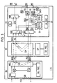
- the central part of the monitoring circuit required for performing the monitoring according to the invention is part of the interface unit LIU and is designated SV. It in turn consists of two function blocks SVSN and SVLTG, which, according to the concept on which the invention is based, for monitoring the switching network SN or the connection group LTG are responsible.
- the channel information which is sent from the two switching network halves SNO and SN1 to the interface LIU and is designated DATA in the FIGURE, is passed on to the transmission link ÜB via the group coupler GS and the interface unit DIU the monitoring circuit SVSN continuously compared bit by bit for agreement.
- the two data streams coming from the switching network SN only one is optionally transmitted depending on the switching position of the multiplexer MUX, which also forms part of the interface unit LIU.
- the channel information arriving in the transmission direction from the transmission link to the interface unit DIU is provided with a parity bit using a parity bit generator PG, which is also temporarily stored in the voice memory SM of this interface unit and then together with the channel information DATA, via the group coupler GS to the interface unit LIU, which means that all the units of the connection group LTG lying in the connection path have passed in one transmission direction.
- the above-mentioned monitoring device SVLTG carries out a parity check, which makes a statement about the connection path through the connection group LTG in the transmission direction from the input connection for the transmission connection for the transmission link PCMS to the switching network-side output connection.
- the channel information DATA coming from one or the other switching matrix half and provided with parity is transmitted via the group coupler GS to the interface unit DIU, so that all parts of the connecting group LTG lying in the connecting path also pass through in this opposite transmission direction are.
- a parity check is also carried out there with the help of a parity checker P.
- the parity bit which has been added to the information coming from the transmission link ÜB, is inverted with the aid of a device PC in contradiction to the actual parity of this information.
- the SVLTG monitoring device detects the presence of an error.
- the control addresses for the switching memory SM entered in the hold memory CM of the group coupler GS are also provided with a parity bit and are subjected to a parity check each time they are read cyclically. If an error is found here, the parity bit originally formed for the PCM channel information coming from the transmission link ÜB is inverted in accordance with the aforementioned procedure, so that in this case too, the parity check carried out by the monitoring device SVLTG in the interface unit LIU indicates the existence of a Error signaled.
- the channel errors for the switching network and for the connection group that are recorded centrally on the LIU module in this way are summed up separately for the two areas in channel-specific error counters.
- the counter readings of these counters are queried at certain time intervals and reported to the group processor GP, where a comparison with a predetermined quality threshold is carried out for each channel. If such a quality threshold is exceeded, a fault message is sent to the coordination processor CP.
- the coordination processor then initiates the establishment of this leased line via an alternative route.
- an error location is first carried out in the manner below and an error message is then sent to the coordination processor together with the result of the error location.
- the only thing that is checked for fault localization is whether the monitoring arrangement SVSN itself is the source of the fault, in that, as indicated in FIG. 3, the channel information to be passed on from the unit LU to the group coupler GS before and after inversion the associated parity bit is subjected to a parity check by the monitoring device SVSN before passing through further units of the line trunk group, with which a good / bad statement regarding this monitoring circuit is obtained.
- test loops (1) on the LIU module (2) are successively used for further fault localization, as can also be seen in FIG. 3. formed in the group coupler GS and (3a) and (3b) on the interface unit DIU.
- a test bit combination which is generated by a device TG belonging to the unit LIU, is sent via these test loops, and is sent via the switching network SN and from there to the unit LIU, where it is provided with a parity bit.
- the SVLTG monitoring device evaluates the test bit combinations coming back after the respective test loop has run through in the manner described.
Landscapes
- Engineering & Computer Science (AREA)
- Computer Networks & Wireless Communication (AREA)
- Monitoring And Testing Of Exchanges (AREA)
- Use Of Switch Circuits For Exchanges And Methods Of Control Of Multiplex Exchanges (AREA)
- Detection And Prevention Of Errors In Transmission (AREA)
- Time-Division Multiplex Systems (AREA)
- Data Exchanges In Wide-Area Networks (AREA)
Priority Applications (1)
| Application Number | Priority Date | Filing Date | Title |
|---|---|---|---|
| AT87108196T ATE69347T1 (de) | 1986-06-27 | 1987-06-05 | Verfahren zur ueberwachung der informationsuebertragung auf durchgeschalteten vierdraehtigen verbindungswegen, insbesondere semi-permanent durchgeschalteten verbindungswegen in digitalen zeitmultiplex-vermittlungsstellen. |
Applications Claiming Priority (2)
| Application Number | Priority Date | Filing Date | Title |
|---|---|---|---|
| DE3621531 | 1986-06-27 | ||
| DE3621531 | 1986-06-27 |
Publications (2)
| Publication Number | Publication Date |
|---|---|
| EP0250936A1 EP0250936A1 (de) | 1988-01-07 |
| EP0250936B1 true EP0250936B1 (de) | 1991-11-06 |
Family
ID=6303813
Family Applications (1)
| Application Number | Title | Priority Date | Filing Date |
|---|---|---|---|
| EP87108196A Expired - Lifetime EP0250936B1 (de) | 1986-06-27 | 1987-06-05 | Verfahren zur Überwachung der Informationsübertragung auf durchgeschalteten vierdrähtigen Verbindungswegen, insbesondere semi-permanent durchgeschalteten Verbindungswegen in digitalen Zeitmultiplex-Vermittlungsstellen |
Country Status (9)
| Country | Link |
|---|---|
| US (1) | US4821256A (pt) |
| EP (1) | EP0250936B1 (pt) |
| AR (1) | AR241357A1 (pt) |
| AT (1) | ATE69347T1 (pt) |
| BR (1) | BR8703222A (pt) |
| DE (1) | DE3774337D1 (pt) |
| DK (1) | DK166703B1 (pt) |
| FI (1) | FI87124C (pt) |
| PT (1) | PT85165B (pt) |
Families Citing this family (23)
| Publication number | Priority date | Publication date | Assignee | Title |
|---|---|---|---|---|
| US4964112A (en) * | 1988-06-01 | 1990-10-16 | Siemens Aktiengesellschaft | Method for monitoring the quality of a digital signal in sections of a data transmission circuit |
| DE59010400D1 (de) * | 1989-09-29 | 1996-08-08 | Siemens Ag | Schaltungsanordnung zur Prüfung von Teilen einer digitalen Zeitmultiplex-Fernmeldevermittlungsstelle, insbesondere Fernsprechvermittlungsstelle |
| DE4004956A1 (de) * | 1990-02-19 | 1991-08-22 | Philips Patentverwaltung | Koppelelement fuer ein asynchrones zeitvielfachuebermittlungssystem |
| EP0512143B1 (de) * | 1991-05-08 | 1996-09-25 | Siemens Aktiengesellschaft | Steuerungsanordnung für ein Breitbandvermittlungssystem |
| DE4128412C1 (pt) * | 1991-08-27 | 1992-12-10 | Siemens Ag, 8000 Muenchen, De | |
| DE59310324D1 (de) * | 1992-04-24 | 2003-02-13 | Siemens Ag | Verfahren zur Überwachung von virtuellen Verbindungen innerhalb eines digitalen Fernmeldenetzes |
| DE4218054C1 (de) * | 1992-06-01 | 1993-11-11 | Siemens Ag | Verfahren zur Mitlaufüberwachung und Bitfehlerreduktion für durchgeschaltete Verbindungen in digitalen Kommunikationssystemen |
| US5412709A (en) * | 1992-06-24 | 1995-05-02 | Charter Leasing Corporation | Digital telephone station line controller |
| JP3069440B2 (ja) * | 1992-06-30 | 2000-07-24 | 富士通株式会社 | 加入者線多重伝送システムの集中監視方式 |
| ATE140115T1 (de) * | 1992-08-25 | 1996-07-15 | Siemens Ag | Koordinierungssystem zur koordinierung von verbindungsanforderungen |
| WO1994005121A1 (de) * | 1992-08-25 | 1994-03-03 | Siemens Aktiengesellschaft | Call-processing-system zur steuerung von verbindungen in einem vermittlungssystem |
| ES2173079T3 (es) * | 1992-11-20 | 2002-10-16 | Siemens Ag | Procedimiento para la supervision de conexiones telefonicas existentes, especialmente conexiones telefonicas conmutadas de forma permanente. |
| DE4317367C1 (de) * | 1993-05-25 | 1994-08-25 | Siemens Ag | Koppelnetz für eine digitale Zeitmultiplex-Fernsprechvermittlungsstelle |
| SE515259C2 (sv) * | 1995-04-24 | 2001-07-09 | Ericsson Telefon Ab L M | Metod att styra förbindelser i ett telekommunikationssystem |
| SE505322C2 (sv) | 1995-12-29 | 1997-08-04 | Ericsson Telefon Ab L M | Rutinkontroll av paritetsunderhåll |
| US5959970A (en) * | 1996-05-29 | 1999-09-28 | Lucent Technologies Inc. | Circuit pack sparing arrangement |
| TW564317B (en) * | 1999-04-28 | 2003-12-01 | Matsushita Electric Industrial Co Ltd | Semiconductor integrated circuit and the checking method |
| DE10246105A1 (de) * | 2002-10-02 | 2004-04-15 | Siemens Ag | Schaltungsanordnung zur Verbindung von mehreren Amtsverbindungsleitungen über PCM-Strecken (Datenübertragungsstrecke für pulse code modulierte Signale) mit einem amtsinteren Koppelnetz, zur Verwendung in einer vermittlungstechnischen Anlage |
| US8621773B2 (en) | 2003-06-13 | 2014-01-07 | Battenfeld Technologies, Inc. | Shooting rests for supporting firearms |
| US10514225B2 (en) | 2018-01-17 | 2019-12-24 | Battenfeld Technologies, Inc. | Firearm shooting rest |
| US10782085B2 (en) | 2019-02-15 | 2020-09-22 | Aob Products Company | Recoil-reducing firearm shooting rest having tank |
| US11841108B2 (en) | 2019-12-17 | 2023-12-12 | Aob Products Company | Multi-legged equipment support having leg angle adjustment |
| US12004658B2 (en) | 2021-04-15 | 2024-06-11 | Aob Products Company | Shooting rest chair |
Family Cites Families (10)
| Publication number | Priority date | Publication date | Assignee | Title |
|---|---|---|---|---|
| US3471830A (en) * | 1964-04-01 | 1969-10-07 | Bell Telephone Labor Inc | Error control system |
| FR2233780B1 (pt) * | 1973-06-13 | 1977-05-06 | Materiel Telephonique | |
| GB1504897A (en) * | 1974-08-09 | 1978-03-22 | Ericsson L M Pty Ltd | Method for through connection check in digital data systems |
| FR2305908A1 (fr) * | 1975-03-27 | 1976-10-22 | Materiel Telephonique | Reseau de commutation entre des voies de communication multiplexees dans le temps |
| US4261054A (en) * | 1977-12-15 | 1981-04-07 | Harris Corporation | Real-time adaptive power control in satellite communications systems |
| US4149038A (en) * | 1978-05-15 | 1979-04-10 | Wescom Switching, Inc. | Method and apparatus for fault detection in PCM muliplexed system |
| ZA804384B (en) * | 1979-08-10 | 1981-07-29 | Plessey Co Ltd | Digital telecommunications switching network with in-built fault identification |
| JPS57385A (en) * | 1980-06-02 | 1982-01-05 | Toshiba Corp | Delivery measuring device for pump or fan |
| US4345324A (en) * | 1980-07-09 | 1982-08-17 | Christian Rovsing A/S | Process and system for error detection in a computer-controlled telephone exchange |
| SE431143B (sv) * | 1982-05-26 | 1984-01-16 | Ellemtel Utvecklings Ab | Sett och anordning for genomkopplingskontroll i ett digitalt telekommunikationsnet av tidsmultiplex typ |
-
1987
- 1987-05-26 AR AR87307651A patent/AR241357A1/es active
- 1987-06-05 DE DE8787108196T patent/DE3774337D1/de not_active Expired - Lifetime
- 1987-06-05 AT AT87108196T patent/ATE69347T1/de not_active IP Right Cessation
- 1987-06-05 EP EP87108196A patent/EP0250936B1/de not_active Expired - Lifetime
- 1987-06-25 PT PT85165A patent/PT85165B/pt not_active IP Right Cessation
- 1987-06-25 US US07/067,065 patent/US4821256A/en not_active Expired - Lifetime
- 1987-06-26 FI FI872832A patent/FI87124C/fi not_active IP Right Cessation
- 1987-06-26 BR BR8703222A patent/BR8703222A/pt not_active IP Right Cessation
- 1987-06-26 DK DK327387A patent/DK166703B1/da not_active IP Right Cessation
Also Published As
| Publication number | Publication date |
|---|---|
| PT85165A (pt) | 1988-07-01 |
| BR8703222A (pt) | 1988-03-15 |
| DK166703B1 (da) | 1993-06-28 |
| DK327387D0 (da) | 1987-06-26 |
| PT85165B (pt) | 1993-06-30 |
| DE3774337D1 (de) | 1991-12-12 |
| FI872832A0 (fi) | 1987-06-26 |
| ATE69347T1 (de) | 1991-11-15 |
| AR241357A1 (es) | 1992-05-29 |
| US4821256A (en) | 1989-04-11 |
| EP0250936A1 (de) | 1988-01-07 |
| FI872832L (fi) | 1987-12-28 |
| DK327387A (da) | 1987-12-28 |
| FI87124B (fi) | 1992-08-14 |
| FI87124C (fi) | 1992-11-25 |
Similar Documents
| Publication | Publication Date | Title |
|---|---|---|
| EP0250936A1 (de) | Verfahren zur Überwachung der Informationsübertragung auf durchgeschalteten vierdrähtigen Verbindungswegen, insbesondere semi-permanent durchgeschalteten Verbindungswegen in digitalen Zeitmultiplex-Vermittlungsstellen | |
| DE69212544T2 (de) | Zwischeneinheit für Protokoll-Analysator | |
| DE4411479A1 (de) | Digitaler elektronischer Zwischenverteiler für Nachrichten- und Datenübertragungssysteme | |
| EP0111832B1 (de) | Schaltungsanordnung zur Fehlerortung bei einem digitalen Fernmelde-Teilnehmeranschluss | |
| EP0448734B1 (de) | Schaltungsanordnung für die Routineprüfung einer Schnittstelle zwischen Anschlussgruppen und dem Koppelnetz eines PCM-Fernmeldevermittlungssystems | |
| DE69523803T2 (de) | Schnittstelle für Telekommunikationsteilnehmer | |
| DE19506961C1 (de) | Verfahren zum Anschluß von Access-Networks mit V5.2-Schnittstellen an Kommunikationssysteme mit nichtredundanten peripheren Einrichtungen | |
| EP0163288B1 (de) | Verfahren zur Durchschalteprüfung eines Raummultiplex-Koppelnetzes | |
| EP1104636A2 (de) | Verfahren und einrichtung zur überprüfung der funktionsfähigkeit einer vermittlungsstelle | |
| DE3003282C2 (de) | Verfahren zur Prüfung von Satzschaltungen einer Vermittlungsstelle eines digitalen Zeitmultiplex-Fernmeldenetzes, sowie gegebenenfalls der an die Vermittlungsstelle angeschlossenen Leitungen | |
| DE2304923C3 (de) | Verfahren zur Prüfung von Vierdrahtverbindungen zwischen zwei miteinander zu verbindenden Schaltstellen eines Fernmeldenetze? | |
| DE3821871C2 (pt) | ||
| DE2316478C3 (de) | Verfahren zur Prüfung und Aufrechterhaltung der Funktionsfähigkeit eines Zeitmultiplex-Vermittlungsnetzes | |
| EP0598931B1 (de) | Verfahren zur Überwachung bestehender Fernsprechverbindungen, insbesondere permanent geschalteter Fernsprechverbindungen | |
| DE2819646C2 (de) | Schaltungsanordnung zur Prüfung von Koppelfeldwegen in zeitmultiplexen Fernmelde-, insbesondere Fernsprechvermittlungsanlagen | |
| DE2849348C2 (pt) | ||
| DE3513181A1 (de) | Schaltungsanordnung fuer fernmeldevermittlungsanlagen, insbesondere fernsprechvermittlungsanlagen, mit einrichtungen zur funktionsfaehigkeitspruefung durchgeschalteter verbindungen | |
| DE3932700C2 (de) | Verfahren zur Durchschalteprüfung eines Koppelnetzes | |
| EP0272513B1 (de) | Verfahren zur Prüfung eines Schnittstellenbausteins | |
| DE3235730C2 (pt) | ||
| EP1238564B1 (de) | Datenübertragungsschnittstelle für ein koppelnetzwerk sowie dazugehöriges testverfahren | |
| DE2945032C2 (de) | Verfahren zur Prüfung der Sendeeinrichtung für Wahlinformationen von Verbindungsleitungs- Übertragungen | |
| DE19711321C1 (de) | Teilnehmeranschlußkonzentrator | |
| EP1210813B1 (de) | Lokalisierung eines gestörten streckenabschnitts in einer aktiven langzeitverbindung | |
| DE10246347B4 (de) | Testschaltungsanordnung, Testsystem und Verfahren zum Testen eines Endgeräteanschlusses |
Legal Events
| Date | Code | Title | Description |
|---|---|---|---|
| PUAI | Public reference made under article 153(3) epc to a published international application that has entered the european phase |
Free format text: ORIGINAL CODE: 0009012 |
|
| AK | Designated contracting states |
Kind code of ref document: A1 Designated state(s): AT BE CH DE FR GB IT LI NL SE |
|
| 17P | Request for examination filed |
Effective date: 19880325 |
|
| 17Q | First examination report despatched |
Effective date: 19900226 |
|
| GRAA | (expected) grant |
Free format text: ORIGINAL CODE: 0009210 |
|
| AK | Designated contracting states |
Kind code of ref document: B1 Designated state(s): AT BE CH DE FR GB IT LI NL SE |
|
| REF | Corresponds to: |
Ref document number: 69347 Country of ref document: AT Date of ref document: 19911115 Kind code of ref document: T |
|
| REF | Corresponds to: |
Ref document number: 3774337 Country of ref document: DE Date of ref document: 19911212 |
|
| ET | Fr: translation filed | ||
| ITF | It: translation for a ep patent filed | ||
| GBT | Gb: translation of ep patent filed (gb section 77(6)(a)/1977) | ||
| PLBE | No opposition filed within time limit |
Free format text: ORIGINAL CODE: 0009261 |
|
| STAA | Information on the status of an ep patent application or granted ep patent |
Free format text: STATUS: NO OPPOSITION FILED WITHIN TIME LIMIT |
|
| 26N | No opposition filed | ||
| PGFP | Annual fee paid to national office [announced via postgrant information from national office to epo] |
Ref country code: GB Payment date: 19930518 Year of fee payment: 7 |
|
| PGFP | Annual fee paid to national office [announced via postgrant information from national office to epo] |
Ref country code: AT Payment date: 19930519 Year of fee payment: 7 |
|
| PGFP | Annual fee paid to national office [announced via postgrant information from national office to epo] |
Ref country code: BE Payment date: 19930608 Year of fee payment: 7 |
|
| PGFP | Annual fee paid to national office [announced via postgrant information from national office to epo] |
Ref country code: NL Payment date: 19930630 Year of fee payment: 7 |
|
| PG25 | Lapsed in a contracting state [announced via postgrant information from national office to epo] |
Ref country code: GB Effective date: 19940605 Ref country code: AT Effective date: 19940605 |
|
| PG25 | Lapsed in a contracting state [announced via postgrant information from national office to epo] |
Ref country code: BE Effective date: 19940630 |
|
| BERE | Be: lapsed |
Owner name: SIEMENS A.G. Effective date: 19940630 |
|
| PG25 | Lapsed in a contracting state [announced via postgrant information from national office to epo] |
Ref country code: NL Effective date: 19950101 |
|
| EAL | Se: european patent in force in sweden |
Ref document number: 87108196.4 |
|
| GBPC | Gb: european patent ceased through non-payment of renewal fee |
Effective date: 19940605 |
|
| NLV4 | Nl: lapsed or anulled due to non-payment of the annual fee | ||
| PGFP | Annual fee paid to national office [announced via postgrant information from national office to epo] |
Ref country code: CH Payment date: 19950913 Year of fee payment: 9 |
|
| PGFP | Annual fee paid to national office [announced via postgrant information from national office to epo] |
Ref country code: SE Payment date: 19960619 Year of fee payment: 10 |
|
| PGFP | Annual fee paid to national office [announced via postgrant information from national office to epo] |
Ref country code: FR Payment date: 19960625 Year of fee payment: 10 |
|
| PG25 | Lapsed in a contracting state [announced via postgrant information from national office to epo] |
Ref country code: LI Effective date: 19960630 Ref country code: CH Effective date: 19960630 |
|
| REG | Reference to a national code |
Ref country code: CH Ref legal event code: PL |
|
| PG25 | Lapsed in a contracting state [announced via postgrant information from national office to epo] |
Ref country code: SE Effective date: 19970606 |
|
| PG25 | Lapsed in a contracting state [announced via postgrant information from national office to epo] |
Ref country code: FR Free format text: LAPSE BECAUSE OF NON-PAYMENT OF DUE FEES Effective date: 19980227 |
|
| EUG | Se: european patent has lapsed |
Ref document number: 87108196.4 |
|
| REG | Reference to a national code |
Ref country code: FR Ref legal event code: ST |
|
| REG | Reference to a national code |
Ref country code: FR Ref legal event code: ST |
|
| PGFP | Annual fee paid to national office [announced via postgrant information from national office to epo] |
Ref country code: DE Payment date: 20010823 Year of fee payment: 15 |
|
| PG25 | Lapsed in a contracting state [announced via postgrant information from national office to epo] |
Ref country code: DE Free format text: LAPSE BECAUSE OF NON-PAYMENT OF DUE FEES Effective date: 20030101 |
|
| PG25 | Lapsed in a contracting state [announced via postgrant information from national office to epo] |
Ref country code: IT Free format text: LAPSE BECAUSE OF NON-PAYMENT OF DUE FEES Effective date: 20050605 |