EP0250945B1 - Grosse Vase für Pflanzen - Google Patents
Grosse Vase für Pflanzen Download PDFInfo
- Publication number
- EP0250945B1 EP0250945B1 EP87108279A EP87108279A EP0250945B1 EP 0250945 B1 EP0250945 B1 EP 0250945B1 EP 87108279 A EP87108279 A EP 87108279A EP 87108279 A EP87108279 A EP 87108279A EP 0250945 B1 EP0250945 B1 EP 0250945B1
- Authority
- EP
- European Patent Office
- Prior art keywords
- containment element
- pot
- spacer
- containment
- stem
- Prior art date
- Legal status (The legal status is an assumption and is not a legal conclusion. Google has not performed a legal analysis and makes no representation as to the accuracy of the status listed.)
- Expired
Links
- 125000006850 spacer group Chemical group 0.000 claims abstract description 29
- XLYOFNOQVPJJNP-UHFFFAOYSA-N water Substances O XLYOFNOQVPJJNP-UHFFFAOYSA-N 0.000 claims abstract description 20
- 239000002689 soil Substances 0.000 claims abstract description 10
- 238000001914 filtration Methods 0.000 claims abstract description 6
- 238000005273 aeration Methods 0.000 claims abstract description 5
- 230000000284 resting effect Effects 0.000 claims description 8
- 239000004744 fabric Substances 0.000 claims description 2
- 210000005069 ears Anatomy 0.000 claims 1
- 230000014759 maintenance of location Effects 0.000 claims 1
- 238000003860 storage Methods 0.000 abstract description 2
- 238000005034 decoration Methods 0.000 abstract 1
- 238000005266 casting Methods 0.000 description 2
- 238000004519 manufacturing process Methods 0.000 description 2
- 239000000463 material Substances 0.000 description 2
- 230000004308 accommodation Effects 0.000 description 1
- 238000009825 accumulation Methods 0.000 description 1
- 238000001035 drying Methods 0.000 description 1
- 238000003780 insertion Methods 0.000 description 1
- 230000037431 insertion Effects 0.000 description 1
- 238000003973 irrigation Methods 0.000 description 1
- 230000002262 irrigation Effects 0.000 description 1
- 230000005923 long-lasting effect Effects 0.000 description 1
- 238000012986 modification Methods 0.000 description 1
- 230000004048 modification Effects 0.000 description 1
- 238000001556 precipitation Methods 0.000 description 1
Images
Classifications
-
- A—HUMAN NECESSITIES
- A01—AGRICULTURE; FORESTRY; ANIMAL HUSBANDRY; HUNTING; TRAPPING; FISHING
- A01G—HORTICULTURE; CULTIVATION OF VEGETABLES, FLOWERS, RICE, FRUIT, VINES, HOPS OR SEAWEED; FORESTRY; WATERING
- A01G9/00—Cultivation in receptacles, forcing-frames or greenhouses; Edging for beds, lawn or the like
- A01G9/02—Receptacles, e.g. flower-pots or boxes; Glasses for cultivating flowers
-
- A—HUMAN NECESSITIES
- A47—FURNITURE; DOMESTIC ARTICLES OR APPLIANCES; COFFEE MILLS; SPICE MILLS; SUCTION CLEANERS IN GENERAL
- A47G—HOUSEHOLD OR TABLE EQUIPMENT
- A47G7/00—Flower holders or the like
- A47G7/02—Devices for supporting flower-pots or cut flowers
- A47G7/06—Flower vases
Definitions
- the present invention relates to a large pot for plants.
- the first disadvantage resides in the fact that they are difficult to transport and to position, so that there is a constant trend towards the use of pots having the smallest possible dimensions so as to simultaneously contain weight.
- Another existing disadvantage is due to the poor aesthetics of the monolithic prefabricated pot, which makes troublesome its use and its harmonization with the locations where it is installed.
- prior art document AT-B-316 914 shows a pot which is comprised of separate smaller parts which are assembled to thereby form the larger pot.
- the pot according to this document suffers the disadvantages of providing unsatisfactory support for the assembled pot, as well as offering a poor aesthetic appearance which compromises its' use and harmonization with its surroundings.
- the aim of the present invention is therefore to eliminate the above disadvantages of the prior art, by providing a large pot for flowers and/or plants, easy to transport and to install.
- an important object consists of providing a large pot which, further to the preceding features, is optimally installable also on uneven ground, which is thus not perfectly planar.
- Still another object is to provide a large pot which allows optimum aeration of the soil contained therein.
- Another important object is to provide a large pot which simultaneously allows accumulation of water, forming a reserve for plants, and draining thereof in case of excessive amounts, for example due to remarkable or long-lasting atmospheric precipitations.
- Not least object is to provide a large pot which has limited costs, while allowing manufacture with usual known devices and machines.
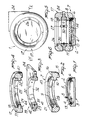
- the pot indicated by the reference numeral 1, comprises a base 2, in the shape of a cylinder and having a planar surface 3 for resting on the ground and a central recess 4 defining an upper annular planar shoulder 5.
- level adjusting means for adjusting the horizontal arrangement of a first containment element 7 arrangeable above the base 2.
- This level adjustment means comprises first bolts 8, the heads whereof projects in the direction of the overlying first containment element 7.
- the latter has an essentially annular shape with a T-shaped transverse cross section defining a first stem 9 projecting inside the element 7 and having such a length as to define, when its lower lateral surface 10 rests on the underlying bolts 8, an interspace 11 suitable to allow both passage of air from outside to the interior of the vase and outflow of water, contained in the recess 4, from the vase if the water rises above the annular shoulder 5 of the base 2.
- a step 13 is furthermore provided, for supporting a water filtering means consisting of a circular drilled tray 14, having the same diameter as the base 2 at the step 13.
- the first containment element 7 furthermore comprises a first, lower, rounded portion 15 facing the underlying base 2 and a second, upper, planar portion 16.
- the vase 1 also comprises a second containment element 17, equal to the first containment element 7, both being obtainable from the same casting.
- the second containment element 17 has an annular shape with a second stem 18 protruding inside the vase, the second element 17 being coupled to the first element 7 by arranging them mutually juxtaposed. Furthermore, the second containment element 17 has a lower planar portion 40 corresponding to portion 16 and an upper rounded portion 39 corresponding to portion 15.
- a variable height spacer 9 may be interposed, including a first ring 20 resting on the upper lateral surface 21 of the first stem 9 and at the corresponding lower lateral surface 22 of the second stem 18, the radial thickness of the ring being equal to the length of the stems.
- An annular tab 23 projects radially and externally to the ring 20 so as to extend between the second planar portion 16 of the first containment element 7 and the corresponding portion 40 of the second containment element 17.
- the tab 23 defines, together with the ring 20, two steps 41, 42, cooperating with respective countershaped steps 43, 44 formed by the planar portions 16 and 40 with the stems 9 and 18 of the containment elements, so as to center these elements 7 and 17 and prevent them from getting offset.
- the annular tab presents a projecting portion 24 extending approximately along one quarter of the circumference of the ring 20 and having a substantially triangular shape.
- the upper lateral surface 25 of the second stem 18 may support a second ring 26 having a radial thickness equal to the radial extension of the lateral surface 21.
- the containment elements and the spacer 19 cooperate with means for improving their mutual centering, consisting of a plurality of brackets 27 arranged approximately parallel to the central axis of the vase 1 and having such a length as to span the entire height of the innerwall 32 of the ring 20 and partially the lateral walls 28 and 29 respectively of the stems 9 and 18.
- Each bracket 27 is drilled, and a locking means, comprising second bolts 30 associable with suitable second bushes 31, embedded in the inner wall 32 of the ring, 20 is associable therewith.
- Manufacture and use of the large pot for plants is therefore as follows: after forming the various components individually, with the first and second containment elements requiring a same mold, they may be transported, unassembled, to the location of use.
- first bolts 8 allow, by screwing or unscrewing them, for example before positioning of the first element 7, to create resting points for the latter, which thus may arrange itself perfectly horizontal, regardless of any unevenness of the ground.
- the insertion of the tray 14 allows optimum draining of the water in the recess 4, which water can flow out of the vase through the interspace 11.
- brackets 27 allow optimum centering of the containment elements as well as the spacer 19.
- the large pot for plants according to the invention achieves the intended aim and objects, being easy transportable and installable even on uneven ground, and simultaneously allowing storage of reserve water for the plants, optimum aeration of the soil contained therein, and draining of excess water from its interior.
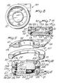
- figs. 7-10 illustrate a second embodiment of a pot 101, also comprising a base 102 having a recess 104 defining an Upper planar annular shoulder 105, and supporting a tray 114 together with a first containment element 107 by virtue of the presence of the first bolts 108 accommodated in bushes 106 provided in the shoulder 105.
- the dimensions of the base 102 and of the first containment element allow to define an interspace 111 therebetween, and the base 102 has a planar surface 103 for resting on the ground.
- the first containment 107 comprises a first rounded portion 115 and a first stem 109 which defines a lower lateral surface 110 for resting on the bolts 108.
- the second containment element 117 comprises a second rounded portion 139 and a second stem 118 which defines an upper stem surface 125.
- This second embodiment differs from the preceding one for the containment elements 107 and 117 are L-shaped in cross-section and have their respective facing portions 121 and 122 planar and level with the respective stems 109 and 118.
- An annular tab 123 extending between the facing portions 121 and 122, radially projects from the first ring 120 defining the spacer 119, this first ring projecting toward the interior of the pot and being provided, at its end opposite to the tab 123 with a circular shoulder 132 projecting towards the second containment element 117.
- a second ring 126 is also associated with the latter.
- a first seat 133 is defined for the accommodation, for example, of a main plant as well as a second seat 134, concentric to the previous one, for example for accomodating small flowers and other plants.
- the function of the tray 114 remains that of preventing escape of the soil from recess 104, allowing, at the same time, outflow of water.
- Fig. 11 illustrates a third embodiment of a pot 201 which is provided, at the base 202, with a pot moving means, comprising a ring-bolt 235 radially associated with the base below the first portion 215 of the first containment element 207.
- the pot according to the third embodiment comprises a first containment element 207 having a first rounded portion 215 and a first stem 209 defining a lower lateral surface 210 which rests upon leveling bolt means 208 accommodated in first bushes 206 provided in an upper planar shoulder 205 of the base 202.
- the second containment element 217 has a second rounded portion 239 and a second stem 218, and the base 202 has a lower planar surface 203.
- the spacer 219 is constituted by an annular cylindrical ring which is interposed, when the pot is assembled, between a lower facing portion 222 of the second containment element 217 and an upper facing portion 221 of the first containment element 207.
- the water filtering means comprises a fabric sheet 214 intended to prevent passage of the soil to the underlying recess 204 but such as to allow passage of water 212 therethrough.
- the brackets 227 are furthermore rigidly associated, by means of suitable second bolts 230a and 230b, with suitable second bushes 231a and 231b provided at the lateral walls 228 and 229 of the first containment element 207 and of the second containment element 217.
- Each bracket 227 furthermore presents an ear 236 having a hole allowing, for example through a suitable hook 237, partial transfer of the first and second containment elements and of the spacer.
Landscapes
- Life Sciences & Earth Sciences (AREA)
- Environmental Sciences (AREA)
- Cultivation Receptacles Or Flower-Pots, Or Pots For Seedlings (AREA)
Claims (8)
- Großer Topf für Pflanzen, mit einem zwischen einem ersten Behälterelement (7, 107, 207) und einem zweiten Behälterelement (17, 117, 217) einsetzbaren Abstandselement (19, 119, 219), einer das erste Behälterelement (7, 107, 207) halternden Basis (2, 102, 202), sowie Niveauregulierungseinrichtungen (8, 108, 208) zum horizontalen Ausrichten des Topfes gegenüber einer nicht horizontalen Untergrundoberfläche des Topfes, dadurch gekennzeichnet, daß die Basis (2, 102, 202) eine untere ebene Oberfläche (3, 103, 203) aufweist, die auf der Untergrundoberfläche des Topfes aufliegt, die Niveauregulierungsmittel (8, 108, 208) zwischen der Basis (2, 102, 202) und dem ersten Behälterelement (7, 107, 207) angeordnet sind, so daß das erste Behälterelement (7, 107, 207) mit dem Abstandselement (19, 119, 219) und dem zugeordneten zweiten Behälterelement (17, 117, 217) eine horizontale Ausrichtung erreichen kann, während die ebene Oberfläche (3, 103, 203) der Basis (2, 102, 202) mit der Untergrundoberfläche des Topfes ausgerichtet bleibt, und daß der Topf weiterhin Wasserfiltermittel (14, 114, 214) aufweist, die in einer Ausnehmung (4, 104, 204) der Basis (2, 102, 202) zwischen der Basis (2, 102, 202), und dem ersten Behälterelement (7, 107, 207) vorgesehen sind.
- Topf nach Anspruch 1, dadurch gekennzeichnet, daß die Basis (2, 102, 202) Zylinderform mit einer zentralen Ausnehmung (4, 104, 204) aufweist, die eine obere ebene Schulter (5, 105, 205) bildet, in der erste Buchsen (6, 106, 206) eingebettet sind, daß die Niveauregulierungsmittel erste Bolzen (8, 108, 208) umfassen, die in den ersten Buchsen (6, 106, 206) aufgenommen sind, daß das erste Behälterelement (7, 107, 207) Ringform aufweist und einen ersten nach innen vorspringenden Schaft (9, 109, 209) und einen ersten nach unten vorspringenden abgerundeten Abschnitt (15, 115, 215) aufweist, eine untere seitliche Oberfläche (10, 110, 210) an dem nach innen vorspringenden ersten Schaft (9, 109, 209) des ersten Behälterelements (7, 107, 207) gebildet ist, die untere seitliche Oberfläche (10, 110, 210) auf den ersten Bolzen (8, 108, 208) ruht, wenn das erste Behälterelement (7, 107, 207) auf die Basis (2, 102, 202) gelegt und von dieser gehaltert wird, die zylindrisch geformte Basis (2, 102, 202) und das ringförmig ausgebildete erste Behälterelement (7, 107, 207) derart aufeinander abgestimmte Abmessungen aufweisen, daß ein Zwischenraum (11, 111, 211) zwischen dem ersten Behälterelement (7, 107, 207) und der Basis (2, 102, 202) gebildet ist, wenn die untere seitliche Oberfläche (10, 110, 210) auf den ersten Bolzen (8, 108, 208) liegt, wobei der Zwischenraum (11, 111, 211) gleichzeitig als ein Entladedurchgang für überschüssiges Wasser und als Belüftungsdurchgang für in dem Topf enthaltene Erde dient.
- Topf nach Anspruch 2, dadurch gekennzeichnet, daß das erste Behälterelement (7) weiterhin einen sich nach oben erstreckenden und zusammen mit dem nach innen ragenden ersten Schaft (9) eine Stufe (43) des ersten Behälterelements bildenden ebenen Abschnitt (16) umfaßt, das Abstandselement (19) Ringform mit einem T-förmigen Querschnitt, bestehend aus einem ersten Ring (20) und einem äußeren ringförmigen Ansatz (23) aufweist, der erste Ring (20) und der äußere ringförmige Ansatz (23) eine untere Abstandsstufe (21) und eine obere Abstandsstufe (42) bilden, das zweite Behälterelement (17) Ringform aufweist und einen zweiten nach innen ragenden Schaft (18), einen zweiten nach oben vorspringenden abgerundeten Abschnitt (39) und einem zweiten nach unten vorspringenden ebenen Abschnitt (40) aufweist, eine untere Stufe (44) des zweiten Behälterelements von dem nach innen vorspringenden zweiten Schaft (18) und dem nach unten vorspringenen zweiten ebenen Abschnitt (40) gebildet wird, das erste Behälterelement (7), das Abstandselement (19) und das zweite Behälterelement (17) jeweils derartige gegenseitige Abmessungen aufweisen, daß bei zusammengesetztem Topf die untere Stufe (44) des zweiten Behälterelements in der oberen Abstandsstufe (42) untergebracht ist, die obere Schulter (43) des ersten Behälterelements in der unteren Abstandsstufe (41) untergebracht ist, und daß dadurch eine wechselseitig Zentrierung des ersten Behälterelements (7), des Abstandselements (19) und des zweiten Behälterelements (17) erreicht wird.
- Topf nach Anspruch 3, dadurch gekennzeichnet, daß der nach innen vorspringende zweite Schaft (18) des zweiten Behälterelements eine obere Schaftoberfläche (25) bildet, der Topf weiterhin einen zweiten Ring (26) aufweist, der auf der oberen Schaftoberfläche (25) aufruht, und Klammern (27) an der Innenwand (32) des ersten Rings mit Hilfe von zweiten Bolzen (30) festgeschraubt sind, die in zweiten Buchsen (31) angeordnet sind, wobei die Klammern (27) eine Länge aufweisen, die die gesamte Höhe der Innenwand (32) des ersten Rings und teilweise die inneren Seitenwände (28, 29) des ersten Schafts (29) und des zweiten Schafts (18) überspannt, zur Schaffung einer zusätzlichen Zentrierung und Positionssicherung des ersten Behälterelements (7), des Abstandselements (19) und des zweiten Behälterelements (17).
- Topf nach Anspruch 2, dadurch gekennzeichnet, daß das erste Behälterelement (107) einen L-förmigen Querschnitt mit einem oberen Stirnabschnitt (122) aufweist, das zweite Behälterelement (17) einen L-förmigen Querschnitt mit einem zweiten abgerundeten Abschnitt (139) und einem zweiten Schaft (118) aufweist, der einen unteren Stirnabschnitt (122) bildet, das Abstandselement (119) einen ersten Ring (120) und einen äußeren ringförmigen Absatz (123) aufweist, der sich zwischen dem oberen Stirnabschnitt (121) und dem unteren Stirnabschnitt (122) erstreckt, wenn das erste Behälterelement (107), das Abstandselement (119) und das zweite Behälterelement (117) zur Bildung des Topfes zusammengesetzt sind, der erste Ring (120) des Abstandselementes (119) nach innen in Richtung auf das Topfinnere vorspringt und weiterhin mit einer kreisförmigen Schulter (132) versehen ist, die nach oben in das Topfinnere vorspringt, ein erster innerer kreisförmiger Sitz (133) und ein zweiter äußerer ringförmiger Sitz (134) von dem ersten Ring (120) des Abstandselementes und der kreisförmigen Schulter (132) des Abstandselements (119) gebildet werden, und der Topf weiterhin einen zweiten Ring (126) umfaßt, der auf einer oberen Schaftoberfläche (125) des zweiten Schafts (118) des zweiten Behälterelements (117) aufruht.
- Topf nach Anspruch 4 oder 5, dadurch gekennzeichnet, daß die Wasserfiltermittel von einem kreisförmigen gebohrten Trog (14, 114) gebildet werden, der in einer Stufe (13, 113) untergebracht ist, die an dem oberen Ende der Ausnehmung (4, 104) der Basis (2, 102) vorgesehen ist, wobei der äußere ringförmige Ansatz (23, 123) des Abstandselements (19, 119) weiterhin mit einem vorspringenden Abschnitt (24, 124) versehen ist, der sich etwa längs eines Viertels des Umfangs des ersten Rings (20, 120) erstreckt und eine im wesentlichen dreieckige Form aufweist.
- Topf nach Anspruch 2, dadurch gekennzeichnet, daß das erste Behälterelement (207) einen L-förmigen Querschnitt mit einem oberen Stirnabschnitt (221) aufweist, das zweite Behälterelement (217) einen L-förmigen Querschnitt mit einem zweiten abgerundeten Abschnitt (239) und einem einen unteren Stirnabschnitt (222) bildenden zweiten Schaft (218) aufweist, das Abstandselement (219) von einem ringförmigen kreisförmigen Ring gebildet ist, der zwischen dem oberen Stirnabschnitt (221) und dem unteren Stirnabschnitt (222) eingesetzt ist, wenn das erste Behälterelement (207), das Abstandselement (219) und das zweite Behälterelement (217) zur Bildung des Topfes zusammengesetzt sind, daß der Topf weiterhin Klammern (227) aufweist, die starr Seitenwänden (228, 229) des ersten und zweiten Behälterelements (207, 217) mit Hilfe zweiter Bolzen (230a, 230b) zugeordnet sind, die in zweiten Buchsen (231a, 231b) aufgenommen sind, die Klammern (227) Ösen (236) mit durchgehenden Löchern aufweisen, durch die Bewegungshakenmittel (237) einsetzbar sind, für eine mindestens teilweise Bewegung des ersten und zweiten Behälterelements (207, 217) und des Abstandselements (219), und daß der Topf weiterhin Topfbewegungsmittel aufweist, die von einem Ringkopfbolzen (235) gebildet werden, der radial der Basis (202) unterhalb des ersten abgerundeten Abschnitts (215) des ersten Behälterelements (207) zugeordnet ist, wobei die Wasserfiltermittel von einem Gewebetuch (214) gebildet sind.
- Topf nach einem der vorhergehenden Ansprüche, dadurch gekennzeichnet, daß das erste Behälterelement (7, 107, 207) und das zweite Behälterelement (17, 117, 217) identisch geformt und von der gleichen Form hergestellt sind.
Priority Applications (1)
| Application Number | Priority Date | Filing Date | Title |
|---|---|---|---|
| AT87108279T ATE68661T1 (de) | 1986-06-20 | 1987-06-09 | Grosse vase fuer pflanzen. |
Applications Claiming Priority (2)
| Application Number | Priority Date | Filing Date | Title |
|---|---|---|---|
| IT380686U | 1986-06-20 | ||
| IT8603806U IT215464Z2 (it) | 1986-06-20 | 1986-06-20 | Vaso portapiante ad elementi prefabbricati di grande dimensione, con base orientabile. |
Publications (2)
| Publication Number | Publication Date |
|---|---|
| EP0250945A1 EP0250945A1 (de) | 1988-01-07 |
| EP0250945B1 true EP0250945B1 (de) | 1991-10-23 |
Family
ID=11111799
Family Applications (1)
| Application Number | Title | Priority Date | Filing Date |
|---|---|---|---|
| EP87108279A Expired EP0250945B1 (de) | 1986-06-20 | 1987-06-09 | Grosse Vase für Pflanzen |
Country Status (5)
| Country | Link |
|---|---|
| EP (1) | EP0250945B1 (de) |
| AT (1) | ATE68661T1 (de) |
| DE (1) | DE3774005D1 (de) |
| ES (1) | ES2026483T3 (de) |
| IT (1) | IT215464Z2 (de) |
Families Citing this family (4)
| Publication number | Priority date | Publication date | Assignee | Title |
|---|---|---|---|---|
| FR2661067B1 (fr) * | 1990-04-18 | 1993-05-07 | Bioret Claude | Contenant pour culture des plantes. |
| US6006472A (en) * | 1994-12-01 | 1999-12-28 | International Plant Breeding Ag. | Fragrance emitting plant watering system |
| FR2775418B1 (fr) * | 1998-02-27 | 2000-05-26 | Marc Dokhelar | Dispositif pour remplacer les arbres, arbustes et fleurs dans les parcs, jardins, terrasses et habitations |
| DE69922401T2 (de) * | 1999-09-02 | 2006-03-09 | Marc Dokhelar | Vorrichtung zum umpflanzen und pflegen von bäumen, sträuchern und blumen |
Family Cites Families (3)
| Publication number | Priority date | Publication date | Assignee | Title |
|---|---|---|---|---|
| AT316914B (de) * | 1971-12-03 | 1974-08-12 | Dyckerhoff & Widmann Ag | Bauelement zum Herstellen von Pflanzkübeln |
| DE7714087U1 (de) * | 1977-05-04 | 1977-10-20 | Fa. Erhard Harms, 2000 Hamburg | Pflanzschale |
| US4324070A (en) * | 1980-04-24 | 1982-04-13 | Swisher Carolyn L | Self-watering planter |
-
1986
- 1986-06-20 IT IT8603806U patent/IT215464Z2/it active
-
1987
- 1987-06-09 AT AT87108279T patent/ATE68661T1/de not_active IP Right Cessation
- 1987-06-09 EP EP87108279A patent/EP0250945B1/de not_active Expired
- 1987-06-09 DE DE8787108279T patent/DE3774005D1/de not_active Expired - Fee Related
- 1987-06-09 ES ES198787108279T patent/ES2026483T3/es not_active Expired - Lifetime
Also Published As
| Publication number | Publication date |
|---|---|
| ATE68661T1 (de) | 1991-11-15 |
| IT8603806V0 (it) | 1986-06-20 |
| ES2026483T3 (es) | 1992-05-01 |
| IT215464Z2 (it) | 1990-09-11 |
| DE3774005D1 (de) | 1991-11-28 |
| EP0250945A1 (de) | 1988-01-07 |
Similar Documents
| Publication | Publication Date | Title |
|---|---|---|
| US5405116A (en) | Wall bracket | |
| CA2186411A1 (en) | Pot for plants and associated support | |
| US6125579A (en) | Drainage disk and reservoir system for a planter | |
| US5430973A (en) | Configuration of flower pots | |
| US4739581A (en) | Flower pot | |
| EP0250945B1 (de) | Grosse Vase für Pflanzen | |
| WO2005015976A1 (en) | Stackable plant pot | |
| EP0181328A1 (de) | Blumentopf. | |
| KR20190120615A (ko) | 확장형 화분 | |
| KR200166815Y1 (ko) | 높낮이가 조절되는 화분받침대 | |
| EP1488686A1 (de) | Träger für Topfpflanzen | |
| WO1998056233A1 (en) | Stackable plant pot | |
| US1953363A (en) | Flowerpot | |
| KR200242458Y1 (ko) | 조립식 화분 | |
| KR101250001B1 (ko) | 수목보호판 | |
| CN205961995U (zh) | 立体植栽装置 | |
| JPH09131136A (ja) | 湿原植物用植木鉢 | |
| CN210204221U (zh) | 花架 | |
| KR200183627Y1 (ko) | 도로 장식용 화분 | |
| JPH0537046U (ja) | 植木鉢の植木支柱の支持構造 | |
| KR102490127B1 (ko) | 절개지용 식생블록 | |
| KR940007606Y1 (ko) | 조립식 화분 받침대 | |
| KR102334901B1 (ko) | 조립식 화분 | |
| KR102475147B1 (ko) | 도시형 대형텃밭 재배를 위한 인써트사출일체형 재배장치 | |
| JPS6022187Y2 (ja) | フエンス用柵組成体 |
Legal Events
| Date | Code | Title | Description |
|---|---|---|---|
| PUAI | Public reference made under article 153(3) epc to a published international application that has entered the european phase |
Free format text: ORIGINAL CODE: 0009012 |
|
| AK | Designated contracting states |
Kind code of ref document: A1 Designated state(s): AT BE CH DE ES FR GB GR IT LI LU NL SE |
|
| DET | De: translation of patent claims | ||
| 17P | Request for examination filed |
Effective date: 19880624 |
|
| 17Q | First examination report despatched |
Effective date: 19900130 |
|
| RAP3 | Party data changed (applicant data changed or rights of an application transferred) |
Owner name: BELLITALIA S.R.L. |
|
| GRAA | (expected) grant |
Free format text: ORIGINAL CODE: 0009210 |
|
| AK | Designated contracting states |
Kind code of ref document: B1 Designated state(s): AT BE CH DE ES FR GB GR IT LI LU NL SE |
|
| PG25 | Lapsed in a contracting state [announced via postgrant information from national office to epo] |
Ref country code: GR Free format text: LAPSE BECAUSE OF FAILURE TO SUBMIT A TRANSLATION OF THE DESCRIPTION OR TO PAY THE FEE WITHIN THE PRESCRIBED TIME-LIMIT Effective date: 19911023 |
|
| REF | Corresponds to: |
Ref document number: 68661 Country of ref document: AT Date of ref document: 19911115 Kind code of ref document: T |
|
| ET | Fr: translation filed | ||
| REF | Corresponds to: |
Ref document number: 3774005 Country of ref document: DE Date of ref document: 19911128 |
|
| ITF | It: translation for a ep patent filed | ||
| REG | Reference to a national code |
Ref country code: ES Ref legal event code: FG2A Ref document number: 2026483 Country of ref document: ES Kind code of ref document: T3 |
|
| PG25 | Lapsed in a contracting state [announced via postgrant information from national office to epo] |
Ref country code: SE Effective date: 19920610 |
|
| PG25 | Lapsed in a contracting state [announced via postgrant information from national office to epo] |
Ref country code: LU Free format text: LAPSE BECAUSE OF NON-PAYMENT OF DUE FEES Effective date: 19920630 Ref country code: BE Effective date: 19920630 |
|
| PLBE | No opposition filed within time limit |
Free format text: ORIGINAL CODE: 0009261 |
|
| STAA | Information on the status of an ep patent application or granted ep patent |
Free format text: STATUS: NO OPPOSITION FILED WITHIN TIME LIMIT |
|
| 26N | No opposition filed | ||
| BERE | Be: lapsed |
Owner name: BELLITALIA S.R.L. Effective date: 19920630 |
|
| PG25 | Lapsed in a contracting state [announced via postgrant information from national office to epo] |
Ref country code: NL Effective date: 19930101 |
|
| NLV4 | Nl: lapsed or anulled due to non-payment of the annual fee | ||
| EUG | Se: european patent has lapsed |
Ref document number: 87108279.8 Effective date: 19930109 |
|
| PGFP | Annual fee paid to national office [announced via postgrant information from national office to epo] |
Ref country code: GB Payment date: 20000607 Year of fee payment: 14 |
|
| PGFP | Annual fee paid to national office [announced via postgrant information from national office to epo] |
Ref country code: AT Payment date: 20000609 Year of fee payment: 14 |
|
| PGFP | Annual fee paid to national office [announced via postgrant information from national office to epo] |
Ref country code: CH Payment date: 20000630 Year of fee payment: 14 |
|
| PG25 | Lapsed in a contracting state [announced via postgrant information from national office to epo] |
Ref country code: GB Free format text: LAPSE BECAUSE OF NON-PAYMENT OF DUE FEES Effective date: 20010609 Ref country code: AT Free format text: LAPSE BECAUSE OF NON-PAYMENT OF DUE FEES Effective date: 20010609 |
|
| PG25 | Lapsed in a contracting state [announced via postgrant information from national office to epo] |
Ref country code: LI Free format text: LAPSE BECAUSE OF NON-PAYMENT OF DUE FEES Effective date: 20010630 Ref country code: CH Free format text: LAPSE BECAUSE OF NON-PAYMENT OF DUE FEES Effective date: 20010630 |
|
| GBPC | Gb: european patent ceased through non-payment of renewal fee |
Effective date: 20010609 |
|
| REG | Reference to a national code |
Ref country code: CH Ref legal event code: PL |
|
| PGFP | Annual fee paid to national office [announced via postgrant information from national office to epo] |
Ref country code: ES Payment date: 20020531 Year of fee payment: 16 |
|
| PGFP | Annual fee paid to national office [announced via postgrant information from national office to epo] |
Ref country code: DE Payment date: 20020620 Year of fee payment: 16 |
|
| PGFP | Annual fee paid to national office [announced via postgrant information from national office to epo] |
Ref country code: FR Payment date: 20020625 Year of fee payment: 16 |
|
| PG25 | Lapsed in a contracting state [announced via postgrant information from national office to epo] |
Ref country code: ES Free format text: LAPSE BECAUSE OF NON-PAYMENT OF DUE FEES Effective date: 20030610 |
|
| PG25 | Lapsed in a contracting state [announced via postgrant information from national office to epo] |
Ref country code: DE Free format text: LAPSE BECAUSE OF NON-PAYMENT OF DUE FEES Effective date: 20040101 |
|
| PG25 | Lapsed in a contracting state [announced via postgrant information from national office to epo] |
Ref country code: FR Free format text: LAPSE BECAUSE OF NON-PAYMENT OF DUE FEES Effective date: 20040227 |
|
| REG | Reference to a national code |
Ref country code: FR Ref legal event code: ST |
|
| REG | Reference to a national code |
Ref country code: ES Ref legal event code: FD2A Effective date: 20030610 |
|
| PGFP | Annual fee paid to national office [announced via postgrant information from national office to epo] |
Ref country code: IT Payment date: 20060630 Year of fee payment: 20 |