EP0250972A1 - Dispositif de protection contre les effets d'une explosion - Google Patents
Dispositif de protection contre les effets d'une explosion Download PDFInfo
- Publication number
- EP0250972A1 EP0250972A1 EP87108454A EP87108454A EP0250972A1 EP 0250972 A1 EP0250972 A1 EP 0250972A1 EP 87108454 A EP87108454 A EP 87108454A EP 87108454 A EP87108454 A EP 87108454A EP 0250972 A1 EP0250972 A1 EP 0250972A1
- Authority
- EP
- European Patent Office
- Prior art keywords
- blind
- row
- barriers
- frame
- wall
- Prior art date
- Legal status (The legal status is an assumption and is not a legal conclusion. Google has not performed a legal analysis and makes no representation as to the accuracy of the status listed.)
- Withdrawn
Links
- 238000004880 explosion Methods 0.000 title claims abstract description 21
- 230000000694 effects Effects 0.000 title claims abstract description 7
- 230000004888 barrier function Effects 0.000 claims abstract description 25
- 230000001681 protective effect Effects 0.000 claims description 7
- 229910052751 metal Inorganic materials 0.000 claims description 4
- 239000002184 metal Substances 0.000 claims description 4
- 239000002360 explosive Substances 0.000 description 9
- 206010041662 Splinter Diseases 0.000 description 6
- 229910000831 Steel Inorganic materials 0.000 description 4
- 239000010959 steel Substances 0.000 description 4
- 229910052782 aluminium Inorganic materials 0.000 description 3
- XAGFODPZIPBFFR-UHFFFAOYSA-N aluminium Chemical compound [Al] XAGFODPZIPBFFR-UHFFFAOYSA-N 0.000 description 3
- 238000010276 construction Methods 0.000 description 2
- 238000005474 detonation Methods 0.000 description 2
- 239000012634 fragment Substances 0.000 description 2
- 239000000463 material Substances 0.000 description 2
- 238000012986 modification Methods 0.000 description 2
- 230000004048 modification Effects 0.000 description 2
- 239000006096 absorbing agent Substances 0.000 description 1
- 238000005452 bending Methods 0.000 description 1
- 230000015572 biosynthetic process Effects 0.000 description 1
- 230000008859 change Effects 0.000 description 1
- 238000013461 design Methods 0.000 description 1
- 238000011161 development Methods 0.000 description 1
- 239000007789 gas Substances 0.000 description 1
- 230000007246 mechanism Effects 0.000 description 1
- 239000011241 protective layer Substances 0.000 description 1
- 230000035939 shock Effects 0.000 description 1
- 238000012360 testing method Methods 0.000 description 1
- 238000012549 training Methods 0.000 description 1
- 238000003466 welding Methods 0.000 description 1
Images

Classifications
-
- F—MECHANICAL ENGINEERING; LIGHTING; HEATING; WEAPONS; BLASTING
- F41—WEAPONS
- F41H—ARMOUR; ARMOURED TURRETS; ARMOURED OR ARMED VEHICLES; MEANS OF ATTACK OR DEFENCE, e.g. CAMOUFLAGE, IN GENERAL
- F41H5/00—Armour; Armour plates
- F41H5/02—Plate construction
- F41H5/023—Armour plate, or auxiliary armour plate mounted at a distance of the main armour plate, having cavities at its outer impact surface, or holes, for deflecting the projectile
-
- F—MECHANICAL ENGINEERING; LIGHTING; HEATING; WEAPONS; BLASTING
- F41—WEAPONS
- F41H—ARMOUR; ARMOURED TURRETS; ARMOURED OR ARMED VEHICLES; MEANS OF ATTACK OR DEFENCE, e.g. CAMOUFLAGE, IN GENERAL
- F41H5/00—Armour; Armour plates
- F41H5/02—Plate construction
- F41H5/04—Plate construction composed of more than one layer
-
- F—MECHANICAL ENGINEERING; LIGHTING; HEATING; WEAPONS; BLASTING
- F42—AMMUNITION; BLASTING
- F42B—EXPLOSIVE CHARGES, e.g. FOR BLASTING, FIREWORKS, AMMUNITION
- F42B39/00—Packaging or storage of ammunition or explosive charges; Safety features thereof; Cartridge belts or bags
- F42B39/14—Explosion or fire protection arrangements on packages or ammunition
-
- F—MECHANICAL ENGINEERING; LIGHTING; HEATING; WEAPONS; BLASTING
- F42—AMMUNITION; BLASTING
- F42D—BLASTING
- F42D5/00—Safety arrangements
- F42D5/04—Rendering explosive charges harmless, e.g. destroying ammunition; Rendering detonation of explosive charges harmless
- F42D5/045—Detonation-wave absorbing or damping means
Definitions
- the invention relates to a device for protecting (people and / or objects) against the effects of an explosion with a frame which carries at least two mutually opposite barriers.
- a device for protecting (people and / or objects) against the effects of an explosion with a frame which carries at least two mutually opposite barriers.
- the use of devices to protect against the effects of an explosion is known.
- air-permeable explosive mats have long been used in quarries to dampen explosive effects. The formation of such mats resulted mainly from trial and error. Recently, such devices have also been considered useful in other commercial and military fields.
- An explosion protection device has many important applications.
- such a device can be used in traffic terminals, such as airports and bus stations, where terrorist attacks can be expected.
- devices can take many forms.
- such a device can be used at sites for checking luggage.
- a Such a device can also be designed in such a way that it can be installed in an aircraft, so that any device in it can be sealed off until it is possible to clear it.
- Larger devices of the type described can be used to provide protection where a larger shielding area is desired.
- a larger shielding area can be desired.
- such a device can be arranged around lockers or the like at an airport.
- an explosive device can be surrounded by a device designed as a protective shield in order to protect the workers. If one wishes to protect a room from an explosion occurring outside the same, such a device can be reversed in function and form a control room in which people can be protected.
- a device of the described construction and the intended purpose also has many military fields of application.
- explosive devices can be stored in a shielded device designed as a container, or larger devices in the form of shields can be used to surround storage places for explosives.
- the operation of the device can be increasingly reversed in military use to provide protection for the facility and personnel from explosive off-locks Creating detonations.
- Such a protective barrier requires that the device be able to withstand not only high pressure waves and flames, but also high-speed splinters which are pieces or fragments of ammunition.
- devices of the construction described are particularly desirable. This applies, for example, to the transport of dynamite and primers to the area of application. In this case, a device must be relatively small and lightweight.
- Splinter protection walls made of concrete and steel shelters can provide sufficient protection, but are bulky and too heavy to meet the requirements of the various aforementioned applications. Splinter protection walls often block the movements of people and machines due to their large size. Devices constructed in this way are also not transportable.
- the invention has for its object to provide a device which is relatively light and not too bulky, but which provides adequate protection against pressure waves, heat, fire and splinters, which can accompany an explosion.
- the invention achieves this object in that the device has outer walls pointing in opposite directions, one of which points to the explosion source and the other of which points away from the fact that a first of these barriers next to the one outer wall and a second of these barriers next to the is arranged other outer wall and that this first of the barriers is freely movable in a space delimited by the frame and in relation to the frame. Further details are given in subclaims 2 to 12. - It goes without saying that the device according to the invention can form the walls of a container or a protective cell.
- the components of the device can be made of medium-strength aluminum or steel, depending on how it is required for the specific application.
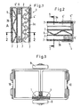
- Fig. 1 shows one end of a wall-shaped device according to the invention in cross section in order to be able to represent the position of each component of the device.
- the individual components are generally made of medium-strength steel or aluminum.
- the shape, the arrangement and the type of materials used can ent - speaking vary the desired scope.
- Fig. 1 the position of an explosion point relative to the device is represented by reference numeral A.
- the components of the device 1 are held together by a frame 2 made of U-profiles. Outside walls 3a, 3b, which can consist of perforated sheet metal, are firmly seated in this frame 2.
- the term "fixed” is used to describe the seating of the outer surfaces 3a, 3b in the supporting frame 2, which does not mean, however, that these outer surfaces 3 are welded or otherwise attached to the frame 2.
- the inner components of the device 1 are designed and arranged such that external forces act on the inner regions of the outer walls 3 in order to hold them in the support frame 2. Welding or screwing is neither necessary nor desirable.
- At least two barriers 4, 5 are arranged within the frame 2, at least one of which is a blind 4, like the blind-like parts 4 in FIG. 1.
- These blinds 4 are arranged in rows in such a way that a projectile or a splinter is not penetrated by them Protective wall can pass without touching at least a certain part of one of the blind elements 4 '.
- the Venetian blind elements 4 'V-shaped cross section and are offset from each other in such a way that the aforementioned goal is achieved. As can be seen from FIG.
- the barrier 4 consists of a first row of blind elements 4 'extending essentially in the same plane and a second row of blind elements extending essentially in a second plane running at a distance from the first plane 4 '.
- the first row of blind elements 4' is arranged at a selected distance from the second row.
- the blind elements 4 ' are fixed in relation to a movable auxiliary frame 4' ', which is described in particular with reference to FIG. 2.
- the second barrier 5 of this preferred exemplary embodiment has two relatively rigid, medium-strength metal sheets 5 'and 6.
- These sheets 5 1 and 6 are designed as corrugated sheets, the corrugations of the sheets 5' being perpendicular to the corrugations of the sheets 6. Mainly these corrugations make the protection device an excellent shock absorber.
- the corrugated sheets 5 'and 6 also deliver the outward forces which firmly support the outer walls 3a in the supporting frame 2.
- Relatively rigid corrugated sheets 5 'and 6 provide a large bending surface over which the force of an explosion can spread, so that the explosion forces are well distributed.
- each of the outer surfaces 3a, 3b has a number of openings or openings. These openings are arranged in such a way that they do not align with one another in the sheets 3a, 3b, 5 'and 6. In this way, the pressure waves and gases generated during an explosion can flow through the outer walls 3a of the barrier. However, since the breakthroughs of the various sheets are not in alignment with one another, the moving pressure wave is forced to change its direction so that part of the explosive force is reflected.
- the device according to the invention has screens 7. These screens 7 are arranged on the inside of each outer wall 3a, 3b in a preferred exemplary embodiment according to FIG. 1 and are held there. Sieves 7 are also located on the inside of the two barriers 4, 5.
- the sieves 7 generally consist of close-meshed aluminum or steel wire mesh. These screens 7 support the distribution of the fire, which can accompany an explosion.
- the individual components of the device 1 according to the invention shown in FIG. 1 result in an effective but light barrier which can be used to contain the effects of explosions in a portable or mobile container or in a fixed building.
- the barrier walls can be used as fixed walls in such a portable or mobile container or they can be used as plates are trained, which can then be used in a modular design.
- each of the barriers 4, 5 is held in place within the device 1 but is movable relative to the frame 2, the forces accompanying an explosion are controlled more effectively than at the previously known protective layers or devices is possible.
- Fig. 2 clearly shows the mechanism by which the blind elements 4 'are movable within the device.
- the blind elements 4 1 are welded or otherwise fastened to two plates 4 ′′ arranged at a distance from one another. This creates an auxiliary frame within the device 1, which consists of two plates 4 ′′ with which one end of each blind element 4 ′ is firmly connected. It is important that the plates 4 "are fixed by sieves 7 and the force generated by the corrugated sheets 5 'and 6, which presses the subframe with the blind-like arrangement 4 against the outer surface 3.
- Fig. 3 shows a portable and mobile container, which is equipped with the device according to the invention.
- the devices 1 designed according to the invention are arranged along the circumference of the container.
- a side view of such a container is shown in Fig. 4.
- Such a container also has wheels 9 and is provided with doors 10 at the end. These front doors 10, when explosive material is stored in the container, kept closed by a system of automatic locking devices 11 such as pneumatic cylinders.
- the locking system can also be designed remotely.
- the device 1 according to the invention can be designed in modules to be used in containers as shown in FIGS. 3 and 4, or it can also be produced in larger or smaller dimensions and used in various components to get protection when needed.
Landscapes
- Engineering & Computer Science (AREA)
- General Engineering & Computer Science (AREA)
- Buildings Adapted To Withstand Abnormal External Influences (AREA)
Applications Claiming Priority (2)
| Application Number | Priority Date | Filing Date | Title |
|---|---|---|---|
| US06/877,962 US4727789A (en) | 1986-06-24 | 1986-06-24 | Vented suppressive shielding |
| US877962 | 1986-06-24 |
Publications (1)
| Publication Number | Publication Date |
|---|---|
| EP0250972A1 true EP0250972A1 (fr) | 1988-01-07 |
Family
ID=25371100
Family Applications (1)
| Application Number | Title | Priority Date | Filing Date |
|---|---|---|---|
| EP87108454A Withdrawn EP0250972A1 (fr) | 1986-06-24 | 1987-06-11 | Dispositif de protection contre les effets d'une explosion |
Country Status (2)
| Country | Link |
|---|---|
| US (1) | US4727789A (fr) |
| EP (1) | EP0250972A1 (fr) |
Cited By (5)
| Publication number | Priority date | Publication date | Assignee | Title |
|---|---|---|---|---|
| DE4114538A1 (de) * | 1991-05-04 | 1992-11-12 | Hochtief Ag Hoch Tiefbauten | Bauwerk mit aufprallschutzeinrichtung |
| GB2262798A (en) * | 1991-12-24 | 1993-06-30 | British Aerospace | An aircraft cargo container |
| DE19635946A1 (de) * | 1996-09-05 | 1998-03-12 | Krauss Maffei Ag | Minenschutz |
| DE10318492A1 (de) * | 2003-04-24 | 2004-12-09 | Fraunhofer-Gesellschaft zur Förderung der angewandten Forschung e.V. | Vorrichtung zum Schutz eines Objekts |
| RU2528360C1 (ru) * | 2013-07-08 | 2014-09-10 | Олег Савельевич Кочетов | Способ взрывозащиты производственных зданий |
Families Citing this family (52)
| Publication number | Priority date | Publication date | Assignee | Title |
|---|---|---|---|---|
| ES2045097T3 (es) * | 1987-01-14 | 1994-01-16 | Cube Overseas Trading Ltd | Un inhibidor para reducir los efectos nocivos en el area circundante a la detonacion de una bomba. |
| US6117062A (en) * | 1988-12-06 | 2000-09-12 | Alhamad; Shaikh Ghaleb Mohammad Yassin | Compositions of matter for stopping fires, explosions and oxidations of materials and build up of electrostatic charges and method and apparatus for making same |
| US5500037A (en) * | 1988-12-06 | 1996-03-19 | Alhamad; Shaikh G. M. Y. | Impact Absorber |
| US5575339A (en) * | 1988-12-06 | 1996-11-19 | Alhamad; Shaikh G. M. Y. | Compositions of matter for stopping fires, explosions and oxidations of materials and build up of electrostatic charges and method and apparatus for making same |
| US5563364A (en) * | 1988-12-06 | 1996-10-08 | Alhamad; Shaikh G. M. Y. | Anti-explosion pads and their method of use |
| US5576511A (en) * | 1988-12-06 | 1996-11-19 | Alhamad; Shaikh G. M. Y. | Anti-explosion pads with steel mesh, slitted metal foil and expanded metal net |
| US6089325A (en) * | 1988-12-06 | 2000-07-18 | Yassin Alhamad; Shaikh Ghaleb Mohammad | Compositions of matter for stopping fires, explosions and oxidations of materials and build up of electrostatic charges and method and apparatus for making same |
| US5816332A (en) * | 1988-12-06 | 1998-10-06 | Alhamad; Shaikh Ghaleb Mohammad Yassin | Compositions of matter stopping fires, explosions and oxidations of materials and build up of electrostatic charges |
| JPH03105191A (ja) * | 1989-09-20 | 1991-05-01 | Nippon Scient Kk | 真空乾燥装置 |
| DE3934983A1 (de) * | 1989-10-20 | 1991-04-25 | Saelzer Sicherheitstechnik | Tuerblatt |
| DE4117194C2 (de) * | 1991-05-25 | 1994-05-19 | Krupp Ag Hoesch Krupp | Grätingsystem |
| US5267665A (en) * | 1991-09-20 | 1993-12-07 | Sri International | Hardened luggage container |
| ATE188010T1 (de) * | 1991-10-25 | 2000-01-15 | Firexx Corp | Explosionsschutzkissen und deren verwendungsverfahren |
| US5390580A (en) * | 1993-07-29 | 1995-02-21 | The United States Of America As Represented By The Secretary Of The Army | Lightweight explosive and fire resistant container |
| US5841056A (en) * | 1996-05-31 | 1998-11-24 | Hydrodyne Incorporated | Water deflector for water-gas plumes from underwater explosions |
| US5663520A (en) * | 1996-06-04 | 1997-09-02 | O'gara-Hess & Eisenhardt Armoring Co. | Vehicle mine protection structure |
| US5780761A (en) * | 1997-03-24 | 1998-07-14 | United Defense, Lp | Multi-tiered ballistic air handling grille |
| US6240858B1 (en) * | 1997-05-27 | 2001-06-05 | Michael C. Mandall | Penetration resistant panel |
| US6298607B1 (en) * | 1998-04-16 | 2001-10-09 | The University Of Toledo | Venting-membrane system to mitigate blast effects |
| US6244155B1 (en) * | 1999-03-16 | 2001-06-12 | The United States Of America As Represented By The United States Department Of Energy | Explosive parcel containment and blast mitigation container |
| US7165484B2 (en) * | 2002-09-05 | 2007-01-23 | Industrial Technology Research Institute | Blast-resistant cargo container |
| US6622607B1 (en) * | 2002-09-26 | 2003-09-23 | General Security Services Corporation | Mobile bullet resistant barrier |
| US7174692B1 (en) * | 2002-11-06 | 2007-02-13 | The United States Of America As Represented By The Secretary Of The Air Force | Blast resistant window |
| GB0307798D0 (en) * | 2003-04-04 | 2003-05-07 | Cintec Int Ltd | Impact absorbing structure |
| US20050192472A1 (en) * | 2003-05-06 | 2005-09-01 | Ch2M Hill, Inc. | System and method for treatment of hazardous materials, e.g., unexploded chemical warfare ordinance |
| US6865977B1 (en) * | 2003-07-10 | 2005-03-15 | The United States Of America As Represented By The Secretary Of The Army | Protective packaging device for blast and fragmentation mitigation |
| US6813986B1 (en) * | 2003-11-27 | 2004-11-09 | Counterterrorism Technologies Corporation | Reusable bomb diffuser |
| KR100852566B1 (ko) * | 2004-02-02 | 2008-08-18 | 비에이이 시스템즈 랜드 앤 암어먼츠 엘.피. | 수송자 보호용 장갑차 및 그 보호 방법 |
| US20070214951A1 (en) * | 2004-04-07 | 2007-09-20 | Swinson John S | Blast protection system |
| US7695053B1 (en) * | 2004-04-16 | 2010-04-13 | Bae Systems Survivability Systems, Llc | Lethal threat protection system for a vehicle and method |
| US7000550B1 (en) * | 2004-05-03 | 2006-02-21 | Mandall Michael C | Ablative blast resistant security door panel |
| GB0411724D0 (en) * | 2004-05-25 | 2004-06-30 | Aigis Engineering Solutions Lt | Blast attenuation container |
| US7878104B2 (en) | 2005-09-30 | 2011-02-01 | Armor Holdings, Inc. | Armored shell kit and associated method of armoring a vehicle |
| US7520207B1 (en) * | 2005-11-18 | 2009-04-21 | Patriot3, Inc. | Modular ballistic wall assembly |
| US7431686B2 (en) * | 2006-11-28 | 2008-10-07 | Parsons Corporation | Portable vapor containment structure |
| US7997182B1 (en) * | 2007-08-16 | 2011-08-16 | Timothy J. Cox | Protective hull for vehicles |
| JP2010243413A (ja) * | 2009-04-08 | 2010-10-28 | Canon Inc | 測定装置、露光装置及びデバイスの製造方法 |
| JP5474502B2 (ja) * | 2009-11-18 | 2014-04-16 | 沖電気工業株式会社 | 筐体 |
| EP2369290B1 (fr) * | 2010-03-26 | 2012-05-09 | ABB Oy | Enceinte d'équipement électronique pour l'extérieur et procédé pour la réalisation d'une enceinte d'équipement électronique pour l'extérieur |
| US8424473B1 (en) | 2010-04-29 | 2013-04-23 | Michael C. Mandall | Blast energy absorbing security door panel |
| GB2483267B (en) * | 2010-09-02 | 2014-10-15 | Bae Systems Plc | Armour assembly |
| US8336260B1 (en) | 2011-01-14 | 2012-12-25 | Armorworks Enterprises LLC | High security blast door lock and seal |
| US8424443B2 (en) | 2011-01-31 | 2013-04-23 | The United States Of America As Represented By The Secretary Of The Army | Vented armor V structure |
| JP2012180992A (ja) * | 2011-03-02 | 2012-09-20 | Shimizu Corp | 爆風圧低減板 |
| US20120240757A1 (en) * | 2011-03-25 | 2012-09-27 | David Arthur Schade | Composite grille louvers |
| JP5875800B2 (ja) * | 2011-08-23 | 2016-03-02 | 日油株式会社 | 弾薬用容器 |
| DE102013008941A1 (de) * | 2013-05-25 | 2014-11-27 | Diehl Bgt Defence Gmbh & Co. Kg | Anordnung zum Schutz eines Objekts, insbesondere eines Kraftfahrzeugs, gegen anfliegende Projektile |
| CN106288999B (zh) * | 2016-10-19 | 2018-03-06 | 中国人民解放军总参谋部工程兵科研三所 | 一种小口径穴型聚能装药防爆储运箱 |
| US11421962B2 (en) | 2018-02-05 | 2022-08-23 | Robert D. Bailey | Pro-active defense structure with tensioning member |
| MX2020008261A (es) * | 2018-02-05 | 2020-09-21 | Proactive Ballistic Systems Llc | Estructura de defensa proactiva. |
| US10378870B1 (en) * | 2018-05-30 | 2019-08-13 | The United States Of America As Represented By The Secretary Of The Army | Energy absorbing flange for meltable fuze plug |
| CN116648046B (zh) * | 2023-05-31 | 2026-01-20 | 南京微毫科技有限公司 | 一种安拆便捷的毫米波屏蔽箱 |
Citations (5)
| Publication number | Priority date | Publication date | Assignee | Title |
|---|---|---|---|---|
| DE565297C (de) * | 1930-10-22 | 1932-11-28 | Hofmann Walter | Biegsamer, umlegbarer, kugelsicherer Panzer mit abgefederten Abwehrplatten |
| GB535638A (en) * | 1940-05-24 | 1941-04-16 | Hunt & Turner Ltd | Improvements in protective armouring |
| DE2325921A1 (de) * | 1973-05-22 | 1974-12-12 | Karl Weber | Schussichere wandung, insbesondere fuer fahrzeuge, einschliesslich flugzeuge |
| US4347796A (en) * | 1976-06-24 | 1982-09-07 | The United States Of America As Represented By The Secretary Of The Army | Blast suppressive shielding |
| FR2547908A1 (fr) * | 1981-02-25 | 1984-12-28 | Messerschmitt Boelkow Blohm | Structure de paroi pour dispositifs de protection contre les engins perforants, tels que projectiles pleins et dards de charges creuses |
Family Cites Families (23)
| Publication number | Priority date | Publication date | Assignee | Title |
|---|---|---|---|---|
| DE333846C (de) * | 1921-03-07 | H F Peltz Fa | Geldschrank, Wertbehaelter o. dgl. mit zwischen Aussen- und Innenmantel der Wandung angeordnetem Panzermantel | |
| US679326A (en) * | 1900-10-13 | 1901-07-30 | Johan Nederland | Armor-plate. |
| US1014510A (en) * | 1911-05-13 | 1912-01-09 | Joseph N Papendry | Armor-plate. |
| US1237883A (en) * | 1916-12-07 | 1917-08-21 | Giovanni Emanuele Elia | Ship protection against submarine explosions. |
| US1736621A (en) * | 1926-06-28 | 1929-11-19 | Platt Joseph | Port shield |
| US1761095A (en) * | 1926-07-15 | 1930-06-03 | Spottswood Edwin Egmont | Protective structure for cashiers and the like |
| US2405590A (en) * | 1940-03-08 | 1946-08-13 | Bell Telephone Labor Inc | Detonation shield |
| US2315799A (en) * | 1941-06-12 | 1943-04-06 | Guardia Fiorello H La | Safety device for handling explosives |
| US2351297A (en) * | 1941-09-27 | 1944-06-13 | Martin C Schwab | Device for protection of municipalities against incendiary bombs and delayed-action bombs |
| US2393350A (en) * | 1943-05-21 | 1946-01-22 | George P Wiedman | Bullet protection guard |
| US2491516A (en) * | 1944-01-12 | 1949-12-20 | Charles S Piggot | Method and means to safely deactivate explosive bearing ordnance |
| US3109369A (en) * | 1944-05-31 | 1963-11-05 | Harold J Plumley | Disposal of encased explosives |
| NL287590A (fr) * | 1962-01-09 | |||
| US3301041A (en) * | 1964-08-28 | 1967-01-31 | Donald W Mueller | Prestressed concrete containment vessel |
| US3800715A (en) * | 1971-09-30 | 1974-04-02 | W Boller | Bomb recovery and shield apparatus |
| US3721201A (en) * | 1971-09-30 | 1973-03-20 | W Boller | Bomb recovery and shield apparatus |
| US3820435A (en) * | 1972-05-11 | 1974-06-28 | Atomic Energy Commission | Confinement system for high explosive events |
| US3820479A (en) * | 1973-02-23 | 1974-06-28 | Fmc Corp | Mobile container for safely handling explosives |
| US4325309A (en) * | 1974-08-06 | 1982-04-20 | The United States Of America As Represented By The Secretary Of The Army | Blast suppressive shielding |
| US4046055A (en) * | 1975-07-18 | 1977-09-06 | The United States Of America As Represented By The Secretary Of The Army | Apparatus for safely neutralizing explosive devices |
| US4027601A (en) * | 1976-04-19 | 1977-06-07 | The United States Of America As Represented By The Secretary Of The Army | Container for explosive device |
| US4326468A (en) * | 1976-06-24 | 1982-04-27 | The United States Of America As Represented By The Secretary Of The Army | Blast suppressive shielding |
| US4248342A (en) * | 1979-09-24 | 1981-02-03 | King Paul V | Blast suppressive shielding |
-
1986
- 1986-06-24 US US06/877,962 patent/US4727789A/en not_active Expired - Fee Related
-
1987
- 1987-06-11 EP EP87108454A patent/EP0250972A1/fr not_active Withdrawn
Patent Citations (5)
| Publication number | Priority date | Publication date | Assignee | Title |
|---|---|---|---|---|
| DE565297C (de) * | 1930-10-22 | 1932-11-28 | Hofmann Walter | Biegsamer, umlegbarer, kugelsicherer Panzer mit abgefederten Abwehrplatten |
| GB535638A (en) * | 1940-05-24 | 1941-04-16 | Hunt & Turner Ltd | Improvements in protective armouring |
| DE2325921A1 (de) * | 1973-05-22 | 1974-12-12 | Karl Weber | Schussichere wandung, insbesondere fuer fahrzeuge, einschliesslich flugzeuge |
| US4347796A (en) * | 1976-06-24 | 1982-09-07 | The United States Of America As Represented By The Secretary Of The Army | Blast suppressive shielding |
| FR2547908A1 (fr) * | 1981-02-25 | 1984-12-28 | Messerschmitt Boelkow Blohm | Structure de paroi pour dispositifs de protection contre les engins perforants, tels que projectiles pleins et dards de charges creuses |
Cited By (7)
| Publication number | Priority date | Publication date | Assignee | Title |
|---|---|---|---|---|
| DE4114538A1 (de) * | 1991-05-04 | 1992-11-12 | Hochtief Ag Hoch Tiefbauten | Bauwerk mit aufprallschutzeinrichtung |
| GB2262798A (en) * | 1991-12-24 | 1993-06-30 | British Aerospace | An aircraft cargo container |
| DE19635946A1 (de) * | 1996-09-05 | 1998-03-12 | Krauss Maffei Ag | Minenschutz |
| EP0828134A3 (fr) * | 1996-09-05 | 1998-11-25 | Krauss-Maffei Aktiengesellschaft | Protection contre les mines terrestres |
| DE10318492A1 (de) * | 2003-04-24 | 2004-12-09 | Fraunhofer-Gesellschaft zur Förderung der angewandten Forschung e.V. | Vorrichtung zum Schutz eines Objekts |
| DE10318492B4 (de) * | 2003-04-24 | 2005-08-11 | Fraunhofer-Gesellschaft zur Förderung der angewandten Forschung e.V. | Vorrichtung zum Schutz eines Objekts |
| RU2528360C1 (ru) * | 2013-07-08 | 2014-09-10 | Олег Савельевич Кочетов | Способ взрывозащиты производственных зданий |
Also Published As
| Publication number | Publication date |
|---|---|
| US4727789A (en) | 1988-03-01 |
Similar Documents
| Publication | Publication Date | Title |
|---|---|---|
| EP0250972A1 (fr) | Dispositif de protection contre les effets d'une explosion | |
| EP0897097B1 (fr) | Plaque composite pour la protection contre les mines terrestres | |
| DE2639691B2 (de) | Schutztür | |
| EP1499846B1 (fr) | Dispositif de protection pour vehicules blindes, en particulier contre les projectiles a charge creuse | |
| EP0551635B1 (fr) | Magasin pour munitions dans la tourrelle d'un véhice de combat | |
| DE3010917C2 (de) | Gefechtskopf mit einer Haupthohlladung und mindestens einer Vorhohlladung | |
| DE10119596A1 (de) | Reaktiver Panzerungsmodul | |
| DE19605230A1 (de) | Minenschutzvorrichtung | |
| DE19956197C2 (de) | Reaktiver Schutz | |
| EP0530529A1 (fr) | Transport container | |
| DE102017107482A1 (de) | Rammschutz | |
| DE4300746C2 (de) | Leichtpanzerung | |
| DE3633349A1 (de) | Durchschusshemmendes wandungselement fuer den schutz von industrieanlagen, produktionsmaschinen und dergleichen geraeten | |
| DE10318492B4 (de) | Vorrichtung zum Schutz eines Objekts | |
| DD158364B1 (de) | Schutzvorrichtung zur explosivbearbeitung von bauteilen | |
| DE202004007765U1 (de) | Panzerungsvorrichtung für Fahrzeuge | |
| DE3730371A1 (de) | Schottpanzerplatten-schweissverbindungsanordnung | |
| DE102020111534B4 (de) | Panzerung | |
| DE3418626A1 (de) | Schichtfolge zur abprallsicherung | |
| DE4237798A1 (de) | Panzerung | |
| DE2858251C1 (de) | Tragkonstruktion fuer ein gepanzertes Fahrzug mit Ioesbar anbringbaren und/oder auswechselbaren Panzerungselementen | |
| DE10028753A1 (de) | Schutzwandelement | |
| DE20118797U1 (de) | Vorrichtung zum Schutz von Objekten gegen terroristische Anschläge mittels Flugzeugen, Raketen und sonstigen Flugkörpern | |
| DE69622901T2 (de) | Sicherheitsbehälter für selbstangetriebene Flugkörper | |
| DE4106566A1 (de) | Schutzvorrichtung für gegen den Aufprall herkömmlicher Projektile geschützte Orte |
Legal Events
| Date | Code | Title | Description |
|---|---|---|---|
| PUAI | Public reference made under article 153(3) epc to a published international application that has entered the european phase |
Free format text: ORIGINAL CODE: 0009012 |
|
| 17P | Request for examination filed |
Effective date: 19871015 |
|
| AK | Designated contracting states |
Kind code of ref document: A1 Designated state(s): CH DE ES FR GB LI NL SE |
|
| 17Q | First examination report despatched |
Effective date: 19880825 |
|
| STAA | Information on the status of an ep patent application or granted ep patent |
Free format text: STATUS: THE APPLICATION HAS BEEN WITHDRAWN |
|
| 18W | Application withdrawn |
Withdrawal date: 19890324 |
|
| R18W | Application withdrawn (corrected) |
Effective date: 19890324 |
|
| RIN1 | Information on inventor provided before grant (corrected) |
Inventor name: KATSANIS, DAVID, DR. Inventor name: HENDERSON, W. PAUL |