EP0251016A1 - Befestigungseinrichtung mit Klemmhülse - Google Patents
Befestigungseinrichtung mit Klemmhülse Download PDFInfo
- Publication number
- EP0251016A1 EP0251016A1 EP87108602A EP87108602A EP0251016A1 EP 0251016 A1 EP0251016 A1 EP 0251016A1 EP 87108602 A EP87108602 A EP 87108602A EP 87108602 A EP87108602 A EP 87108602A EP 0251016 A1 EP0251016 A1 EP 0251016A1
- Authority
- EP
- European Patent Office
- Prior art keywords
- sleeve
- thread flanks
- angle
- cross sectional
- clamping
- Prior art date
- Legal status (The legal status is an assumption and is not a legal conclusion. Google has not performed a legal analysis and makes no representation as to the accuracy of the status listed.)
- Granted
Links
- 239000002184 metal Substances 0.000 claims description 4
- 238000006073 displacement reaction Methods 0.000 claims description 2
- 230000000063 preceeding effect Effects 0.000 claims 4
- 230000004323 axial length Effects 0.000 claims 1
- 229910000831 Steel Inorganic materials 0.000 description 2
- 238000005096 rolling process Methods 0.000 description 2
- 239000010959 steel Substances 0.000 description 2
- 239000000853 adhesive Substances 0.000 description 1
- 230000001070 adhesive effect Effects 0.000 description 1
- 230000000694 effects Effects 0.000 description 1
- 230000002349 favourable effect Effects 0.000 description 1
- 230000002427 irreversible effect Effects 0.000 description 1
- 238000004519 manufacturing process Methods 0.000 description 1
- 239000000463 material Substances 0.000 description 1
- 238000000034 method Methods 0.000 description 1
- 238000012986 modification Methods 0.000 description 1
- 230000004048 modification Effects 0.000 description 1
- 230000003313 weakening effect Effects 0.000 description 1
- 238000004804 winding Methods 0.000 description 1
Images
Classifications
-
- F—MECHANICAL ENGINEERING; LIGHTING; HEATING; WEAPONS; BLASTING
- F16—ENGINEERING ELEMENTS AND UNITS; GENERAL MEASURES FOR PRODUCING AND MAINTAINING EFFECTIVE FUNCTIONING OF MACHINES OR INSTALLATIONS; THERMAL INSULATION IN GENERAL
- F16D—COUPLINGS FOR TRANSMITTING ROTATION; CLUTCHES; BRAKES
- F16D1/00—Couplings for rigidly connecting two coaxial shafts or other movable machine elements
- F16D1/06—Couplings for rigidly connecting two coaxial shafts or other movable machine elements for attachment of a member on a shaft or on a shaft-end
- F16D1/08—Couplings for rigidly connecting two coaxial shafts or other movable machine elements for attachment of a member on a shaft or on a shaft-end with clamping hub; with hub and longitudinal key
- F16D1/09—Couplings for rigidly connecting two coaxial shafts or other movable machine elements for attachment of a member on a shaft or on a shaft-end with clamping hub; with hub and longitudinal key with radial clamping due to axial loading of at least one pair of conical surfaces
- F16D1/093—Couplings for rigidly connecting two coaxial shafts or other movable machine elements for attachment of a member on a shaft or on a shaft-end with clamping hub; with hub and longitudinal key with radial clamping due to axial loading of at least one pair of conical surfaces using one or more elastic segmented conical rings forming at least one of the conical surfaces, the rings being expanded or contracted to effect clamping
- F16D1/095—Couplings for rigidly connecting two coaxial shafts or other movable machine elements for attachment of a member on a shaft or on a shaft-end with clamping hub; with hub and longitudinal key with radial clamping due to axial loading of at least one pair of conical surfaces using one or more elastic segmented conical rings forming at least one of the conical surfaces, the rings being expanded or contracted to effect clamping with clamping effected by ring contraction only
- F16D1/096—Couplings for rigidly connecting two coaxial shafts or other movable machine elements for attachment of a member on a shaft or on a shaft-end with clamping hub; with hub and longitudinal key with radial clamping due to axial loading of at least one pair of conical surfaces using one or more elastic segmented conical rings forming at least one of the conical surfaces, the rings being expanded or contracted to effect clamping with clamping effected by ring contraction only the ring or rings being located between the shaft and the hub
-
- F—MECHANICAL ENGINEERING; LIGHTING; HEATING; WEAPONS; BLASTING
- F16—ENGINEERING ELEMENTS AND UNITS; GENERAL MEASURES FOR PRODUCING AND MAINTAINING EFFECTIVE FUNCTIONING OF MACHINES OR INSTALLATIONS; THERMAL INSULATION IN GENERAL
- F16C—SHAFTS; FLEXIBLE SHAFTS; ELEMENTS OR CRANKSHAFT MECHANISMS; ROTARY BODIES OTHER THAN GEARING ELEMENTS; BEARINGS
- F16C33/00—Parts of bearings; Special methods for making bearings or parts thereof
- F16C33/30—Parts of ball or roller bearings
- F16C33/58—Raceways; Race rings
- F16C33/583—Details of specific parts of races
- F16C33/586—Details of specific parts of races outside the space between the races, e.g. end faces or bore of inner ring
-
- F—MECHANICAL ENGINEERING; LIGHTING; HEATING; WEAPONS; BLASTING
- F16—ENGINEERING ELEMENTS AND UNITS; GENERAL MEASURES FOR PRODUCING AND MAINTAINING EFFECTIVE FUNCTIONING OF MACHINES OR INSTALLATIONS; THERMAL INSULATION IN GENERAL
- F16C—SHAFTS; FLEXIBLE SHAFTS; ELEMENTS OR CRANKSHAFT MECHANISMS; ROTARY BODIES OTHER THAN GEARING ELEMENTS; BEARINGS
- F16C35/00—Rigid support of bearing units; Housings, e.g. caps, covers
- F16C35/04—Rigid support of bearing units; Housings, e.g. caps, covers in the case of ball or roller bearings
- F16C35/06—Mounting or dismounting of ball or roller bearings; Fixing them onto shaft or in housing
- F16C35/07—Fixing them on the shaft or housing with interposition of an element
- F16C35/073—Fixing them on the shaft or housing with interposition of an element between shaft and inner race ring
-
- F—MECHANICAL ENGINEERING; LIGHTING; HEATING; WEAPONS; BLASTING
- F16—ENGINEERING ELEMENTS AND UNITS; GENERAL MEASURES FOR PRODUCING AND MAINTAINING EFFECTIVE FUNCTIONING OF MACHINES OR INSTALLATIONS; THERMAL INSULATION IN GENERAL
- F16C—SHAFTS; FLEXIBLE SHAFTS; ELEMENTS OR CRANKSHAFT MECHANISMS; ROTARY BODIES OTHER THAN GEARING ELEMENTS; BEARINGS
- F16C19/00—Bearings with rolling contact, for exclusively rotary movement
- F16C19/02—Bearings with rolling contact, for exclusively rotary movement with bearing balls essentially of the same size in one or more circular rows
- F16C19/04—Bearings with rolling contact, for exclusively rotary movement with bearing balls essentially of the same size in one or more circular rows for radial load mainly
- F16C19/06—Bearings with rolling contact, for exclusively rotary movement with bearing balls essentially of the same size in one or more circular rows for radial load mainly with a single row or balls
-
- F—MECHANICAL ENGINEERING; LIGHTING; HEATING; WEAPONS; BLASTING
- F16—ENGINEERING ELEMENTS AND UNITS; GENERAL MEASURES FOR PRODUCING AND MAINTAINING EFFECTIVE FUNCTIONING OF MACHINES OR INSTALLATIONS; THERMAL INSULATION IN GENERAL
- F16C—SHAFTS; FLEXIBLE SHAFTS; ELEMENTS OR CRANKSHAFT MECHANISMS; ROTARY BODIES OTHER THAN GEARING ELEMENTS; BEARINGS
- F16C2226/00—Joining parts; Fastening; Assembling or mounting parts
- F16C2226/10—Force connections, e.g. clamping
- F16C2226/16—Force connections, e.g. clamping by wedge action, e.g. by tapered or conical parts
-
- Y—GENERAL TAGGING OF NEW TECHNOLOGICAL DEVELOPMENTS; GENERAL TAGGING OF CROSS-SECTIONAL TECHNOLOGIES SPANNING OVER SEVERAL SECTIONS OF THE IPC; TECHNICAL SUBJECTS COVERED BY FORMER USPC CROSS-REFERENCE ART COLLECTIONS [XRACs] AND DIGESTS
- Y10—TECHNICAL SUBJECTS COVERED BY FORMER USPC
- Y10T—TECHNICAL SUBJECTS COVERED BY FORMER US CLASSIFICATION
- Y10T403/00—Joints and connections
- Y10T403/70—Interfitted members
- Y10T403/7047—Radially interposed shim or bushing
- Y10T403/7051—Wedging or camming
- Y10T403/7052—Engaged by axial movement
-
- Y—GENERAL TAGGING OF NEW TECHNOLOGICAL DEVELOPMENTS; GENERAL TAGGING OF CROSS-SECTIONAL TECHNOLOGIES SPANNING OVER SEVERAL SECTIONS OF THE IPC; TECHNICAL SUBJECTS COVERED BY FORMER USPC CROSS-REFERENCE ART COLLECTIONS [XRACs] AND DIGESTS
- Y10—TECHNICAL SUBJECTS COVERED BY FORMER USPC
- Y10T—TECHNICAL SUBJECTS COVERED BY FORMER US CLASSIFICATION
- Y10T403/00—Joints and connections
- Y10T403/70—Interfitted members
- Y10T403/7047—Radially interposed shim or bushing
- Y10T403/7051—Wedging or camming
- Y10T403/7052—Engaged by axial movement
- Y10T403/7056—Threaded actuator
-
- Y—GENERAL TAGGING OF NEW TECHNOLOGICAL DEVELOPMENTS; GENERAL TAGGING OF CROSS-SECTIONAL TECHNOLOGIES SPANNING OVER SEVERAL SECTIONS OF THE IPC; TECHNICAL SUBJECTS COVERED BY FORMER USPC CROSS-REFERENCE ART COLLECTIONS [XRACs] AND DIGESTS
- Y10—TECHNICAL SUBJECTS COVERED BY FORMER USPC
- Y10T—TECHNICAL SUBJECTS COVERED BY FORMER US CLASSIFICATION
- Y10T403/00—Joints and connections
- Y10T403/70—Interfitted members
- Y10T403/7062—Clamped members
- Y10T403/7064—Clamped members by wedge or cam
- Y10T403/7066—Clamped members by wedge or cam having actuator
Definitions
- the invention refers to a device of the type defined by the preamble of claim 1.
- the end stop which is constituted by a radially extending flange
- the end stop is subjected to big axial forces. These can be so big that the flange is pressed lose from the element to which it is connected, whereby the device is destroyed.
- the part of said element supporting the flange will not take part in the radial clamping, whereby the entire axial extension of the device is never fully utilized for clamping.
- the purpose of the present invention is to provide a device of the type mentioned above, by which clamping can be effected at a big force without risk for the device being destroyed and with use of the entire length of the device.
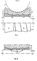
- figure 1 shows a partial longitudinal section through a device according to an embodiment of the invention
- figure 2 shows a longitudinal section through a portion of a device according to another embodiment of the invention
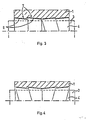
- figures 3 and 4 show partial side views of sleeves in devices according to further embodiments of the invention.
- the device shown in figure 1 has a machine element 1 in form of an inner race ring of a ball bearing, in which a ball is intimated with the line 2.
- the bearing ring is clamped upon a shaft 3, and clamping surfaces on the bearing ring and upon a clamping sleeve 4 arranged between the ring and the shaft are arranged as co-operating thread flanks 5,6, the longitudinal cross sectional contours of which form a small angle of inclination ⁇ to the axis of the sleeve. Tightening of the joint is effected in that the ring 1 is turned relative to the sleeve 4.
- At the turning two opposed mainly tapering surfaces 7,8 on the sleeve and the bearing ring resp.
- the tapering surfaces 7,8 are designed thus that the taper inclination angle ⁇ is smaller than 45°. It is thereby ascertained that a powerful and enduring radial clamping force is obtained over the sleeve also in the tapering area. The entire length of the sleeve is thus utilized for transferring clamping force.
- the small angle ⁇ gives the further advantage in comparison with an ordinary flange where the angle ⁇ is 90°, that the joint between the threaded and the tapering areas has not sharp angular change, thus that a weakening fillet effect is avoided in the area of the sleeve, where the axial pulling force is generated at tightening of the joint.
- the radial clamping on the entire length of the sleeve and the friction between the sleeve and the shaft furthermore results in that the axial pulling force will become comparatively small.
- the coefficient of friction in a contact steel against steel is about 0,15, whereby the angles are preferably smaller than about 10°.
- the friction surfaces are therefore irreversible in both contacts. This means that even if the sleeve 4 should be pulled off in the area between the taper and the thread at tightening or during operation, the radial clamping force will be maintained in both contacs, which means a big security.
- the friction in these contacts also prevents that the machine element 1 is unintentionally wound off the sleeve during operation. Such an winding off is unlikely to happen if the machine element is a bearing ring, for the reason, that the only turning moment which under operation is exerted upon the bearing ring is caused by the internal friction of the bearing, which friction is rather low.
- the angle ⁇ is preferably bigger than the angle ⁇ in order to prevent an axial sliding of the machine element 1 upon the sleeve at the tightening operation.
- the tightening means that the flat thread flanks, which define the angle ⁇ are pressed against each other, whereby an axial slot is formed between the steep, radial flanks in the threads.
- the flat thread flanks preferably have a bigger area than the area of the opposed surfaces 7,8.
- Figure 2 shows another embodiment of the invention, in which a machine element is clamped on a shaft 10 by means of a sleeve 11 made of stamped sheet metal.
- the forming method for the sleeve results in a longitudinal cross sectional profile of the internal surface of the sleeve mainly corresponding to the cross sectional profile of the outer surface.
- Such a sleeve is of low weight and is simple and cheap to manufacture. E.g. it can be formed by rolling a sheet metal belt or the like.
- the thread flanks of the bore of the sleeve are preferably bevelled at the top, whereby a cylindric helical surface 12 will contact the shaft 10.
- the surfaces 7,8 can be subdivided in a number of tapering portions the longitudinal cross sectional contours of which form a saw tooth form, such as shown in figure 3.
- the radial dimensions of the sleeve 4 therefore can be kept small.
- An axially slotted sleeve of this type can be mounted in a bore e.g. in a bearing ring by being disformed radially and thereupon being pushed into position.
- Figure 4 shows a variation of the invention where the sleeve has two threaded portions with flat thread flanks which act as clamping surfaces.
- the two threaded portions have opposed thread pitch, whereby turning of the sleeve 4 relative to the associated machine element 1 results in a clamping force occuring at the surfaces of the flat thread flanks without any axial displacement of the member 1, thereby taking place relative to sleeve 4 and shaft 3.
- the sleeve is preferably slotted in order to allow mounting in the element 1.
- the device can for instance with evident modifications be used for clamping a bearing outer racering in a housing.
- the sleeve can be non-slotted or have one or more longitudinal slots in order to reduce the deformation resistance.
- the machine element can be provided with recesses (13 in figure 1) for e.g. a hook spanner, which can be used at the turning of the element on the shaft or the sleeve.
- a sleeve normally must not be kept firm on the shaft with a specific tool, but if necessary it is of course possible to provide also the sleeve with means for co-operation with such.
- Locking of the sleeve against turning relative to the machine element can be effected e.g with a locking ring or by a portion of the sleeve being disformed plastically in a recess in the machine element. After mounting the sleeve may be entirely covered by the machine element, which is space saving in axial direction.
- a sleeve according to figure 2 can be fitted e.g to a shaft in that the cavities present between the sleeve and the shaft are filled with an adhesive.
- a sleeve which is provided with a helical surface, which contacts a smooth surface on a shaft or in a housing with a sufficient clearance, can be displaced to desired position in that it is screwed up on the shaft or into the housing. In certain cases the position can then be maintained during operation without further arrangements.
- a sleeve according to the invention can be made e.g. of metal or plastic material or combinations thereof. Mounting can be facilitated if the coefficient of friction of the sleeve against the machine element is smaller than the coefficient of friction against the shaft or against the housing.
Landscapes
- Engineering & Computer Science (AREA)
- General Engineering & Computer Science (AREA)
- Mechanical Engineering (AREA)
- Clamps And Clips (AREA)
- Mounting Of Bearings Or Others (AREA)
Applications Claiming Priority (2)
| Application Number | Priority Date | Filing Date | Title |
|---|---|---|---|
| SE8602923A SE456031B (sv) | 1986-07-01 | 1986-07-01 | Anordning for fastklemning av en lagerring med en klemhylsa |
| SE8602923 | 1986-07-01 |
Publications (2)
| Publication Number | Publication Date |
|---|---|
| EP0251016A1 true EP0251016A1 (de) | 1988-01-07 |
| EP0251016B1 EP0251016B1 (de) | 1990-08-16 |
Family
ID=20364987
Family Applications (1)
| Application Number | Title | Priority Date | Filing Date |
|---|---|---|---|
| EP87108602A Expired - Lifetime EP0251016B1 (de) | 1986-07-01 | 1987-06-15 | Befestigungseinrichtung mit Klemmhülse |
Country Status (5)
| Country | Link |
|---|---|
| US (1) | US4824277A (de) |
| EP (1) | EP0251016B1 (de) |
| JP (1) | JPS6323009A (de) |
| DE (1) | DE3764325D1 (de) |
| SE (1) | SE456031B (de) |
Cited By (2)
| Publication number | Priority date | Publication date | Assignee | Title |
|---|---|---|---|---|
| WO1994028325A1 (en) * | 1993-05-19 | 1994-12-08 | Harald Kolvereid | An arrangement for attaching ball bearings, roller bearings, gears, belt sheavers or the like onto shafts |
| DE102015114889A1 (de) | 2015-09-04 | 2017-03-09 | Festo Ag & Co. Kg | Innenspannschraube |
Families Citing this family (8)
| Publication number | Priority date | Publication date | Assignee | Title |
|---|---|---|---|---|
| JP2539357Y2 (ja) * | 1990-10-24 | 1997-06-25 | 日本電気株式会社 | 光コネクタ用光照射装置 |
| JPH04112504U (ja) * | 1991-03-20 | 1992-09-30 | 日立電子株式会社 | 空中線の合成樹脂成形金型構造 |
| SE501220C2 (sv) * | 1993-06-17 | 1994-12-12 | Etp Transmission Ab | Hydraulisk friktions-klämkoppling för axlar |
| WO1996024780A1 (de) * | 1995-02-09 | 1996-08-15 | Schäfer GmbH | Reibschlüssige drehverbindung |
| US5613795A (en) * | 1996-02-29 | 1997-03-25 | Sumitomo Machinery Corp. Of America | Conical connecting device for connecting machine components |
| US6231262B1 (en) * | 1998-09-15 | 2001-05-15 | Riverbank Company, L.P. | Hydraulically-actuated torque coupler |
| EP2407680A1 (de) * | 2010-07-14 | 2012-01-18 | Siemens Aktiengesellschaft | Welle für eine Strömungsmaschine |
| US9568037B2 (en) * | 2015-05-27 | 2017-02-14 | Tadeusz Staniszewski | Machine element mounting assembly |
Citations (6)
| Publication number | Priority date | Publication date | Assignee | Title |
|---|---|---|---|---|
| US3129038A (en) * | 1962-02-08 | 1964-04-14 | Torrington Co | Shaft mounting for roller bearing |
| FR2134966A5 (de) * | 1971-04-19 | 1972-12-08 | Textron Inc | |
| GB1430889A (en) * | 1973-05-21 | 1976-04-07 | Skf Ind Trading & Dev | Tapered clamping sleeve |
| GB2063422A (en) * | 1979-11-19 | 1981-06-03 | Skf Nova Ab | Coupling by friction |
| GB2087514A (en) * | 1980-10-09 | 1982-05-26 | Skf Ab | A coupling device |
| US4596477A (en) * | 1985-01-30 | 1986-06-24 | Skf Nova Ab | Device for fastening a machine element |
Family Cites Families (1)
| Publication number | Priority date | Publication date | Assignee | Title |
|---|---|---|---|---|
| SE443419B (sv) * | 1984-03-01 | 1986-02-24 | Skf Nova Ab | Anordning for fastsettning av ett maskinelement |
-
1986
- 1986-07-01 SE SE8602923A patent/SE456031B/sv not_active IP Right Cessation
-
1987
- 1987-06-15 EP EP87108602A patent/EP0251016B1/de not_active Expired - Lifetime
- 1987-06-15 DE DE8787108602T patent/DE3764325D1/de not_active Expired - Lifetime
- 1987-06-19 US US07/064,139 patent/US4824277A/en not_active Expired - Fee Related
- 1987-06-30 JP JP62161406A patent/JPS6323009A/ja active Granted
Patent Citations (6)
| Publication number | Priority date | Publication date | Assignee | Title |
|---|---|---|---|---|
| US3129038A (en) * | 1962-02-08 | 1964-04-14 | Torrington Co | Shaft mounting for roller bearing |
| FR2134966A5 (de) * | 1971-04-19 | 1972-12-08 | Textron Inc | |
| GB1430889A (en) * | 1973-05-21 | 1976-04-07 | Skf Ind Trading & Dev | Tapered clamping sleeve |
| GB2063422A (en) * | 1979-11-19 | 1981-06-03 | Skf Nova Ab | Coupling by friction |
| GB2087514A (en) * | 1980-10-09 | 1982-05-26 | Skf Ab | A coupling device |
| US4596477A (en) * | 1985-01-30 | 1986-06-24 | Skf Nova Ab | Device for fastening a machine element |
Cited By (2)
| Publication number | Priority date | Publication date | Assignee | Title |
|---|---|---|---|---|
| WO1994028325A1 (en) * | 1993-05-19 | 1994-12-08 | Harald Kolvereid | An arrangement for attaching ball bearings, roller bearings, gears, belt sheavers or the like onto shafts |
| DE102015114889A1 (de) | 2015-09-04 | 2017-03-09 | Festo Ag & Co. Kg | Innenspannschraube |
Also Published As
| Publication number | Publication date |
|---|---|
| DE3764325D1 (de) | 1990-09-20 |
| SE8602923D0 (sv) | 1986-07-01 |
| SE456031B (sv) | 1988-08-29 |
| US4824277A (en) | 1989-04-25 |
| JPS6323009A (ja) | 1988-01-30 |
| EP0251016B1 (de) | 1990-08-16 |
| JPH0320606B2 (de) | 1991-03-19 |
| SE8602923L (sv) | 1988-01-02 |
Similar Documents
| Publication | Publication Date | Title |
|---|---|---|
| US6095733A (en) | Threaded fastener with determinable clamp load | |
| US7857564B2 (en) | Expansion dowel | |
| CA1278990C (en) | Expander device | |
| JP2003527544A (ja) | ねじ又はねじ締付け用のナットもしくはワッシャの形態をした連結部材及びそのねじ締付け方法 | |
| EP0529134A1 (de) | Sichernde Schraube | |
| CA2565903C (en) | Taper lock bearing assembly | |
| US4555199A (en) | Support for endless grinding sleeves | |
| US4824277A (en) | Mounting device with a clamping sleeve | |
| EP0473581A1 (de) | Pflug. | |
| EP2295822A1 (de) | Schraubverbindung mit Gewindebolzen und Mutter | |
| US6428257B2 (en) | Lock nut | |
| GB2094919A (en) | Expansion anchor bolt | |
| EP0566549B1 (de) | Vorrichtung zur Montage und Demontage von Lagern | |
| CA2054389A1 (en) | Tolerance rivet for highly stressed riveted joints | |
| IE42280B1 (en) | Expanding bolt-like fastening means | |
| US3129038A (en) | Shaft mounting for roller bearing | |
| EP1262678A2 (de) | Eine Verbindungseinheit | |
| US4493597A (en) | Nut lock assembly | |
| US5795119A (en) | Adjustable lock nut | |
| GB2041135A (en) | Self-locking nut | |
| US5156507A (en) | Expansible fastening device | |
| EP0348365B1 (de) | Vorrichtung zur Sicherung eines Wälzlagerbauteiles auf einer Welle | |
| EP0450756B1 (de) | Mutternbefestigungsvorrichtung | |
| US4968175A (en) | Torque transmitting assembly | |
| EP0722049B1 (de) | Gewindebefestigung |
Legal Events
| Date | Code | Title | Description |
|---|---|---|---|
| PUAI | Public reference made under article 153(3) epc to a published international application that has entered the european phase |
Free format text: ORIGINAL CODE: 0009012 |
|
| AK | Designated contracting states |
Kind code of ref document: A1 Designated state(s): DE FR GB IT |
|
| 17P | Request for examination filed |
Effective date: 19880704 |
|
| 17Q | First examination report despatched |
Effective date: 19890519 |
|
| GRAA | (expected) grant |
Free format text: ORIGINAL CODE: 0009210 |
|
| AK | Designated contracting states |
Kind code of ref document: B1 Designated state(s): DE FR GB IT |
|
| REF | Corresponds to: |
Ref document number: 3764325 Country of ref document: DE Date of ref document: 19900920 |
|
| ET | Fr: translation filed | ||
| ITF | It: translation for a ep patent filed | ||
| PLBE | No opposition filed within time limit |
Free format text: ORIGINAL CODE: 0009261 |
|
| STAA | Information on the status of an ep patent application or granted ep patent |
Free format text: STATUS: NO OPPOSITION FILED WITHIN TIME LIMIT |
|
| ITTA | It: last paid annual fee | ||
| 26N | No opposition filed | ||
| PGFP | Annual fee paid to national office [announced via postgrant information from national office to epo] |
Ref country code: GB Payment date: 19930602 Year of fee payment: 7 |
|
| PGFP | Annual fee paid to national office [announced via postgrant information from national office to epo] |
Ref country code: FR Payment date: 19930609 Year of fee payment: 7 |
|
| PGFP | Annual fee paid to national office [announced via postgrant information from national office to epo] |
Ref country code: DE Payment date: 19930623 Year of fee payment: 7 |
|
| PG25 | Lapsed in a contracting state [announced via postgrant information from national office to epo] |
Ref country code: GB Effective date: 19940615 |
|
| GBPC | Gb: european patent ceased through non-payment of renewal fee |
Effective date: 19940615 |
|
| PG25 | Lapsed in a contracting state [announced via postgrant information from national office to epo] |
Ref country code: FR Effective date: 19950228 |
|
| PG25 | Lapsed in a contracting state [announced via postgrant information from national office to epo] |
Ref country code: DE Effective date: 19950301 |
|
| REG | Reference to a national code |
Ref country code: FR Ref legal event code: ST |
|
| PG25 | Lapsed in a contracting state [announced via postgrant information from national office to epo] |
Ref country code: IT Free format text: LAPSE BECAUSE OF NON-PAYMENT OF DUE FEES;WARNING: LAPSES OF ITALIAN PATENTS WITH EFFECTIVE DATE BEFORE 2007 MAY HAVE OCCURRED AT ANY TIME BEFORE 2007. THE CORRECT EFFECTIVE DATE MAY BE DIFFERENT FROM THE ONE RECORDED. Effective date: 20050615 |