EP0251090A2 - Vorritzsäge - Google Patents
Vorritzsäge Download PDFInfo
- Publication number
- EP0251090A2 EP0251090A2 EP87108869A EP87108869A EP0251090A2 EP 0251090 A2 EP0251090 A2 EP 0251090A2 EP 87108869 A EP87108869 A EP 87108869A EP 87108869 A EP87108869 A EP 87108869A EP 0251090 A2 EP0251090 A2 EP 0251090A2
- Authority
- EP
- European Patent Office
- Prior art keywords
- scoring
- blade
- casing
- saw
- shaft
- Prior art date
- Legal status (The legal status is an assumption and is not a legal conclusion. Google has not performed a legal analysis and makes no representation as to the accuracy of the status listed.)
- Withdrawn
Links
Images


Classifications
-
- B—PERFORMING OPERATIONS; TRANSPORTING
- B27—WORKING OR PRESERVING WOOD OR SIMILAR MATERIAL; NAILING OR STAPLING MACHINES IN GENERAL
- B27B—SAWS FOR WOOD OR SIMILAR MATERIAL; COMPONENTS OR ACCESSORIES THEREFOR
- B27B5/00—Sawing machines working with circular or cylindrical saw blades; Components or equipment therefor
- B27B5/29—Details; Component parts; Accessories
- B27B5/30—Details; Component parts; Accessories for mounting or securing saw blades or saw spindles
- B27B5/32—Devices for securing circular saw blades to the saw spindle
-
- B—PERFORMING OPERATIONS; TRANSPORTING
- B23—MACHINE TOOLS; METAL-WORKING NOT OTHERWISE PROVIDED FOR
- B23D—PLANING; SLOTTING; SHEARING; BROACHING; SAWING; FILING; SCRAPING; LIKE OPERATIONS FOR WORKING METAL BY REMOVING MATERIAL, NOT OTHERWISE PROVIDED FOR
- B23D45/00—Sawing machines or sawing devices with circular saw blades or with friction saw discs
- B23D45/06—Sawing machines or sawing devices with circular saw blades or with friction saw discs with a circular saw blade arranged underneath a stationary work-table
- B23D45/068—Sawing machines or sawing devices with circular saw blades or with friction saw discs with a circular saw blade arranged underneath a stationary work-table the saw blade being adjustable according to depth or angle of cut
-
- B—PERFORMING OPERATIONS; TRANSPORTING
- B23—MACHINE TOOLS; METAL-WORKING NOT OTHERWISE PROVIDED FOR
- B23D—PLANING; SLOTTING; SHEARING; BROACHING; SAWING; FILING; SCRAPING; LIKE OPERATIONS FOR WORKING METAL BY REMOVING MATERIAL, NOT OTHERWISE PROVIDED FOR
- B23D45/00—Sawing machines or sawing devices with circular saw blades or with friction saw discs
- B23D45/10—Sawing machines or sawing devices with circular saw blades or with friction saw discs with a plurality of circular saw blades
- B23D45/105—Sawing machines or sawing devices with circular saw blades or with friction saw discs with a plurality of circular saw blades operating within the same plane
-
- B—PERFORMING OPERATIONS; TRANSPORTING
- B23—MACHINE TOOLS; METAL-WORKING NOT OTHERWISE PROVIDED FOR
- B23D—PLANING; SLOTTING; SHEARING; BROACHING; SAWING; FILING; SCRAPING; LIKE OPERATIONS FOR WORKING METAL BY REMOVING MATERIAL, NOT OTHERWISE PROVIDED FOR
- B23D47/00—Sawing machines or sawing devices working with circular saw blades, characterised only by constructional features of particular parts
- B23D47/12—Sawing machines or sawing devices working with circular saw blades, characterised only by constructional features of particular parts of drives for circular saw blades
-
- B—PERFORMING OPERATIONS; TRANSPORTING
- B27—WORKING OR PRESERVING WOOD OR SIMILAR MATERIAL; NAILING OR STAPLING MACHINES IN GENERAL
- B27G—ACCESSORY MACHINES OR APPARATUS FOR WORKING WOOD OR SIMILAR MATERIALS; TOOLS FOR WORKING WOOD OR SIMILAR MATERIALS; SAFETY DEVICES FOR WOOD WORKING MACHINES OR TOOLS
- B27G19/00—Safety guards or devices specially adapted for wood saws; Auxiliary devices facilitating proper operation of wood saws
- B27G19/10—Measures preventing splintering of sawn portions of wood
-
- Y—GENERAL TAGGING OF NEW TECHNOLOGICAL DEVELOPMENTS; GENERAL TAGGING OF CROSS-SECTIONAL TECHNOLOGIES SPANNING OVER SEVERAL SECTIONS OF THE IPC; TECHNICAL SUBJECTS COVERED BY FORMER USPC CROSS-REFERENCE ART COLLECTIONS [XRACs] AND DIGESTS
- Y10—TECHNICAL SUBJECTS COVERED BY FORMER USPC
- Y10T—TECHNICAL SUBJECTS COVERED BY FORMER US CLASSIFICATION
- Y10T83/00—Cutting
- Y10T83/02—Other than completely through work thickness
- Y10T83/0207—Other than completely through work thickness or through work presented
- Y10T83/0215—Including use of rotary scoring blade
-
- Y—GENERAL TAGGING OF NEW TECHNOLOGICAL DEVELOPMENTS; GENERAL TAGGING OF CROSS-SECTIONAL TECHNOLOGIES SPANNING OVER SEVERAL SECTIONS OF THE IPC; TECHNICAL SUBJECTS COVERED BY FORMER USPC CROSS-REFERENCE ART COLLECTIONS [XRACs] AND DIGESTS
- Y10—TECHNICAL SUBJECTS COVERED BY FORMER USPC
- Y10T—TECHNICAL SUBJECTS COVERED BY FORMER US CLASSIFICATION
- Y10T83/00—Cutting
- Y10T83/768—Rotatable disc tool pair or tool and carrier
- Y10T83/7684—With means to support work relative to tool[s]
- Y10T83/773—Work-support includes passageway for tool [e.g., slotted table]
-
- Y—GENERAL TAGGING OF NEW TECHNOLOGICAL DEVELOPMENTS; GENERAL TAGGING OF CROSS-SECTIONAL TECHNOLOGIES SPANNING OVER SEVERAL SECTIONS OF THE IPC; TECHNICAL SUBJECTS COVERED BY FORMER USPC CROSS-REFERENCE ART COLLECTIONS [XRACs] AND DIGESTS
- Y10—TECHNICAL SUBJECTS COVERED BY FORMER USPC
- Y10T—TECHNICAL SUBJECTS COVERED BY FORMER US CLASSIFICATION
- Y10T83/00—Cutting
- Y10T83/768—Rotatable disc tool pair or tool and carrier
- Y10T83/7872—Tool element mounted for adjustment
Definitions
- the present invention relates to mechanical saws in general, more specifically to a scoring saw assembly for use with a bench saw and adapted to make a score in an article immediately prior to the cutting of the article.
- a scoring saw as a kit, which can be installed on an existing bench saw not equipped with a scoring saw and with minimum modification to the existing bench saw
- an elongated casing adapted to be rotatively mounted at one end on the main shaft of the circular saw blade of a conventional bench saw, a scoring saw rotatably carried by the free end of the casing.
- a support is adapted to be fixed to the bench and supports the free end of the casing against rotation.
- this support is movable to adjust the depth of cut of the scoring saw.
- the scoring saw blade is adjustably mounted on its shaft to bring it into precise alignment with the main saw blade.
- Driving means between the two blade shafts cooperatively function to deliver power from the main saw blade shaft to the scoring blade shaft, the latter being made to rotate in the opposite direction relative to the main blade shaft.
- the driving means is carried by the elongated casing and the main shaft.
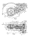
- the scoring saw assembly indicated generally at 1 is adapted for use with a conventional bench saw, the bench of which having a work supported table 2 with an elongated opening 3, as best seen in Figure 1.
- the bench saw carries its electric motor (not shown) which drives a main saw shaft 4 disposed below and parallel to table 2 and transverse to opening 3.
- shaft 4 has an integral collar 5 serving as an abutment and part of the clamping means for the larger diameter conventional circular saw blade 6 mounted on the protruding free end portion 4 ⁇ of shaft 4.
- Portion 4 ⁇ is conventionally threaded and normally an internally threaded collar (not shown) is screwed on shaft portion 4 ⁇ to clamp saw blade 6 to shaft 4.
- Blade 6 protrudes through opening 3 and more specifically through a narrow slit of a cover plate (not shown) fitting opening 3 and removably secured flush with work supporting table 2 by means of bolts screwed into threaded holes 7 of four recessed ears 8 integral with table 2 and protruding within opening 3 (see Figure 7).
- Scoring saw assembly 1 comprises an elongated one piece, cast casing 9 having a rear large annular portion 10 extended forwardly into a vertical inner wall portion 11. Wall portion 11 is formed with a first internally threaded sleeve 12 and a second longer sleeve 12a. Spaced forwardly of sleeve 12a is a small annular terminal portion 13.
- the casing is preferably made of cast aluminum.
- Large annular portion has mounted therein a double ball bearing 14 through the inner race 14 ⁇ of which slidably fits a bushing 15 which in turn slidably fits over threaded shaft portion 4 ⁇ .
- a saw blade clamping collar 16 slidably fits shaft portion 4 ⁇ between saw blade 6 and inner race 14 ⁇ and bushing 15.
- a hexagonal-head nut 17 is tightly screwed onto the end portion 4 ⁇ of the shaft 4.
- Nut 17 defines an annular shoulder at 17 ⁇ .
- Shoulder 17 ⁇ and the opposed face of inner race 14 ⁇ of ball bearing 14 combine to define a tightenable space in which is fixedly secured the hub of a large spur gear 18. It is apparent that tightening of nut 17 tightens spur gear 18, inner race 14 ⁇ , collar 16 and saw blade 6 against abutment collar 5 so that all these parts will rotate as a unit with shaft 4.
- the teeth 18 ⁇ of gear 18 are located at the end of an orthogonally bent circumferential portion 18 ⁇ (see Fig. 6) and spacedly overlap annular portion 10.
- annular portion 10 The greater portion of the circumference of annular portion 10 is integrally formed with a radially outer, guard flange 19, of L-shaped cross-section, which spacedly overlaps gear teeth 18 ⁇ to effectively protect said teeth from flying material.
- Flange 19 further extends to terminal annular portion 13 and merges with the latter, as best seen in Figure 1.
- An elongated hex-head bolt 20 has an end portion 20 ⁇ threadedly engaged in sleeve 12.
- Bolt 20 constitutes a shaft.
- gear 24 is adapted to mesh with gear 18.
- bolt 20 is fixed and the rotating elements include the outer race of bearing 21, pulley 23, neck portion 23 ⁇ and spur gear 24.
- Terminal annular portion 13 of the casing 9 is also fitted with a ball bearing 25 (see Figure 6 again) in which is journalled a small saw blade shaft 26.
- Shaft 26 carries a small, scoring saw blade 27.
- the opposite end of shaft 26 carries a driven pulley 28, the latter being screwed on threaded portion 26 ⁇ of shaft 26 and tightened at its central annular rib 28 ⁇ against the inner race of bearing 25; this inner race being in turn tightened against a shoulder 26 ⁇ of shaft 26.
- Pulley 23 drives pulley 28 by means of an endless belt 29 which preferably has a toothed inner surface 29 ⁇ to match the teeth of pulleys 23 and 28.
- FIGS 2-5 clearly show how the scoring saw of the invention functions: a long board A, coated with melamine B or other similar hard, brittle substances is fed on table 2 from right to left. Scoring blade 27 rotating in counter-clockwise direction, cuts into and not out of the bottom surface of board A, thereby preventing any chipping of the board or coating B. Then, as board A is further moved along, the main blade 6 finishes the cut, working into the top of board A, as shown. Thus a precise perfect cut is obtained without chipping at both board surfaces.
- the above described elements constitute the driving means.
- Figure 9 shows how the casing 9 may be pivoted about the axis of main shaft 11 merely by loosening bolt 33 and moving member 34 upwardly or downwardly, then retightening bolt 33 against a washer 33 ⁇ .
- scoring blade 27 can be positioned for a cut of any depth or simply lowered out of the way to permit main saw blade 6 to cut independently.
- an abutment collar 41 is first screwed around segment 38 until its flat face contacts blade 25 with the latter in alignment with main blade 6. Then another abutment collar 42 is screwed onto segment 39 until its respective flat face abuts saw blade 25 to lock the latter into place by the reverse threading of the two segments 38, 39.
- the slit of the conventional cover plate closing table opening 3 is simply extended forwardly for the passage of scoring blade 27.
Landscapes
- Engineering & Computer Science (AREA)
- Mechanical Engineering (AREA)
- Life Sciences & Earth Sciences (AREA)
- Wood Science & Technology (AREA)
- Forests & Forestry (AREA)
- Sawing (AREA)
- Processing Of Stones Or Stones Resemblance Materials (AREA)
Applications Claiming Priority (2)
| Application Number | Priority Date | Filing Date | Title |
|---|---|---|---|
| CA000512213A CA1223793A (en) | 1986-06-23 | 1986-06-23 | Scoring saw |
| CA512213 | 1986-06-23 |
Publications (2)
| Publication Number | Publication Date |
|---|---|
| EP0251090A2 true EP0251090A2 (de) | 1988-01-07 |
| EP0251090A3 EP0251090A3 (de) | 1990-01-17 |
Family
ID=4133408
Family Applications (1)
| Application Number | Title | Priority Date | Filing Date |
|---|---|---|---|
| EP87108869A Withdrawn EP0251090A3 (de) | 1986-06-23 | 1987-06-22 | Vorritzsäge |
Country Status (4)
| Country | Link |
|---|---|
| US (1) | US4706535A (de) |
| EP (1) | EP0251090A3 (de) |
| AU (1) | AU583990B2 (de) |
| CA (1) | CA1223793A (de) |
Cited By (6)
| Publication number | Priority date | Publication date | Assignee | Title |
|---|---|---|---|---|
| NL8801939A (nl) * | 1988-08-03 | 1990-03-01 | Sallmetall Bv | Werkwijze en inrichting voor het snijden van sandwichpanelen. |
| EP0455592A1 (de) * | 1990-05-02 | 1991-11-06 | Striebig AG | Sägeaggregat für vertikale Plattensäge |
| EP0447371A3 (en) * | 1990-03-12 | 1991-11-13 | Euromac S.P.A. | Device for adjusting the axial position of a rotary tool |
| AT400826B (de) * | 1994-07-14 | 1996-03-25 | Schelling & Co | Verfahren zum einstellen eines vorritzers gegenüber einem trennsägeblatt und vorrichtung zur durchführung des verfahrens |
| GB2293347A (en) * | 1994-09-20 | 1996-03-27 | Neil Andrew Murray | Sawing apparatus |
| WO2021116480A1 (de) * | 2019-12-13 | 2021-06-17 | Festool Gmbh | Vorritzwerkzeug für eine sägemaschine |
Families Citing this family (23)
| Publication number | Priority date | Publication date | Assignee | Title |
|---|---|---|---|---|
| IT1213905B (it) * | 1987-09-24 | 1990-01-05 | Giben Impianti Spa | Metodo ed apparato per la sezionatura fine di pannelli o pacchi dipannelli con l impiego di una sola sega a disco |
| CA2036447C (en) * | 1991-02-15 | 1994-08-16 | Michel Letendre | Assembly for conventional bench saw |
| US5159870A (en) * | 1991-08-15 | 1992-11-03 | Fiala Paul E | Portable electric cutting and scoring saw |
| US5193428A (en) * | 1991-12-03 | 1993-03-16 | Michel Letendre | Assembly for conventional bench saw |
| AUPM327294A0 (en) * | 1994-01-10 | 1994-02-03 | Bishop, John Waldron | Twin blade saw |
| EP0930121B1 (de) * | 1994-12-02 | 2002-04-24 | Makita Corporation | Schneidwerkzeugaufspannvorrichtung |
| IT1279652B1 (it) * | 1995-10-11 | 1997-12-16 | Selco Srl | Macchina per il taglio di pezzi. |
| US5901631A (en) * | 1997-09-18 | 1999-05-11 | Minarovic; Mike | Wood notching system |
| US5979525A (en) * | 1998-08-18 | 1999-11-09 | Durney; Max W. | Method and apparatus for scoring a workpiece in advance of sawing |
| JP2001347416A (ja) * | 2000-06-06 | 2001-12-18 | Matsushita Electric Ind Co Ltd | 切断装置及び切断方法 |
| DE10302066A1 (de) * | 2003-01-21 | 2004-07-29 | Kolbus Gmbh & Co. Kg | Vorrichtung zum Trennsägen von Doppelnutzen |
| DE10312865A1 (de) * | 2003-03-18 | 2004-10-07 | Reich Spezialmaschinen Gmbh | Sägeaggregat |
| US7240598B2 (en) * | 2004-10-20 | 2007-07-10 | Chun-Hsiang Wang | Power transmission structure with dual blade shaft of a circular saw |
| DE102006011131B3 (de) * | 2006-03-10 | 2007-09-13 | Holzma Plattenaufteiltechnik Gmbh | Sägevorrichtung |
| PL3164250T3 (pl) * | 2014-07-02 | 2019-03-29 | Panotec Srl | Tnące urządzenie do cięcia względnie sztywnego materiału |
| US10493543B2 (en) * | 2015-03-12 | 2019-12-03 | Robert Bosch Tool Corporation | Power tool motor with reduced electrical noise |
| SE540907C2 (en) * | 2016-11-03 | 2018-12-18 | Husqvarna Ab | A dust removal arrangement for an engine-driven tool |
| JP7152164B2 (ja) * | 2018-02-21 | 2022-10-12 | ケイミュー株式会社 | 切断方法及び切断装置 |
| US12294204B2 (en) | 2019-05-23 | 2025-05-06 | Southwire Company, Llc | Armored cable stripping tool for cutting the armor in two places |
| DE102019134411A1 (de) * | 2019-12-13 | 2021-06-17 | Festool Gmbh | Mobile Hand-Sägemaschine mit einem schwenkbaren Vorritzaggregat |
| DE102019134416A1 (de) * | 2019-12-13 | 2021-06-17 | Festool Gmbh | Mobile Hand-Sägemaschine mit Vorritzwerkzeug an Längsseite |
| DE102019134412B4 (de) * | 2019-12-13 | 2023-12-14 | Festool Gmbh | Mobile Hand-Sägemaschine mit Vorritzaggregat und Werkzeugwechsel |
| CN118616814B (zh) * | 2024-05-28 | 2025-01-24 | 广州市义统包装制品有限公司 | 一种茶叶包装罐生产用的切割装置 |
Family Cites Families (13)
| Publication number | Priority date | Publication date | Assignee | Title |
|---|---|---|---|---|
| FR1181179A (fr) * | 1957-08-14 | 1959-06-12 | Dispositif de montage de lames sectionneuses rotatives | |
| AT283704B (de) * | 1966-07-09 | 1970-08-25 | Gino Benuzzi | Tischkreissäge |
| DE2540109C3 (de) * | 1975-09-09 | 1978-05-24 | F. Meyer & Schwabedissen Gmbh & Co Kg, 4900 Herford | Kreissäge mit zwei gegenläufig angetriebenen Sägeblättern |
| US4058150A (en) * | 1976-03-09 | 1977-11-15 | Pennington Charles A | Wood cutting apparatus |
| DE2740673A1 (de) * | 1976-09-20 | 1978-03-23 | Giben Impianti Spa | Kreissaegemaschine fuer platten, plattenpakete o.dgl. |
| IT1081442B (it) * | 1977-06-07 | 1985-05-21 | Putsch Meniconi Srl | Testa operatrice per macchina sezionatrice di pannelli specialmente in legno a superficie vista in laminato plastico |
| SU666076A1 (ru) * | 1977-08-10 | 1979-06-09 | Краснодарское Специализированное Проектно-Конструкторское Бюро "Союзорглестехмонтаж" | Станок дл раскро отделанных плит |
| US4176572A (en) * | 1978-01-23 | 1979-12-04 | Pennington Charles A | Device for scoring wood panels prior to sawing |
| US4245390A (en) * | 1979-03-30 | 1981-01-20 | Bond David L | Scoring attachment for power saws |
| BR7903150A (pt) * | 1979-05-21 | 1980-11-25 | Rockwell Brasil Ind Com | Serra de mesa |
| IT1145521B (it) * | 1981-10-20 | 1986-11-05 | Giben Impianti Spa | Dispositivo incisore, particolarmente adatto per le macchine e per gli impianti adibiti alla sezionatura di pannelli di legno e/od in altro materiale |
| DE3439443A1 (de) * | 1984-10-27 | 1986-04-30 | Wilhelm Altendorf GmbH & Co KG, 4950 Minden | Verfahren zum trennenden saegen von werkstuecken |
| DE3501657A1 (de) * | 1985-01-19 | 1986-07-24 | Reich Spezialmaschinen GmbH, 7440 Nürtingen | Vorrichtung zum vorritzen von werkstuecken |
-
1986
- 1986-06-23 CA CA000512213A patent/CA1223793A/en not_active Expired
-
1987
- 1987-02-17 US US07/015,948 patent/US4706535A/en not_active Expired - Fee Related
- 1987-06-17 AU AU74438/87A patent/AU583990B2/en not_active Ceased
- 1987-06-22 EP EP87108869A patent/EP0251090A3/de not_active Withdrawn
Cited By (11)
| Publication number | Priority date | Publication date | Assignee | Title |
|---|---|---|---|---|
| NL8801939A (nl) * | 1988-08-03 | 1990-03-01 | Sallmetall Bv | Werkwijze en inrichting voor het snijden van sandwichpanelen. |
| US4984615A (en) * | 1988-08-03 | 1991-01-15 | 501 Sallmetall Bv | Method and device for cutting a sandwich panel |
| EP0447371A3 (en) * | 1990-03-12 | 1991-11-13 | Euromac S.P.A. | Device for adjusting the axial position of a rotary tool |
| EP0455592A1 (de) * | 1990-05-02 | 1991-11-06 | Striebig AG | Sägeaggregat für vertikale Plattensäge |
| AT400826B (de) * | 1994-07-14 | 1996-03-25 | Schelling & Co | Verfahren zum einstellen eines vorritzers gegenüber einem trennsägeblatt und vorrichtung zur durchführung des verfahrens |
| DE19520108B4 (de) * | 1994-07-14 | 2007-02-08 | Schelling Anlagenbau Gmbh | Unterflurkreissägemaschine mit Vorritzer |
| GB2293347A (en) * | 1994-09-20 | 1996-03-27 | Neil Andrew Murray | Sawing apparatus |
| WO2021116480A1 (de) * | 2019-12-13 | 2021-06-17 | Festool Gmbh | Vorritzwerkzeug für eine sägemaschine |
| CN114786856A (zh) * | 2019-12-13 | 2022-07-22 | 费斯托工具有限责任公司 | 用于锯切机器的预先划刻工具 |
| JP2023517409A (ja) * | 2019-12-13 | 2023-04-26 | フェスツール ゲーエムベーハー | 鋸機のための筋目入れ工具 |
| JP7696839B2 (ja) | 2019-12-13 | 2025-06-23 | フェスツール ゲーエムベーハー | 鋸機のための筋目入れ工具 |
Also Published As
| Publication number | Publication date |
|---|---|
| AU583990B2 (en) | 1989-05-11 |
| AU7443887A (en) | 1987-12-24 |
| US4706535A (en) | 1987-11-17 |
| CA1223793A (en) | 1987-07-07 |
| EP0251090A3 (de) | 1990-01-17 |
Similar Documents
| Publication | Publication Date | Title |
|---|---|---|
| US4706535A (en) | Scoring saw | |
| US5148732A (en) | Saw unit for a vertical board saw | |
| US5433008A (en) | Circular saw with variable adjustment stops | |
| US4694721A (en) | Motor pack for circular saw | |
| CA2211988C (en) | Depth-of-cut mechanism for circular saw | |
| US4599927A (en) | Tool elevation and bevel adjustment for direct drive power tool | |
| US3721141A (en) | Movable blade guard and mounting for portable circular saws | |
| US5235889A (en) | Compound miter saw | |
| US4283977A (en) | Motorized miter chop saw with work-piece clamp | |
| US5287786A (en) | Portable electric cutting and scoring saw | |
| CA2129320A1 (en) | Chop/table saw with parallelogram arrangement | |
| US6971297B1 (en) | Guard and control apparatuses for sliding compound miter saw | |
| US4308777A (en) | Panel scoring table saw | |
| CA2132195A1 (en) | Mounting arbor for saw cutting blades | |
| CA2150089A1 (en) | Bevel angle adjustment mechanism for a compound miter saw | |
| US3735489A (en) | Hand-held power tool with rotary tool disc at end of reversible forwardly projecting arm | |
| US3706332A (en) | Circular saw guard and linkage | |
| EP0292246B2 (de) | Holzbearbeitungswerkzeug | |
| US5724740A (en) | Twin blade saw | |
| US3733701A (en) | Lower guard for circular saws | |
| US3382578A (en) | Portable cutting tools | |
| US2792858A (en) | Power train for tilt arbor saw | |
| US6173635B1 (en) | Base structure of a circular saw | |
| US2955629A (en) | Portable power-driven saw guard | |
| US4922780A (en) | Sawmill edger |
Legal Events
| Date | Code | Title | Description |
|---|---|---|---|
| PUAI | Public reference made under article 153(3) epc to a published international application that has entered the european phase |
Free format text: ORIGINAL CODE: 0009012 |
|
| AK | Designated contracting states |
Kind code of ref document: A2 Designated state(s): AT BE CH DE ES FR GB GR IT LI LU NL SE |
|
| PUAL | Search report despatched |
Free format text: ORIGINAL CODE: 0009013 |
|
| AK | Designated contracting states |
Kind code of ref document: A3 Designated state(s): AT BE CH DE ES FR GB GR IT LI LU NL SE |
|
| 17P | Request for examination filed |
Effective date: 19900625 |
|
| 17Q | First examination report despatched |
Effective date: 19910910 |
|
| STAA | Information on the status of an ep patent application or granted ep patent |
Free format text: STATUS: THE APPLICATION IS DEEMED TO BE WITHDRAWN |
|
| 18D | Application deemed to be withdrawn |
Effective date: 19920324 |