EP0251263A2 - Staubsauger in Kleinformat - Google Patents
Staubsauger in Kleinformat Download PDFInfo
- Publication number
- EP0251263A2 EP0251263A2 EP87109290A EP87109290A EP0251263A2 EP 0251263 A2 EP0251263 A2 EP 0251263A2 EP 87109290 A EP87109290 A EP 87109290A EP 87109290 A EP87109290 A EP 87109290A EP 0251263 A2 EP0251263 A2 EP 0251263A2
- Authority
- EP
- European Patent Office
- Prior art keywords
- suction
- housing
- brushes
- vacuum cleaner
- driven
- Prior art date
- Legal status (The legal status is an assumption and is not a legal conclusion. Google has not performed a legal analysis and makes no representation as to the accuracy of the status listed.)
- Granted
Links
Images

Classifications
-
- A—HUMAN NECESSITIES
- A47—FURNITURE; DOMESTIC ARTICLES OR APPLIANCES; COFFEE MILLS; SPICE MILLS; SUCTION CLEANERS IN GENERAL
- A47L—DOMESTIC WASHING OR CLEANING; SUCTION CLEANERS IN GENERAL
- A47L5/00—Structural features of suction cleaners
- A47L5/12—Structural features of suction cleaners with power-driven air-pumps or air-compressors, e.g. driven by motor vehicle engine vacuum
- A47L5/22—Structural features of suction cleaners with power-driven air-pumps or air-compressors, e.g. driven by motor vehicle engine vacuum with rotary fans
- A47L5/28—Suction cleaners with handles and nozzles fixed on the casings, e.g. wheeled suction cleaners with steering handle
- A47L5/30—Suction cleaners with handles and nozzles fixed on the casings, e.g. wheeled suction cleaners with steering handle with driven dust-loosening tools, e.g. rotating brushes
Definitions
- the invention relates to a vacuum cleaner in small format according to the preamble of claim 1.
- the purpose of the invention is to provide an easily portable vacuum cleaner with which objects can be cleaned by suction, such as e.g. upholstery, curtains, car interiors, carpets and the like.
- Small-sized vacuum cleaners are known here, in which several batteries are arranged one behind the other in a handle.
- This handle opens into a plastic head in which a drive motor and a turbine are arranged.
- the drive motor is powered by the batteries, and from a front suction opening, which is surrounded by a fixed brush ring, the air is sucked through the turbine into a dust bag located at the rear, where the dirt is deposited.
- the disadvantage of this arrangement is that such a manually operated dust brush or vacuum cleaner has a very poor cleaning performance.
- the drive with batteries results in very poor efficiency and suction performance.
- there is only a fixed brush ring which results in a poor cleaning effect
- the air flow through this device is so bad because of the low power of the turbine that only coarse, relatively loosely fitting dirt can be picked up.
- the present invention has set itself the task of developing a vacuum cleaner of the type mentioned in such a way that a substantially better suction power with a substantially improved cleaning effect can be achieved with approximately the same space requirement.
- the invention is characterized in that rotatably driven brushes are arranged in the area of the suction slots and pick up the dirt from the surface to be cleaned and transport it in the direction of the suction slots.
- the motor and transmission as well as the suction turbine and dust bag are arranged in a single housing, the housing being approximately elongated and rectangular in cross section, so that a compact structure results.
- the brushes are designed as rotating, roller-shaped brushes and several brushes always work in pairs so that a pair of brushes is driven in opposite directions and between them the suction opening for sucking in the dirt.
- All suction openings are connected to the dust bag via a common channel, the dust bag itself being arranged in the housing and being held there in an easily replaceable manner by an associated flap in the housing.
- the dust bag is arranged outside the housing.
- the dust bag as a replaceable cassette in the Housing is insertable.
- a suction indicator can be attached in the housing, which indicates the filling level of the dust bag.
- a suction indicator can be attached in the housing, which indicates the filling level of the dust bag.
- the counter-rotating brushes consist of a bristle material, but the brushes can also consist of wire bristles, so that it is possible with the handheld vacuum cleaner to dedust, de-rust, polish the surface and remove paint.
- a preferred embodiment of a hand-held vacuum cleaner provides a motor with a drive power of approximately 100 watts, which is driven with 220 volts, and excellent suction power is achieved in this way.
- This motor and the suction turbine driven by it preferably have a speed of 15,000 revolutions per minute, and the reduction gear assigned to the motor works in a ratio of 1: 2 on the output shaft for driving the brushes, so that the output shaft rotates at about 7500 revolutions.
- Pinions are arranged on the output shaft in a rotationally fixed manner, counter-rotating pinions being provided one behind the other, so that the roller-shaped brushes lying in one plane are driven in opposite directions.
- the pinions work on gears, which in turn are connected to the brush rollers in a rotationally fixed manner, and again a reduction ratio of 1:20 is achieved, so that in a preferred exemplary embodiment the brushes are roughly with rotate at a speed of 375 revolutions per minute.
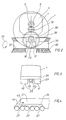
- the handheld vacuum cleaner consists of a housing 1, which has a beveled top surface 2 to the front, so that the handheld vacuum cleaner can also be easily moved under low objects.
- the housing encloses a receiving space 3 for a motor 4, which is rotatably connected with its drive shaft 5 to a first gear 6, which works on a second gear 7, which is mounted on the one hand in a bearing plate 8 on the motor and on the other hand in a flange 9 of the Reduction gear.
- This gear 7 is connected in a rotationally fixed manner to a shaft 10, which in turn is connected in a rotationally fixed manner to the turbine wheel 11, which is arranged in a further receiving space 12.
- the receiving space is delimited by a rear wall 13, in which an opening 14 is arranged, while the receiving space 12 is defined at the front by a closed wall 15.
- the wall 15 forms the rear wall of a front terminal space 16, which is used for the cable entry of the power cable and for attaching the strain relief.
- the receiving space 3 is delimited in the direction of the dust bag 21 by a rear wall 22, in which a plurality of openings 23 are arranged for the air to flow through.
- This wall 22 serves as a safety when the dust bag 21 is removed so that the user cannot reach into the motor from the chamber 24 in which the dust bag is arranged.
- the dust bag itself is interchangeably arranged in the chamber 24 in a manner not shown in detail and takes up the dirt via the suction nozzles 25.
- suction nozzles 25 lie in parallel on a channel 26 and the channel 26 is in turn connected to the chamber 24 in an air-tight manner.
- the suction nozzles 25 are profiled approximately triangular in cross-section and have a front split suction slot 27. After the brushes 32, 33 are present in pairs and have a mutual spacing in the middle, a suction slot 27 is assigned to each brush 32, 33.
- the opposing drive of the brush pairs 32, 33 is now carried out as follows:
- this gear 7 meshes with a gear 28 which is connected in a rotationally fixed manner to an output shaft 29.
- the output shaft 29 is rotatably mounted in a bearing plate 37 on the rear of the housing 1 and in a front bearing plate 38 on the front of the housing 1.
- the output shaft 29 is rotatably connected to a gear 30, the gear 30 in turn meshing with a pinion 31, which is rotatably connected to a shaft 39, which shaft 39 is rotatably connected to the brushes 32,33.
- suction slot 27 is arranged between two pairs of brushes 32, 33 driven in opposite directions.
- FIG. 3 shows the housing again in the front view and the channel 26 is shown in broken lines, which is connected in an air-tight manner to the divided suction slot 27, wherein one suction opening 40, 41 is assigned to one suction slot 27.
- FIG. 4 shows again schematically how the suction slots 27 are connected to the channel 26 in an air-tight manner and the channel in turn opens into the dust bag 21 with a front mouth 42, so that the air is deflected in the direction of arrow 43 at the mouth.
- the entire mechanism is mounted in the area of a base plate 36, which forms the underside of the housing 1, additional bearing points 44 being arranged in the area of the base plate 36 for the output shaft 29.
- this housing shell 45 The purpose of this housing shell 45 is to hold and cover the pinions 31 for driving the pairs of brushes 32, 33. If the housing shell 45 is removed, the brush pairs 32, 33 fall down with the shaft 39 and can thus be exchanged easily.
- the chamber 24 is connected to the dust bag 21 with a corresponding filling indicator.
- each pair of brushes 32, 33 carries the dirt lying on the surface to be cleaned directly to the suction slot 27, so that an excellent cleaning effect is provided.
Landscapes
- Nozzles For Electric Vacuum Cleaners (AREA)
- Filters For Electric Vacuum Cleaners (AREA)
Abstract
Description
- Die Erfindung betrifft einen Staubsauger in Kleinformat nach dem Oberbegriff des Patentanspruchs 1. Zweck der Erfindung ist, einen leicht transportablen Staubsauger zu schaffen, mit dem man Gegenstände durch Absaugen reinigen kann, wie z.B. Polster, Vorhänge, Auto-Innenräume, Teppiche und dergleichen.
- Bekannt sind hierbei Staubsauger in Kleinformat, bei denen in einem Handgriff mehrere Batterien hintereinanderliegend angeordnet sind. Dieser Handgriff mündet in einen Kopf aus Kunststoff, in dem ein Antriebsmotor und eine Turbine angeordnet ist. Der Antriebsmotor wird von den Batterien angetrieben, und von einer vorderen Ansaugöffnung her, die mit einem feststehenden Bürstenkranz umgeben ist, wird die Luft durch die Turbine in einen hinten angebrachten Staubsack hindurchgesaugt, wo der Schmutz sich niederschlägt. Nachteil dieser Anordnung ist, daß eine derartige handbetätigte Staubbürste oder Staubsauger eine sehr schlechte Reinigungsleistung hat. Zum ersten ergibt der Antrieb mit Batterien einen sehr schlechten Wirkungsgrad und eine sehr schlechte Saugleistung. Zum zweiten ist nur ein feststehender Bürstenkranz vorhanden, was eine schlechte Reinigungswirkung ergibt,und zum dritten ist der Luftdurchsatz durch dieses Gerät wegen der geringen Leistung der Turbine so schlecht, daß nur grober, relativ locker sitzender Schmutz aufgenommen werden kann.
- Die vorliegende Erfindung hat sich die Aufgabe gestellt, einen Staubsauger der eingangs genannten Art so weiterzubilden, daß bei etwa gleichem Raumbedarf eine wesentlich bessere Saugleistung mit einer wesentlich verbesserten Reinigungswirkung erbracht werden kann.
- Zur Lösung der gestellten Aufgabe ist die Erfindung dadurch gekennzeichnet, daß im Bereich der Ansaugschlitze drehend angetriebene Bürsten angeordnet sind, welche den Schmutz von der zu reinigenden Fläche aufnehmen und in Richtung auf die Ansaugschlitze transportieren.
- In einer Ausführungsform wird es hierbei bevorzugt, wenn Motor und Getriebe sowie Saugturbine und Staubsack in einem einzigen GEhäuse angeordnet sind, wobei das Gehäuse etwa länglich und im Querschnitt rechteckförmig ausgebildet ist, so daß sich ein gedrängter Aufbau ergibt.
- Hierbei wird bevorzugt, wenn die Bürsten als rotierende, walzenförmige Bürsten ausgebildet sind und mehrere Bürsten stets paarweise so zusammenarbeiten, daß jeweils ein Paar von Bürsten gegenläufig angetrieben ist und zwischen sich die Ansaugöffnung zum Ansaugen des Schmutzes aufnimmt.
- Hierdurch wird eine ausgezeichnete Reinigungswirkung erzielt, denn die gegenläufig rotierenden Bürsten arbeiten dann jeweils für sich in Richtung auf die Ansaugöffnung und können so einfach den Schmutz von der zu reinigenden Fläche aufnehmen und in Richtung zur Ansaugöffnung transportieren.
- Alle Ansaugöffnungen sind über einen gemeinsamen Kanal mit dem Staubsack verbunden, wobei der Staubsack selbst in dem Gehäuse angeordnet ist und durch eine zugeordnete Klappe im Gehäuse leicht auswechselbar dort gehalten ist.
- In einer anderen Ausführungsform könnte es auch vorgesehen sein, daß der Staubsack außerhalb des Gehäuses angeordnet ist.
- Und in einer dritten Ausführungsform könnte es vorgesehen sein, daß der Staubsack als auswechselbare Kassette in das Gehäuse einschiebbar ist.
- In dem Gehäuse kann noch zusätzlich eine Sauganzeige angebracht werden, welche den Füllungsgrad des Staubsackes anzeigt. Ferner ist noch ein Ein- und Ausschalter vorhanden und evtl. ein Überlastungsschutz, der dann auslöst, wenn der Motor überlastet wird.
- Wichtig ist hierbei, daß nach der Erfindung nicht nur vorgesehen ist, daß die gegenläufig rotierenden Bürsten aus einem Borstenmaterial bestehen, sondern die Bürsten können auch aus Drahtborsten bestehen, so daß es mit dem Handstaubsauger möglich ist, Fläche zu entstauben, zu entrosten, zu polieren und Lack zu entfernen.
- Eine bevorzugte Ausführungsform eines Handstaubsaugers sieht einen Motor mit etwa einer Antriebsleistung von 100 Watt vor, der mit 220 Volt angetrieben wird, hierdurch wird eine ausgezeichnete Saugleistung erreicht.
- Dieser Motor und die von ihm angetriebene Saugturbine haben bevorzugt eine Umdrehungszahl von 15000 Umdrehungen pro Minute, und das dem Motor zugeordnete Untersetzungsgetriebe arbeitet im Verhältnis von 1 : 2 auf die Abtriebswelle zum Antrieb der Bürsten, so daß die Abtriebswelle mit etwa 7500 Umdrehungen rotiert.
- Auf der Abtriebswelle sind drehfest Ritzel angeordnet, wobei jeweils hintereinander liegend gegenläufige Ritzel vorgesehen sind, so daß die in einer Ebene liegenden walzenförmigen Bürsten gegenläufig angetrieben werden.
- Die Ritzel arbeiten auf Zahnräder, die wiederum drehfest mit den Bürstenwalzen verbunden sind und hierbei wird wiederum ein Untersetzungsverhältnis von 1 : 20 erreicht, so daß die Bürsten in einem bevorzugten Ausführungsbeispiel etwa mit einer Drehzahl von 375 Umdrehungen pro Minute rotieren.
- Der Erfindungsgegenstand der vorliegenden Erfindung ergibt sich nicht nur aus dem Gegenstand der einzelnen Patentansprüche, sondern auch aus der Kombination der einzelnen Patentansprüche untereinander. Alle in den Unterlagen offenbarten Angaben und Merkmale, insbesondere die in den Zeichnungen dargestellte räumliche Ausbildung werden als erfindungswesentlich beansprucht, soweit sie einzeln oder in Kombination gegenüber dem Stand der Technik neu sind.
- Im folgenden wird die Erfindung anhand von lediglich einen Ausführungsweg darstellende Zeichnungen näher erläutert. Hierbei gehen aus den Zeichnungen und ihrer Beschreibung weitere erfindungswesentliche Merkmale und Vorteile der Erfindung hervor.
- Es zeigen:
- Figur 1: Längsschnitt durch einen Staubsauger nach der Erfindung,
- Figur 2: schematisiert gezeichnete Stirnansicht des Staubsaugers,
- Figur 3: eine weitere Stirn_ansicht des Staubsaugers mit Darstellung der Luftführung,
- Figur 4: schematisiert den Staubsauger in der Seitenansicht mit Darstellung der Luftführung.
- Der Handstaubsauger besteht aus einem Gehäuse 1, welches nach vorne eine abgeschrägte Deckfläche 2 aufweist, damit mit dem Handstaubsauger auch leicht unter niedrige Gegenstände gefahren werden kann.
- Das Gehäuse umschließt einen Aufnahmeraum 3 für einen Motor 4, der mit seiner Antriebswelle 5 drehfest mit einem ersten Zahnrad 6 verbunden ist, welches auf ein zweites Zahnrad 7 arbeitet, welches einerseits in einem Lagerschild 8 am Motor gelagert ist und andererseits in einem Flansch 9 des Untersetzungsgetriebes. Dieses Zahnrad 7 ist drehfest mit einer Welle 10 verbunden, die ihrerseits drehfest mit dem Turbinenrad 11 verbunden ist, welches in einem weiteren Aufnahmeraum 12 angeordnet ist. Der Aufnahmeraum wird durch eine hintere Wand 13 begrenzt, in der eine Öffnung 14 angeordnet ist, während nach vorne der Aufnahmeraum 12 durch eine geschlossene Wand 15 definiert ist. Die Wand 15 bildet die Rückwand eines vorderen Anklemmraumes 16, der zur Kabeleinführung des Netzkabels und zur Anbringung der Zugentlastung dient.
- Der von dem Turbinenrad 11 in Pfeilrichtung 17 angesaugte Luftstrom wird in Pfeilrichtung 18 radial aus dem Gehäuse durch entsprechende Ausblasschlitze herausgeblasen.
- Wichtig ist noch, daß der von der Turbine angesaugte Luftstrom in Pfeilrichtung 19 den Motor durchströmt. Ebenso strömt die Luft in Pfeilrichtung 19 auch durch einen oberen und unteren den Motor 4 umgebenden Kanal 20 im Aufnahmeraum 3.
- Der Aufnahmeraum 3 wird in Richtung zum Staubsack 21 durch eine hintere Wand 22 begrenzt, in der eine Vielzahl von Öffnungen 23 für die Durchströmung der Luft angeordnet ist.
- Diese Wand 22 dient als Sicherheit, wenn der Staubsack 21 entfernt wird, daß von Seiten der Kammer 24, in welcher der Staubsack angeordnet ist, der Benutzer nicht in den Motor hineingreifen kann.
- Der Staubsack selbst ist in nicht näher dargestellter Weise auswechselbar in der Kammer 24 angeordnet und nimmt über die Saugdüsen 25 den Schmutz auf.
- Wichtig hierbei ist, daß mehrere Saugdüsen 25 parallel an einem Kanal 26 liegen und der Kanal 26 seinerseits luftschlüssig mit der Kammer 24 verbunden ist.
- Die Saugdüsen 25 sind hierbei im Querschnitt etwa dreiecksförmig profiliert und weisen einen vorderen geteilten Ansaugschlitz 27 auf. Nachdem die Bürsten 32,33 paarweise vorhanden sind und in der Mitte einen gegenseitigen Abstand aufweisen, ist jeder Bürste 32,33 ein Ansaugschlitz 27 zugeordnet. Der gegenläufige Antrieb der Bürstenpaare 32,33 erfolgt nun wie folgt:
- Von dem Zahnrad 7 für den Antrieb des Turbinenrades 11 ausgehend kämmt mit diesem Zahnrad 7 ein Zahnrad 28, welches drehfest mit einer Abtriebswelle 29 verbunden ist. Die Abtriebswelle 29 ist in einem Lagerschild 37 an der Hinterseite des Gehäuses 1 und in einem vorderen Lagerschild 38 an der Vorderseite des Gehäuses 1 drehbar gelagert.
- Gemäß Figur 2 ist die Abtriebswelle 29 jeweils drehfest mit einem Zahnrad 30 verbunden, wobei das Zahnrad 30 jeweils wiederum mit einem Ritzel 31 kämmt, welches drehfest mit einer Welle 39 verbunden ist, welche Welle 39 drehfest mit den Bürsten 32,33 verbunden ist.
- Dadurch, daß hintereinander liegend stets entgegengesetzt verzahnte Ritzel 31 vorhanden sind, kommt es dazu, daß hintereinander liegende Bürstenpaare 32,33 gegenläufig angetrieben werden, und zwar das eine Bürstenpaar gemäß Figur 1 beispielsweise in Pfeilrichtung 34, während das dahinter liegende Bürstenpaar beispielsweise in Pfeilrich tung 35 angetrieben wird.
- Wichtig ist, daß zwischen zwei gegenläufig angetriebenen Bürstenpaaren 32,33 jeweils ein Ansaugschlitz 27 angeordnet ist.
- Figur 3 zeigt noch einmal in der Vorderansicht das Gehäuse und gestrichelt den Kanal 26, der luftschlüssig mit dem geteilten Ansaugschlitz 27 verbunden ist, wobei jeweils eine Ansaugöffnung 40,41 einem Ansaugschlitz 27 zugeordnet ist.
- Figur 4 zeigt schematisiert nochmals, wie die Ansaugschlitze 27 luftschlüssig mit dem Kanal 26 verbunden sind und der Kanal seinerseits mit einer vorderen Mündung 42 in den Staubsack 21 mündet, so daß die Luft in Pfeilrichtung 43 an der Mündung umgelenkt wird.
- Die gesamte Mechanik ist im Bereich einer Bodenplatte 36 gelagert, welche die Unterseite des Gehäuses 1 bildet, wobei für die Abtriebswelle 29 noch zusätzliche Lagerstellen 44 im Bereich der Bodenplatte 36 angeordnet sind.
- Wichtig ist noch, daß sämtliche Bürsten auf einmal auswechselbar sind, denn auf das Gehäuse 1 wird von unten über die Abtriebswelle 29 eine GehäUseschale 45 aufgesteckt, die an der Bodenplatte 36 lösbar befestigt ist.
- Zweck dieser Gehäuseschale 45 ist, die Ritzel 31 für den Antrieb der Bürstenpaare 32,33 zu halten und abzudecken. Wenn man die Gehäuseschale 45 entfernt, fallen die Bürstenpaare 32,33 mit der Welle 39 herunter und können so leicht ausgewechselt werden.
- Dadurch ist es möglich, derartige Bürsten, die in Borstenmaterial ausgeführt sind, auch als Drahtbürsten auszubilden und den gesamten Handstaubsauger zur Entlackung oder Entrostung von Gegenständen zu verwenden.
- In nicht näher dargestellter Weise ist noch vorgesehen, daß die Kammer 24 mit dem Staubsack 21 mit einer entsprechenden Füllungsanzeige verbunden ist.
- Mit der erfindungsgemäßen Ausbildung von gegenläufig rotierenden Bürsten wird der wesentliche Vorteil erreicht, daß jedes Bürstenpaar 32,33 den Schmutz, der auf der zu reinigenden Fläche liegt, unmittelbar an den Ansaugschlitz 27 heranträgt, so daß eine ausgezeichnete Reinigungswirkung gegeben ist.
-
- 1 Gehäuse
- 2 Deckfläche
- 3 Aufnahmeraum
- 4 Motor
- 5 Antriebswelle
- 6 Zahnrad
- 7 Zahnrad
- 8 Lagerschild
- 9 Flansch
- 10 Welle
- 11 Turbinenrad
- 12 Aufnahmeraum
- 13 Wand
- 14 Öffnung
- 15 Wand
- 16 Anklemmraum
- 17 Pfeilrichtung
- 18 Pfeilrichtung
- 19 Pfeilrichtung
- 20 Kanal
- 21 Staubsack
- 22 Wand
- 23 Öffnung
- 24 Kammer
- 25 Saugdüsen
- 26 Kanal
- 27 Ansaugschlitz
- 28 Zahnrad
- 29 Abtriebswelle
- 30 Zahnrad
- 31 Ritzel
- 32 Bürste
- 33 Bürste
- 34 Pfeilrichtung
- 35 Pfeilrichtung
- 36 Bodenplatte
- 37 Lagerschild
- 38 Lagerschild
- 39 Welle
- 40 Ansaugöffnung
- 41 Ansaugöffnung
- 42 Mündung
- 43 Pfeilrichtung
- 44 Lagerstellen
- 45 Gehäuseschale
Claims (8)
Priority Applications (1)
| Application Number | Priority Date | Filing Date | Title |
|---|---|---|---|
| AT87109290T ATE48519T1 (de) | 1986-07-02 | 1987-06-27 | Staubsauger in kleinformat. |
Applications Claiming Priority (2)
| Application Number | Priority Date | Filing Date | Title |
|---|---|---|---|
| DE19863622254 DE3622254A1 (de) | 1986-07-02 | 1986-07-02 | Staubsauger in kleinformat |
| DE3622254 | 1986-07-02 |
Publications (3)
| Publication Number | Publication Date |
|---|---|
| EP0251263A2 true EP0251263A2 (de) | 1988-01-07 |
| EP0251263A3 EP0251263A3 (en) | 1988-06-22 |
| EP0251263B1 EP0251263B1 (de) | 1989-12-13 |
Family
ID=6304255
Family Applications (1)
| Application Number | Title | Priority Date | Filing Date |
|---|---|---|---|
| EP87109290A Expired EP0251263B1 (de) | 1986-07-02 | 1987-06-27 | Staubsauger in Kleinformat |
Country Status (4)
| Country | Link |
|---|---|
| EP (1) | EP0251263B1 (de) |
| AT (1) | ATE48519T1 (de) |
| DE (2) | DE3622254A1 (de) |
| ES (1) | ES2012374B3 (de) |
Cited By (2)
| Publication number | Priority date | Publication date | Assignee | Title |
|---|---|---|---|---|
| CN107280567A (zh) * | 2017-06-12 | 2017-10-24 | 东北大学 | 一种移动式壁面清洗机器人 |
| WO2021207139A1 (en) * | 2020-04-06 | 2021-10-14 | Sharkninja Operating Llc | Allergen reduction device |
Family Cites Families (10)
| Publication number | Priority date | Publication date | Assignee | Title |
|---|---|---|---|---|
| US1268963A (en) * | 1917-10-12 | 1918-06-11 | Halla F Gray | Carpet-cleaning machine. |
| US1646088A (en) * | 1921-05-25 | 1927-10-18 | Thomas Wilbraham Green Enginee | Electric suction sweeper |
| US1891503A (en) * | 1930-12-01 | 1932-12-20 | Hoover Co | Suction cleaner |
| FR742734A (de) * | 1932-08-05 | 1933-03-14 | ||
| GB910229A (en) * | 1960-02-04 | 1962-11-14 | Cimex Ltd | Improvements in vacuum cleaning machines |
| DE1954130U (de) * | 1964-06-26 | 1967-01-26 | Siemens Elektrogeraete Gmbh | Staubsaugerduese. |
| CH491638A (it) * | 1968-06-26 | 1970-06-15 | O T M Elettrodomestici Odino T | Macchina aspirante per la pulizia di pavimenti, tappeti e simili |
| DE2617382A1 (de) * | 1976-04-21 | 1977-11-03 | Andrae P Kg | Kehrwalzen |
| US4357730A (en) * | 1979-03-13 | 1982-11-09 | Franz Lex | Portable cleaning apparatus |
| AT364485B (de) * | 1980-06-10 | 1981-10-27 | Franz Lex | Hand-buerstsauggeraet |
-
1986
- 1986-07-02 DE DE19863622254 patent/DE3622254A1/de active Granted
-
1987
- 1987-06-27 ES ES87109290T patent/ES2012374B3/es not_active Expired - Lifetime
- 1987-06-27 DE DE8787109290T patent/DE3761117D1/de not_active Expired - Lifetime
- 1987-06-27 AT AT87109290T patent/ATE48519T1/de not_active IP Right Cessation
- 1987-06-27 EP EP87109290A patent/EP0251263B1/de not_active Expired
Cited By (4)
| Publication number | Priority date | Publication date | Assignee | Title |
|---|---|---|---|---|
| CN107280567A (zh) * | 2017-06-12 | 2017-10-24 | 东北大学 | 一种移动式壁面清洗机器人 |
| CN107280567B (zh) * | 2017-06-12 | 2019-08-23 | 东北大学 | 一种移动式壁面清洗机器人 |
| WO2021207139A1 (en) * | 2020-04-06 | 2021-10-14 | Sharkninja Operating Llc | Allergen reduction device |
| US12376717B2 (en) | 2020-04-06 | 2025-08-05 | Sharkninja Operating Llc | Allergen reduction device |
Also Published As
| Publication number | Publication date |
|---|---|
| ES2012374B3 (es) | 1990-03-16 |
| DE3761117D1 (de) | 1990-01-18 |
| EP0251263B1 (de) | 1989-12-13 |
| DE3622254A1 (de) | 1988-01-14 |
| EP0251263A3 (en) | 1988-06-22 |
| ATE48519T1 (de) | 1989-12-15 |
| DE3622254C2 (de) | 1989-11-02 |
Similar Documents
| Publication | Publication Date | Title |
|---|---|---|
| DE69105005T2 (de) | Staubsauger. | |
| DE4038634C2 (de) | ||
| DE4135406A1 (de) | Staubsauger | |
| DE3045392C2 (de) | ||
| DE60207604T2 (de) | Bodenreinigungsgerät | |
| EP0017646A1 (de) | Reinigungs-Handgerät | |
| DE10303730A1 (de) | Staubsauger mit einer ein Scheuertuch enthaltenden Bürste | |
| DE102004013262A1 (de) | Saugreinigungsvorsatz für einen Staubsauger | |
| DE7008814U (de) | Saugreinigungswerkzeug. | |
| DE1938635U (de) | Kleiderreinigungsgeraet mit einer motorgetriebenen umlaufenden buerste. | |
| EP0251263B1 (de) | Staubsauger in Kleinformat | |
| DE102007036227B4 (de) | Saugbürstenvorrichtung für ein Staubsammelgerät, insbesondere für einen Staubsammelroboter, sowie ein eine solche Saugbürstenvorrichtung enthaltendes Staubsammelgerät, insbesondere Staubsammelroboter | |
| DE102012109300A1 (de) | Elektromotorisch angetriebenes Bürstengerät sowie Verwendung desselben | |
| DE102007036161B4 (de) | Saugbürstenvorrichtung für ein Staubsammelgerät, insbesondere für einen Staubsammelroboter, sowie ein eine solche Saugbürstenvorrichtung enthaltendes Staubsammelgerät, insbesondere Staubsammelroboter | |
| DE1237276B (de) | Als Stielstaubsauger ausgebildetes Fussboden-pflegegeraet mit elektromotorisch angetriebenen umlaufenden Pflegewerkzeugen | |
| DE202011104043U1 (de) | Staubsauger mit rotierbarer Bürste | |
| EP3585946B1 (de) | Bodenreinigungsmaschine | |
| DE3904289A1 (de) | Saugreinigungswerkzeug fuer fussbodenbelaege und dgl. | |
| DE102017117732A1 (de) | Rundbürste für eine Saugeinheit | |
| DE1165445B (de) | Handbandschleifmaschine | |
| DE102007036156A1 (de) | Saugbürstenvorrichtung für ein Staubsammelgerät, insbesondere für einen Staubsammelroboter, sowie ein eine solche Saugbürstenvorrichtung enthaltendes Staubsammelgerät, insbesondere Staubsammelroboter | |
| AT387139B (de) | Verfahrbares bodenreinigungsgeraet | |
| DE929809C (de) | Rotierende Saugbuerste mit einer Buerstentrommel | |
| DE125687C (de) | ||
| EP3808241B1 (de) | Saugroboter zur autonomen reinigung von bodenflächen eines raums |
Legal Events
| Date | Code | Title | Description |
|---|---|---|---|
| PUAI | Public reference made under article 153(3) epc to a published international application that has entered the european phase |
Free format text: ORIGINAL CODE: 0009012 |
|
| AK | Designated contracting states |
Kind code of ref document: A2 Designated state(s): AT BE CH DE ES FR GB GR IT LI LU NL SE |
|
| 17P | Request for examination filed |
Effective date: 19880130 |
|
| PUAL | Search report despatched |
Free format text: ORIGINAL CODE: 0009013 |
|
| AK | Designated contracting states |
Kind code of ref document: A3 Designated state(s): AT BE CH DE ES FR GB GR IT LI LU NL SE |
|
| 17Q | First examination report despatched |
Effective date: 19890104 |
|
| GRAA | (expected) grant |
Free format text: ORIGINAL CODE: 0009210 |
|
| AK | Designated contracting states |
Kind code of ref document: B1 Designated state(s): AT BE CH DE ES FR GB GR IT LI LU NL SE |
|
| PG25 | Lapsed in a contracting state [announced via postgrant information from national office to epo] |
Ref country code: GR Free format text: LAPSE BECAUSE OF FAILURE TO SUBMIT A TRANSLATION OF THE DESCRIPTION OR TO PAY THE FEE WITHIN THE PRESCRIBED TIME-LIMIT Effective date: 19891213 |
|
| REF | Corresponds to: |
Ref document number: 48519 Country of ref document: AT Date of ref document: 19891215 Kind code of ref document: T |
|
| REF | Corresponds to: |
Ref document number: 3761117 Country of ref document: DE Date of ref document: 19900118 |
|
| ITF | It: translation for a ep patent filed | ||
| ET | Fr: translation filed | ||
| GBT | Gb: translation of ep patent filed (gb section 77(6)(a)/1977) | ||
| PGFP | Annual fee paid to national office [announced via postgrant information from national office to epo] |
Ref country code: ES Payment date: 19900621 Year of fee payment: 4 |
|
| PGFP | Annual fee paid to national office [announced via postgrant information from national office to epo] |
Ref country code: SE Payment date: 19900628 Year of fee payment: 4 |
|
| PGFP | Annual fee paid to national office [announced via postgrant information from national office to epo] |
Ref country code: BE Payment date: 19900629 Year of fee payment: 4 Ref country code: AT Payment date: 19900629 Year of fee payment: 4 |
|
| PG25 | Lapsed in a contracting state [announced via postgrant information from national office to epo] |
Ref country code: LU Free format text: LAPSE BECAUSE OF NON-PAYMENT OF DUE FEES Effective date: 19900630 |
|
| PGFP | Annual fee paid to national office [announced via postgrant information from national office to epo] |
Ref country code: NL Payment date: 19900630 Year of fee payment: 4 |
|
| PGFP | Annual fee paid to national office [announced via postgrant information from national office to epo] |
Ref country code: CH Payment date: 19900831 Year of fee payment: 4 |
|
| PLBE | No opposition filed within time limit |
Free format text: ORIGINAL CODE: 0009261 |
|
| STAA | Information on the status of an ep patent application or granted ep patent |
Free format text: STATUS: NO OPPOSITION FILED WITHIN TIME LIMIT |
|
| 26N | No opposition filed | ||
| PGFP | Annual fee paid to national office [announced via postgrant information from national office to epo] |
Ref country code: DE Payment date: 19910620 Year of fee payment: 5 |
|
| PGFP | Annual fee paid to national office [announced via postgrant information from national office to epo] |
Ref country code: GB Payment date: 19910625 Year of fee payment: 5 |
|
| PGFP | Annual fee paid to national office [announced via postgrant information from national office to epo] |
Ref country code: FR Payment date: 19910626 Year of fee payment: 5 |
|
| PG25 | Lapsed in a contracting state [announced via postgrant information from national office to epo] |
Ref country code: AT Effective date: 19910627 |
|
| PG25 | Lapsed in a contracting state [announced via postgrant information from national office to epo] |
Ref country code: SE Effective date: 19910628 Ref country code: ES Free format text: LAPSE BECAUSE OF THE APPLICANT RENOUNCES Effective date: 19910628 |
|
| ITTA | It: last paid annual fee | ||
| PG25 | Lapsed in a contracting state [announced via postgrant information from national office to epo] |
Ref country code: LI Effective date: 19910630 Ref country code: CH Effective date: 19910630 Ref country code: BE Effective date: 19910630 |
|
| BERE | Be: lapsed |
Owner name: DIEBOLDER HELMUT Effective date: 19910630 |
|
| PG25 | Lapsed in a contracting state [announced via postgrant information from national office to epo] |
Ref country code: NL Effective date: 19920101 |
|
| NLV4 | Nl: lapsed or anulled due to non-payment of the annual fee | ||
| REG | Reference to a national code |
Ref country code: CH Ref legal event code: PL |
|
| PG25 | Lapsed in a contracting state [announced via postgrant information from national office to epo] |
Ref country code: GB Effective date: 19920627 |
|
| GBPC | Gb: european patent ceased through non-payment of renewal fee |
Effective date: 19920627 |
|
| PG25 | Lapsed in a contracting state [announced via postgrant information from national office to epo] |
Ref country code: FR Effective date: 19930226 |
|
| PG25 | Lapsed in a contracting state [announced via postgrant information from national office to epo] |
Ref country code: DE Effective date: 19930302 |
|
| REG | Reference to a national code |
Ref country code: FR Ref legal event code: ST |
|
| EUG | Se: european patent has lapsed |
Ref document number: 87109290.4 Effective date: 19920109 |
|
| REG | Reference to a national code |
Ref country code: ES Ref legal event code: FD2A Effective date: 19991007 |
|
| PG25 | Lapsed in a contracting state [announced via postgrant information from national office to epo] |
Ref country code: IT Free format text: LAPSE BECAUSE OF NON-PAYMENT OF DUE FEES Effective date: 20050627 |