EP0251266A2 - Mandrin de serrage avec centrage et positionnement automatique - Google Patents
Mandrin de serrage avec centrage et positionnement automatique Download PDFInfo
- Publication number
- EP0251266A2 EP0251266A2 EP87109301A EP87109301A EP0251266A2 EP 0251266 A2 EP0251266 A2 EP 0251266A2 EP 87109301 A EP87109301 A EP 87109301A EP 87109301 A EP87109301 A EP 87109301A EP 0251266 A2 EP0251266 A2 EP 0251266A2
- Authority
- EP
- European Patent Office
- Prior art keywords
- lever
- mandrel
- seat
- slider
- radial
- Prior art date
- Legal status (The legal status is an assumption and is not a legal conclusion. Google has not performed a legal analysis and makes no representation as to the accuracy of the status listed.)
- Withdrawn
Links
Images

Classifications
-
- B—PERFORMING OPERATIONS; TRANSPORTING
- B23—MACHINE TOOLS; METAL-WORKING NOT OTHERWISE PROVIDED FOR
- B23B—TURNING; BORING
- B23B31/00—Chucks; Expansion mandrels; Adaptations thereof for remote control
- B23B31/02—Chucks
- B23B31/10—Chucks characterised by the retaining or gripping devices or their immediate operating means
- B23B31/12—Chucks with simultaneously-acting jaws, whether or not also individually adjustable
- B23B31/18—Chucks with simultaneously-acting jaws, whether or not also individually adjustable pivotally movable in planes containing the axis of the chuck
Definitions
- the present invention relates to an automatic mandrel of the self-centering and self-positioning type, the latter term defining the ability of the mandrel to produce, after the clamping of the workpiece, an axial translatory motion thereof to make it engage by forced contact against a datum or shaving plane arranged in front of the mandrel body; said datum plane being assumed as reference for all the dimensions of the workpiece.
- Mandrels of this type essentially consist of a mandrel body, wherein a sleeve is slideable for the control of a plurality of clamp-holding jaws subjected to a radial oscillation to clamp the workpiece and to a subsequent axial translatory motion for the positioning thereof.
- each jaw is rigidly associated with a lever which has a spherical rotula and a cylindrical tang.
- the rotula engages, with a preset axial play equal to the positioning stroke, in the corresponding seat of a first bush rigidly associated with the mandrel body.
- the cylindrical tang engages in the cylindrical hole of a second bush which has its outer surface in the shape of a spherical dome, which in turn engages in the corresponding spherical seat of a star-shaped support rigidly associated with the control sleeve.
- the aim of the present invention is essentially to eliminate these and other disadvantages of known mandrels, and, within this general aim, an important object of the invention is to provide an automatic self-centering and self-positioning mandrel capable of ensuring a satisfactory repeatability of gripping and, at the same time, adapted to allow outward and inward gripping of the workpiece without requiring structural adaptations and/or interventions by the operator on the orientation of the jaws.
- Another important object of the present invention is to provide a self-centering and self-positioning mandrel with a compensation of the centrifugal force which by acting on the mass of the jaws and the clamps tends to reduce the locking forces.
- Other objects of the present invention are to provide a mandrel sealed both against outward leaks of lubricant and against inward leaks of the lubricating and cooling emulsions of the workpiece, as well as a mandrel structured so as to allow the adaptation of the clamp to the shape of the rough workpiece to be gripped; for this purpose the clamps being adapted to perform so-called equalization oscillations about a refined axis parallel to the axis of the mandrel.
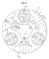
- 10 generally indicates the mandrel body, formed by a stiff front plate 11 in the shape of a bell-like disc and by a back wall 12, rigidly associated with one another by means of bolts 13.
- a cavity 14 is provided, wherein a sleeve 15 is axially sealingly slideable and is subject to control means, generally fluidodynamic means not illustrated in the figure.
- the plate 11 of the mandrel body supports three jaws 16, angularly spaced apart by 120°, which can perform a radial oscillation for gripping the workpiece and an axial positioning stroke.
- the radial gripping oscillation can be in a centripetal direction for outward gripping the workpiece, or in a centrifugal direction for inward gripping.
- the axial positioning stroke is adapted to move the workpiece and, after gripping, to make it engage by frontal contact with the rectified plane 17 of a central cover 18; all the machining dimensions of the workpiece being provided with reference to said plate.
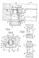
- the jaws 16 are provided at the end of corresponding supporting levers 19 which are oscillable and axially movable with respect to the plate 11 of the mandrel body. Each lever is subject to the action of a corresponding slider 20, freely slideable in a related radial seat 21 of the mandrel body.
- Each slider 20 is connected to the sleeve 15, through a positive and bidirectional inclined plane coupling 22 which converts the axial movements of the sleeve into corresponding radial movements of the slider.
- Each supporting lever 19 comprises a first spherical portion 190 for articulating said lever to the plate 11 of the mandrel body and a second hemispherical terminal portion 191 for articulating the end of the corresponding slider 20 to the lever.
- the portion 190 is accommodated in a cylindrical seat 23 of the plate 11, the internal diameter whereof is substantially equal (except for the tolerance required to avoid driving) to the equatorial diameter of said portion 190.
- the lever 19 is therefore free to rotate, without appreciable play, about the center of its own spherical portion 190 and to move axially within the cylindrical seat 23.
- the hemispherical portion 191 is in turn accommodated in a conical seat 24 of the slider 20.
- the seat 24 is provided on the surface of the slider facing the back wall 12 of the mandrel body and is connected, on its bottom, to a port 25 accommodating an intermediate portion of the lever 19, so that the portion 190 and the portion 191 of the lever are located on opposite sides with respect to the slider 20.
- said portion is truncated by a pair of parallel chordal planes 192-193 (see figs.
- the port 25 of the seat 24 is provided with two passages 26 shaped as cylinder sectors and arranged at 90° with respect to the work position of the portion 191, so that said portion is introduced with the chordal planes parallel to the line joining the passages 26 and then rotated through 90° into the work position illustrated in figures 1 and 3.
- Elastic elements 27-28 are accommodated in the cylindrical passages 26 and, reacting elastically, maintain, idling, the axial orientation of the lever 19.
- the portion 191 engages with the conical surface of the seat 24.
- This surface acts as an inclined plane and applies to the portion 191 a force F which is perpendicular (except for the friction angles) to the seat point in contact with the portion 191.
- the force F is directed upwards as illustrated in fig. 5 for a corresponding radial centrifugal movement of the slider 20, and downwards as illustrated in fig. 5a for a centripetal movement of said slider.
- the force can be resolved into a radial component R directed accordingly, and into an axial component A with a smaller value; the ratio between the radial and axial components being, for example, approximately 5:1.
- the radial component R initially causes the corresponding radial gripping oscillation of the jaw, and when this force is balanced by the reaction of the workpiece the axial component A, overcoming the component of the contact friction between the seat 24 and the portion 191 and the elastic action of a spring 29 which will be described hereafter, causes the axial positioning sliding of the lever 19.
- This sliding is limited by a stop consisting of a cylinder 30 slideably contained in a corresponding blind cylindrical seat 31 provided in the back wall 12 and pushed by the spring 29 in frontal contact engagement with the frontal wall 194 of the portion 191 of the lever 19.
- the cylinder 30 limits the axial stroke of the lever, abuttingly engaging the bottom of the corresponding blind seat 31, and thus gives the mandrel the required repeatability of its grip.
- the mandrel can indifferently perform locking and positioning of the workpiece with an outward or inward grip according to the direction of the motion of the sleeve 15.
- each lever 19 can rotate partially about its own axis, elastically in contrast with the elements 27, 28 or with equivalent elastic means, and thus allow the related so-called equalization oscillations to the clamps.
- the mandrel is also sealed tight, by virtue of the presence of gaskets, indicated at 32 and 33, which embrace both the cylindrical body of the sleeve 15 and the terminal part of the spherical portion 190 of each lever 19.
- gaskets 33 are clamped by covers 34 provided with a spherical collar 35 whereon a bush 36 is fitted, which is rigidly associated with the jaw, and is provided with a corresponding conical seat 37.
- the terminal hemispherical portion 191 of the lever 19 is arranged on the opposite side of the jaw 16 with respect to the center of oscillation of the lever, which coincides with the center of the first hemispherical portion 190. Consequently, the portion 191 acts, together with the slider 20, as a mass for compensating the centrifugal force which affects the jaw 16.
Landscapes
- Engineering & Computer Science (AREA)
- Mechanical Engineering (AREA)
- Shaping Of Tube Ends By Bending Or Straightening (AREA)
- Moulds For Moulding Plastics Or The Like (AREA)
Applications Claiming Priority (2)
| Application Number | Priority Date | Filing Date | Title |
|---|---|---|---|
| IT6753986 | 1986-07-04 | ||
| IT67539/86A IT1192814B (it) | 1986-07-04 | 1986-07-04 | Mandrino automatico autocentrante ed autostaffante |
Publications (2)
| Publication Number | Publication Date |
|---|---|
| EP0251266A2 true EP0251266A2 (fr) | 1988-01-07 |
| EP0251266A3 EP0251266A3 (fr) | 1989-10-18 |
Family
ID=11303264
Family Applications (1)
| Application Number | Title | Priority Date | Filing Date |
|---|---|---|---|
| EP87109301A Withdrawn EP0251266A3 (fr) | 1986-07-04 | 1987-06-28 | Mandrin de serrage avec centrage et positionnement automatique |
Country Status (2)
| Country | Link |
|---|---|
| EP (1) | EP0251266A3 (fr) |
| IT (1) | IT1192814B (fr) |
Cited By (8)
| Publication number | Priority date | Publication date | Assignee | Title |
|---|---|---|---|---|
| FR2720670A1 (fr) * | 1994-06-07 | 1995-12-08 | Sandvik Tobler | Mandrin de serrage à mors. |
| EP1138421A3 (fr) * | 2000-02-07 | 2003-10-01 | Howa Machinery, Ltd. | Mandrin pour machine-outil |
| EP2042254A1 (fr) * | 2007-09-27 | 2009-04-01 | SMW-Autoblok Spannsysteme GmbH | Mandrin de puissance |
| US7594665B2 (en) * | 2007-02-27 | 2009-09-29 | Illinois Tool Works Inc. | Quick-release jaws with a single-piece bearing chuck |
| US8528914B2 (en) | 2007-02-27 | 2013-09-10 | Forkardt Inc. | Quick-release jaws with single-piece bearing chuck |
| US8534677B2 (en) | 2007-02-27 | 2013-09-17 | Forkardt Inc. | Work-holding chuck with quick-release jaws |
| CN109789493A (zh) * | 2016-11-24 | 2019-05-21 | 株式会社北川铁工所 | 卡盘装置 |
| CN115741154A (zh) * | 2022-11-15 | 2023-03-07 | 山西江淮重工有限责任公司 | 用于大型半球壳体的加工装置及加工方法 |
Family Cites Families (5)
| Publication number | Priority date | Publication date | Assignee | Title |
|---|---|---|---|---|
| US3472526A (en) * | 1967-10-17 | 1969-10-14 | Woodworth Co N A | Universal power chuck |
| DE7613635U1 (de) * | 1976-04-30 | 1976-09-16 | Paul Forkardt Kg, 4000 Duesseldorf | Kraftbetaetigtes spannfutter fuer drehmaschinen |
| FR2373351A1 (fr) * | 1976-12-09 | 1978-07-07 | Tobler Meca Precision Franco S | Mandrin de serrage a mors |
| US4465289A (en) * | 1981-07-13 | 1984-08-14 | William Banks | Chuck |
| DE3322201A1 (de) * | 1983-06-21 | 1985-01-10 | RAKO Spannwerkzeuge GmbH, 7440 Nürtingen | Spannfutter fuer drehmaschinen |
-
1986
- 1986-07-04 IT IT67539/86A patent/IT1192814B/it active
-
1987
- 1987-06-28 EP EP87109301A patent/EP0251266A3/fr not_active Withdrawn
Cited By (16)
| Publication number | Priority date | Publication date | Assignee | Title |
|---|---|---|---|---|
| EP0686449A1 (fr) * | 1994-06-07 | 1995-12-13 | Sandvik Tobler S.A. | Mandrin de serrage à mors |
| US5605343A (en) * | 1994-06-07 | 1997-02-25 | Sandvik Tobler S.A. | Gripping jaw |
| FR2720670A1 (fr) * | 1994-06-07 | 1995-12-08 | Sandvik Tobler | Mandrin de serrage à mors. |
| EP1138421A3 (fr) * | 2000-02-07 | 2003-10-01 | Howa Machinery, Ltd. | Mandrin pour machine-outil |
| US8534677B2 (en) | 2007-02-27 | 2013-09-17 | Forkardt Inc. | Work-holding chuck with quick-release jaws |
| EP2114602A4 (fr) * | 2007-02-27 | 2017-05-24 | Forkardt Inc. | Mâchoires à ouverture rapide avec dispositif de serrage à roulement monobloc |
| US7594665B2 (en) * | 2007-02-27 | 2009-09-29 | Illinois Tool Works Inc. | Quick-release jaws with a single-piece bearing chuck |
| US7954825B2 (en) | 2007-02-27 | 2011-06-07 | Illinois Tool Works Inc. | Quick-release jaws with single-piece bearing chuck |
| US8746704B2 (en) | 2007-02-27 | 2014-06-10 | Forkardt Inc. | Work-holding chuck with quick-release jaws |
| US8528914B2 (en) | 2007-02-27 | 2013-09-10 | Forkardt Inc. | Quick-release jaws with single-piece bearing chuck |
| EP2042254A1 (fr) * | 2007-09-27 | 2009-04-01 | SMW-Autoblok Spannsysteme GmbH | Mandrin de puissance |
| US8251374B2 (en) | 2007-09-27 | 2012-08-28 | Smw-Autoblok Spannsysteme Gmbh | Power-operated chuck |
| JP2009083098A (ja) * | 2007-09-27 | 2009-04-23 | Smw Autoblok Spannsysteme Gmbh | 電動チャック |
| CN109789493A (zh) * | 2016-11-24 | 2019-05-21 | 株式会社北川铁工所 | 卡盘装置 |
| EP3546096A4 (fr) * | 2016-11-24 | 2019-11-06 | Kitagawa Iron Works Co., Ltd | Dispositif de mandrin |
| CN115741154A (zh) * | 2022-11-15 | 2023-03-07 | 山西江淮重工有限责任公司 | 用于大型半球壳体的加工装置及加工方法 |
Also Published As
| Publication number | Publication date |
|---|---|
| IT1192814B (it) | 1988-05-12 |
| IT8667539A0 (it) | 1986-07-04 |
| EP0251266A3 (fr) | 1989-10-18 |
Similar Documents
| Publication | Publication Date | Title |
|---|---|---|
| JP2858955B2 (ja) | マシンツールを結合するためのシステム | |
| US4655655A (en) | Tool and workpiece holding arrangement for material removing machining | |
| US7954825B2 (en) | Quick-release jaws with single-piece bearing chuck | |
| EP0251266A2 (fr) | Mandrin de serrage avec centrage et positionnement automatique | |
| KR100259551B1 (ko) | 파지력이 증가된 잠금기구를 구비한 공구유니트 클램핑장치 | |
| TWI904287B (zh) | 旋轉工具、接合裝置以及接合方法 | |
| US4976575A (en) | Tool holding system for automatic tool changing | |
| JP2018130822A (ja) | 固定具及びクランプハウジング | |
| US6655699B2 (en) | Six jaw equalizing chuck | |
| CN115552138A (zh) | 用于将夹紧卡盘连接到轴上的构件 | |
| JPH02243209A (ja) | 工作機械主軸用工具アダプタ | |
| US5820135A (en) | Counter centrifugal chuck and mounting systems | |
| US4398886A (en) | Rotatable socket for a dental handpiece | |
| EP0387228B1 (fr) | Accouplement d'outil entre un porte-outil et une broche de machine | |
| US4610155A (en) | Manufacture of article having undercut internal surface | |
| US6330737B1 (en) | Tool for mounting disk valves in motor cylinder heads | |
| EP0291477B1 (fr) | Moyens de serrage de porte-outils pour machine-outil | |
| EP0564296A1 (fr) | Appareil pour la broche principale d'une machine outil | |
| US4513980A (en) | Chuck collet | |
| JP2002543990A (ja) | 高回転速度用の締付装置 | |
| EP0400533B1 (fr) | Mandrin autocentrant avec des mors balancés | |
| JPS643606Y2 (fr) | ||
| JP2002513682A (ja) | ツール交換装置 | |
| US6276880B1 (en) | Tool interconnect structure | |
| SU1333576A1 (ru) | Групповой схват |
Legal Events
| Date | Code | Title | Description |
|---|---|---|---|
| PUAI | Public reference made under article 153(3) epc to a published international application that has entered the european phase |
Free format text: ORIGINAL CODE: 0009012 |
|
| AK | Designated contracting states |
Kind code of ref document: A2 Designated state(s): DE ES FR GB |
|
| PUAL | Search report despatched |
Free format text: ORIGINAL CODE: 0009013 |
|
| AK | Designated contracting states |
Kind code of ref document: A3 Designated state(s): DE ES FR GB |
|
| 17P | Request for examination filed |
Effective date: 19891215 |
|
| 17Q | First examination report despatched |
Effective date: 19901203 |
|
| STAA | Information on the status of an ep patent application or granted ep patent |
Free format text: STATUS: THE APPLICATION IS DEEMED TO BE WITHDRAWN |
|
| 18D | Application deemed to be withdrawn |
Effective date: 19910730 |
|
| RIN1 | Information on inventor provided before grant (corrected) |
Inventor name: BRONZINO, WALTER Inventor name: BRONZINO, PIER MAURO |