EP0251401A1 - Appareil pour épandre une matière poudreuse ou granuleuse - Google Patents
Appareil pour épandre une matière poudreuse ou granuleuse Download PDFInfo
- Publication number
- EP0251401A1 EP0251401A1 EP87201190A EP87201190A EP0251401A1 EP 0251401 A1 EP0251401 A1 EP 0251401A1 EP 87201190 A EP87201190 A EP 87201190A EP 87201190 A EP87201190 A EP 87201190A EP 0251401 A1 EP0251401 A1 EP 0251401A1
- Authority
- EP
- European Patent Office
- Prior art keywords
- tube
- outflow opening
- blade wheel
- substance
- storage holder
- Prior art date
- Legal status (The legal status is an assumption and is not a legal conclusion. Google has not performed a legal analysis and makes no representation as to the accuracy of the status listed.)
- Withdrawn
Links
- 239000000126 substance Substances 0.000 title claims abstract description 24
- 238000003860 storage Methods 0.000 claims abstract description 20
- 239000003337 fertilizer Substances 0.000 claims abstract description 4
- 238000009826 distribution Methods 0.000 claims description 7
- 238000005192 partition Methods 0.000 claims description 7
- 230000001105 regulatory effect Effects 0.000 claims description 4
- 239000002245 particle Substances 0.000 abstract description 8
- 239000000463 material Substances 0.000 description 6
- WHBHBVVOGNECLV-OBQKJFGGSA-N 11-deoxycortisol Chemical compound O=C1CC[C@]2(C)[C@H]3CC[C@](C)([C@@](CC4)(O)C(=O)CO)[C@@H]4[C@@H]3CCC2=C1 WHBHBVVOGNECLV-OBQKJFGGSA-N 0.000 description 2
- 238000000034 method Methods 0.000 description 2
- 230000008569 process Effects 0.000 description 2
- 230000007480 spreading Effects 0.000 description 2
- 238000003892 spreading Methods 0.000 description 2
- 230000004308 accommodation Effects 0.000 description 1
- 230000009471 action Effects 0.000 description 1
- 230000008901 benefit Effects 0.000 description 1
- 230000001276 controlling effect Effects 0.000 description 1
- 230000008878 coupling Effects 0.000 description 1
- 238000010168 coupling process Methods 0.000 description 1
- 238000005859 coupling reaction Methods 0.000 description 1
- 238000005520 cutting process Methods 0.000 description 1
- 230000003247 decreasing effect Effects 0.000 description 1
- 230000003467 diminishing effect Effects 0.000 description 1
- 210000005069 ears Anatomy 0.000 description 1
- 230000014759 maintenance of location Effects 0.000 description 1
- 230000007246 mechanism Effects 0.000 description 1
- 239000000843 powder Substances 0.000 description 1
- 230000001681 protective effect Effects 0.000 description 1
- 239000007921 spray Substances 0.000 description 1
- 230000002311 subsequent effect Effects 0.000 description 1
- 239000000725 suspension Substances 0.000 description 1
Images

Classifications
-
- A—HUMAN NECESSITIES
- A01—AGRICULTURE; FORESTRY; ANIMAL HUSBANDRY; HUNTING; TRAPPING; FISHING
- A01C—PLANTING; SOWING; FERTILISING
- A01C7/00—Sowing
- A01C7/08—Broadcast seeders; Seeders depositing seeds in rows
- A01C7/081—Seeders depositing seeds in rows using pneumatic means
- A01C7/084—Pneumatic distribution heads for seeders
-
- A—HUMAN NECESSITIES
- A01—AGRICULTURE; FORESTRY; ANIMAL HUSBANDRY; HUNTING; TRAPPING; FISHING
- A01C—PLANTING; SOWING; FERTILISING
- A01C15/00—Fertiliser distributors
- A01C15/04—Fertiliser distributors using blowers
Definitions
- the invention relates to a device for distributing a granular or powdery substance such as fertilizer, which device consists substantially of a storage holder for this substance having an outflow opening and one or more driven distributor members connected to this outflow opening.
- Such a device is known in many embodiments, whereby ordinarily the distributor member connects directly onto the outflow opening usually located on the underside of the storage holder, and this distributor member can be a spray nozzle driven for reciprocal swinging as well as an oscillating wheel.
- the drawback to such devices is that the distributor member lies relatively close to the ground, whereby the width of spread which can be achieved remains limited.
- a solution has been found in mounting the distributor member higher up, that is, at a level higher than the outflow opening of the storage holder. This demands additional transporting means.
- Such a proposal is described in the American patent specification 4.561.596, whereby a jack is employed as transporting means.
- Such a jack causes the problem that the housing fitted around it can become blocked, and the substance in the jack can be crushed, whereby the further drawback emerges that, each time after the drive of the device has been stopped, for example because a turn has to be made in the field, the transporting of the substance is difficult to get re-started.
- the invention has for its purpose to obviate the above stated drawbacks and provides to this end a device which is distinguished in that arranged between the outflow opening and each distributor member is a guide tube, whereby means are present for generating an air flow from the one end located at the outflow opening to the other end of the tube.
- the means generating the air flow are formed by a blade wheel at the other end of the tube. This results in a suction action in the guide tube which prevents loss of material and blockage.
- the other end of the guide tube comprises one or more sideways directed through-feed openings, whereby the blade wheel is arranged for concentric rotation around that end and these through-feed openings.
- the blade wheel is therefore also used as distributor member, since the material for distribution that is fed directly into the centre of the blade wheel is thrown outward and distributed by these same blades.
- the width of the or each through-feed opening be regulated by means of a partition which can rotate concentrically round the tube. In this way the width of the spreading pattern is determined.
- the through-feed opening can be adjusted for rotation relative to the longitudinal tube axis so that the position of the pattern of spread can thereby be determined. This is of importance when distributing substances of a different nature from one another.
- a particularly uniform feeding of the substance for distribution out of the storage holder to the guide tube is ensured by concentric accommodation of the one end of the tube in the outflow opening of the storage holder and by preferably making the passage of this outflow opening adjust necessarilyable.
- the device shown in fig. 1 consists of a storage holder 1 for a substance S stored therein, which substance can be a fertilizer, which has to be distributed over land.
- a substance S stored therein, which substance can be a fertilizer, which has to be distributed over land.
- the holder is supported via a frame 2 manufactured from tubular material, this frame being carried by means of a coupling mechanism 3 on the three-point suspension lifting device of an agricultural tractor (not shown).
- the storage holder 1 has on the underside an outflow opening 4 which can be closed off, which will be further explained below.
- an outflow opening 4 Connecting onto the underside of outflow opening 4 is a cup-like body 5, which is open at the bottom, for the supply of transporting air, this being further explained below.
- a guide tube 6 Placed centrally in the middle of storage holder 1 is a guide tube 6, of which the one, lower end emerges into the cup-like body 5.
- the tube 6 is centralized in the storage holder 1 by means of bracing bars 7.
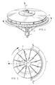
- a distributor member 8 Arranged on the other, upper end of tube 6 is a distributor member 8 which here has the form of a blade wheel, the blades 9 of which are covered at the top by a conically form ed plate 10 and on the underside by a wave shaped plate 11. As a result closed sections having radial inlet and outlet openings are created between the blades 9, see also fig. 4 and 5.
- the blade wheel 8 is non-rotatably attached to the upper end of a drive shaft 12. This attachment is carried out by means of the threaded end 13 and bolt 14 which clamps the central nave 15 of the blade wheel onto the upper end of drive shaft 12.
- Drive shaft 12 extends over the whole length of tube 6 and is mounted at the bottom in a bearing bush 13 which is accommodated in frame 2.
- the lower end of the drive shaft is formed with a conical toothed wheel 14 which co-operates with a conical toothed wheel 15.
- This toothed wheel 15 is attached to a drive shaft stump 16 which is also mounted in the bush 13.
- Stump 16 is connected via a universal joint 17 to the power take-off 18 of the agricultural tractor (not shown).
- the power take-off is enclosed by a per se known protective casing 19.
- the upper end of guide tube 6 carries a cover 20 which has a shaft portion 21 which is close fitting round tube 6 and which can rotate relative to tube 6 concentrically to its longitudinal axis.
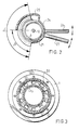
- Cover 20 displays a through-feed opening 22 which extends through a determined circular arc ⁇ , see fig. 2.
- the shaft 21 of cover 20 bears a ring 23, which serves as support for a second shaft 24, which is fitted for free rotation around the first shaft 21.
- the shaft 24 bears a curved partition 25 which can be situated in front of the through-feed opening 22 of cover 20, see also fig. 2.
- the width ⁇ of the through-feed opening 22 can therefore be adjusted with this plate 25. This is facilitated by providing each shaft 21 and 24 with a handle 26 and 27 respectively.
- the tube 6 is in addition provided with three radically directed arms 28 on the outer ends of which supports a circular arc strip 29.
- This strip 29 has a graduation with which it is possible to easily determine visually the width and direction over which the material for distribution is thrown outward.
- This strip 29 can if required contain electronic sensors or the like, whereby these values can be assessed at the central tractor driver position.
- the outflow opening of storage holder 1 is shown in top view in fig. 3.
- This outflow opening is arranged concentrically around tube 6 and consists of passages 30 arranged in a circle, whereby underneath these passages 30 is located a rotary ring 31 having a corresponding number of passages in the same pattern. By rotating this ring in a manner that is not shown but nevertheless known the passages 30 of outflow opening 4 can be more or less closed off.
- This width of spread F can be decreased by closing off the through-feed opening 22 to a greater or lesser extent using the dosage plate 25, see fig. 2.
- the gauge ring 29 can determine the required width and direction of spread using sensors, these sensors controlling for example the operation of the arms 26, 27 via the control scheme in fig. 1.
- the control scheme is a calculator unit 35 which receives as input the signals from the sensors 29 and the set-up panel 36.
- the calculator unit 35 controls a regulating unit 37 which controls the two adjusting motors 38, 39 for each of the arms 36, 37.
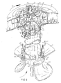
- the guide tube 6 is concentrically located in the storage holder or hopper 1, whereas the lower flange 61 is provided with holes for screw-bolts 62 for the mounting of a trumpet-like member 63, being part of the guide tube 6.
- the guide tube is provided with orifices 64 communicating with the outflow part of the hopper 1, such that the substance S can flow from the hopper 1 through the orifices 64 into the lower end of the guide tube 6.
- annular member 65 is adapted to be slided in up- and downwards direction, said member having ears 66 for connecting control rods 67, which will extend to the topside of the storage holder 1, in order to be able to full the rods upwardly or push them downwardly.
- the annular member 65 will be slided into a position, wherein the orifices 64 are partly or wholly covered by the member 65, so determining the rate of throughflow of the substance into the guide tube.
- control rods 67 can be done in any suitable way, including a manually or mechanically manner.
- the other or top end of the guide tube 6 is provided with a through-feed opening 22, formed by cutting away the side-wall of the guide tube 6 over a certain axially and radially distance.
- the top face of the tube 6 is closed off by a top plate 68, being a support for a bearing hub 69 for bearing the driving shaft 12.
- the driving shaft 12 is fixedly connected to the blade wheel 8.
- the blade wheel itself is supported by ball bearings 70, mounted in any suitable way on the central hub 69.
- the top end of the tube 6 is provided with guiding means for guiding the particles to be distributed.
- the guide means are formed by a curved plate 71, which from the bottom to the top starts from the side of the tube opposite the through-feed opening 22, to the top side of said opening 22.
- a pair of partition plates 72 are snugly fitted around the driving shaft 12, the top edge of the partition plates being in contact with the lower side of the curved plate 71, whereas the lower edge of the both plates 72 are united, such that tehy extend between the driving shaft 12 and the inner side of the tube 6.
- Further partition plates 73 are arranged underneath the curved plate 71 and partly covering the through-flow opening 22 of the tube 6.
- the plate 73 is tube-like and snugly fits into the top end of the tube 6. That tube-like plate 73 together with the curved plate 71 can be rotated with respect to the tube 6, so being able to control the inlet point of the substance to be distributed with respect to the blade wheel 8.
- the part 73 is provided with a partition means 74, a part of which is fixed to the part 73, and a part of which 74 ⁇ is formed like a flap.
- the flap 74 ⁇ is fastened to a pin 75, pivitably supported in a block 76.
- the block is fixedly secured to the part 73.
- the lower side of the pin 75 is provided with an arm 77 which can be set in one of the positions according to arrow P6. By turning the arm 77 the flap 74 ⁇ will be turned either, and together with a flap 74 ⁇ at the opposite side of the through-feed opening 22, said opening can be narrowed or widened, so determining the width of the outflow of the substance before it will be entered into the blade wheel 8.
- each blade 9 in the blade wheel 8 is curved onto the direction of rotation as given by arrow P7.
- the curved inner end will guide the flow of substance to be distributed in a better way into the sections of the blade wheel, so diminishing wear.
- the working of the embodiment according to fig. 6 is similar to the working of the embodiment according to fig. 1, in this sense that the flow of the granular or powdery substance will be carried by the air flow generated by the blade wheel 8.
- the flow is directed according to arrow P8 from the inlet lower side of the tube 6 up to the top side of the tube 6 where the flow is guided by the curved plate 71, the part 73 and the flaps 74 ⁇ , such that the width of the flow, and the direction, with respect to the blade wheel 8, is optimally performed.
- the storage holder 1 does not necessarily have to have one guide tube 6 but can for example have two or more tubes, each of which carries a distributor member on the other end.
- the distributor member does not have to be an oscillating wheel in the form of the blade wheel shown but can also be an oscillating spreader pipe. For generating the required air flow a separate fan can be employed.
- the guide tube 6 does not have to stand vertically but can assume a position deviating therefrom and can also take a curved form.
Landscapes
- Life Sciences & Earth Sciences (AREA)
- Soil Sciences (AREA)
- Environmental Sciences (AREA)
- Fertilizing (AREA)
- Nozzles (AREA)
- Filling Or Emptying Of Bunkers, Hoppers, And Tanks (AREA)
Applications Claiming Priority (2)
| Application Number | Priority Date | Filing Date | Title |
|---|---|---|---|
| NL8601629A NL8601629A (nl) | 1986-06-23 | 1986-06-23 | Inrichting voor het verspreiden van een korrel- of poedervormige stof. |
| NL8601629 | 1986-06-23 |
Publications (1)
| Publication Number | Publication Date |
|---|---|
| EP0251401A1 true EP0251401A1 (fr) | 1988-01-07 |
Family
ID=19848207
Family Applications (1)
| Application Number | Title | Priority Date | Filing Date |
|---|---|---|---|
| EP87201190A Withdrawn EP0251401A1 (fr) | 1986-06-23 | 1987-06-22 | Appareil pour épandre une matière poudreuse ou granuleuse |
Country Status (5)
| Country | Link |
|---|---|
| US (1) | US4874130A (fr) |
| EP (1) | EP0251401A1 (fr) |
| JP (1) | JPS6339654A (fr) |
| DK (1) | DK317887A (fr) |
| NL (1) | NL8601629A (fr) |
Cited By (7)
| Publication number | Priority date | Publication date | Assignee | Title |
|---|---|---|---|---|
| EP0311202A1 (fr) * | 1987-10-05 | 1989-04-12 | C. van der Lely N.V. | Epandeur de matériau comme, par exemple, engrais |
| EP0303325A3 (en) * | 1987-08-10 | 1989-05-03 | C. Van Der Lely N.V. | A machine for spreading material |
| EP0298549A3 (en) * | 1987-07-02 | 1989-07-26 | C. Van Der Lely N.V. | A machine for spreading material, such as fertilizer |
| US4874130A (en) * | 1986-06-23 | 1989-10-17 | Multinorm B.V. | Device for distributing a granular or powdery substance |
| FR2719188A1 (fr) * | 1994-04-28 | 1995-11-03 | Sulky Burel | Système d'évaluation de la densité en grains d'un flux de grains en suspension, machine et procédé d'épandage utilisant un tel système. |
| DE19620830C2 (de) * | 1995-06-17 | 2002-05-16 | Rauch Landmaschfab Gmbh | Sämaschine mit einem trichterförmigen Saatgut-Behälter |
| EP4074158A1 (fr) * | 2021-04-14 | 2022-10-19 | Amazonen-Werke H. Dreyer SE & Co. KG | Dispositif de distribution pour une machine pneumatique d'épandage agricole |
Families Citing this family (13)
| Publication number | Priority date | Publication date | Assignee | Title |
|---|---|---|---|---|
| USD427206S (en) * | 1998-08-07 | 2000-06-27 | Deere & Company | Multifaceted product tank |
| DE102010009510B4 (de) * | 2009-03-06 | 2014-07-10 | Wolfgang Folger | Streuscheibe, Streuvorrichtung und Verfahren zum Verteilen von Streugut sowie Verfahren zur Regelung der Streugutdurchflussmenge |
| AT511804B1 (de) * | 2011-11-17 | 2013-03-15 | Berndorf Band Gmbh | Vorrichtung zur herstellung einer platte aus kunststeinmaterial |
| DE102013002751A1 (de) * | 2013-02-19 | 2014-09-04 | Rauch Landmaschinenfabrik Gmbh | Verteilmaschine mit einem ihrer Verteilerscheibe zugeordneten Sensor |
| US9643800B2 (en) | 2013-02-23 | 2017-05-09 | Phillip Douglas | Horizontal support system |
| US10106338B2 (en) * | 2013-02-23 | 2018-10-23 | Phillip Allan Douglas | Material separator for a vertical pneumatic system |
| DE102016010270A1 (de) * | 2016-08-24 | 2018-03-01 | Gerald Funck | Verfahren und Vorrichtung zur Verteilung körnigen Guts auf mehrere Leitungen |
| RO135186A2 (ro) | 2018-08-10 | 2021-09-30 | Great Plains Manufacturing,Inc. | Sistem de reglare a fluxului de seminţe |
| JP2021073863A (ja) * | 2019-11-06 | 2021-05-20 | ワコーコーポレーション株式会社 | 粒状物散布装置及び移動型散布装置 |
| US11606897B2 (en) * | 2020-04-03 | 2023-03-21 | Harvest International, Inc. | Bulk seed distributor |
| USD1072001S1 (en) | 2023-02-15 | 2025-04-22 | Harvest International, Inc. | Circular bulk seed distributor |
| USD1106280S1 (en) | 2024-01-11 | 2025-12-16 | Harvest International, Inc. | Circular seed manifold |
| US20250228154A1 (en) | 2024-01-11 | 2025-07-17 | Harvest International, Inc. | Circular bulk seed distributor manifold |
Citations (7)
| Publication number | Priority date | Publication date | Assignee | Title |
|---|---|---|---|---|
| US2157630A (en) * | 1935-05-18 | 1939-05-09 | Ralph R Root | Dusting machine |
| US2923574A (en) * | 1956-09-13 | 1960-02-02 | Fuss Eric William | Distributing means with spinner for grain |
| FR1498719A (fr) * | 1966-10-06 | 1967-10-20 | Machine épandeuse par centrifugation plus particulièrement destinée à des travaux agricoles | |
| FR1554609A (fr) * | 1966-01-22 | 1969-01-24 | ||
| FR2001923A1 (fr) * | 1968-02-15 | 1969-10-03 | Amazonen Werke Dreyer H | |
| FR2036252A5 (fr) * | 1969-03-07 | 1970-12-24 | Kidd Archibald W | |
| EP0061335A1 (fr) * | 1981-03-25 | 1982-09-29 | Charles Balmer | Semoir ou distributeur pneumatique de granulés ou graines |
Family Cites Families (12)
| Publication number | Priority date | Publication date | Assignee | Title |
|---|---|---|---|---|
| US396251A (en) * | 1889-01-15 | adamson | ||
| US1253672A (en) * | 1916-05-29 | 1918-01-15 | Niagara Sprayer Company | Dusting and spraying apparatus. |
| US1644031A (en) * | 1926-12-06 | 1927-10-04 | William Z Pulliam | Centrifugal spreader |
| US2758842A (en) * | 1952-10-01 | 1956-08-14 | William M Burroff | Seed broadcaster |
| US3156473A (en) * | 1961-01-25 | 1964-11-10 | Biasi Charles P De | Material spreading spinner |
| US3165859A (en) * | 1961-10-10 | 1965-01-19 | Amchem Prod | Dry feeder spray apparatus |
| US3227461A (en) * | 1964-09-28 | 1966-01-04 | Jr William D Love | Material spreading and broadcasting device |
| SU677702A1 (ru) * | 1977-12-29 | 1979-08-05 | Украинский Научно-Исследовательский Институт Механизации Иэлектрификации Сельского Хозяйства | Пневматический высевающий аппарат |
| US4300725A (en) * | 1979-09-13 | 1981-11-17 | Moherek Edward F | Apparatus for uniformly dispensing and distributing material |
| SU880305A1 (ru) * | 1980-06-09 | 1981-11-15 | Научно-Исследовательский Конструкторско-Технологический Институт По Машинам Для Подготовки И Внесения В Почву Минеральных Удобрений | Рабочий орган разбрасывател сыпучих материалов |
| DE3446311A1 (de) * | 1984-12-19 | 1986-06-19 | Hans von der 4530 Ibbenbüren Heide | Fahrbarer wagen zum austragen von streumitteln |
| NL8601629A (nl) * | 1986-06-23 | 1988-01-18 | Multinorm Bv | Inrichting voor het verspreiden van een korrel- of poedervormige stof. |
-
1986
- 1986-06-23 NL NL8601629A patent/NL8601629A/nl not_active Application Discontinuation
-
1987
- 1987-06-22 EP EP87201190A patent/EP0251401A1/fr not_active Withdrawn
- 1987-06-22 DK DK317887A patent/DK317887A/da not_active Application Discontinuation
- 1987-06-23 JP JP62156402A patent/JPS6339654A/ja active Pending
- 1987-06-23 US US07/065,588 patent/US4874130A/en not_active Expired - Fee Related
Patent Citations (7)
| Publication number | Priority date | Publication date | Assignee | Title |
|---|---|---|---|---|
| US2157630A (en) * | 1935-05-18 | 1939-05-09 | Ralph R Root | Dusting machine |
| US2923574A (en) * | 1956-09-13 | 1960-02-02 | Fuss Eric William | Distributing means with spinner for grain |
| FR1554609A (fr) * | 1966-01-22 | 1969-01-24 | ||
| FR1498719A (fr) * | 1966-10-06 | 1967-10-20 | Machine épandeuse par centrifugation plus particulièrement destinée à des travaux agricoles | |
| FR2001923A1 (fr) * | 1968-02-15 | 1969-10-03 | Amazonen Werke Dreyer H | |
| FR2036252A5 (fr) * | 1969-03-07 | 1970-12-24 | Kidd Archibald W | |
| EP0061335A1 (fr) * | 1981-03-25 | 1982-09-29 | Charles Balmer | Semoir ou distributeur pneumatique de granulés ou graines |
Cited By (8)
| Publication number | Priority date | Publication date | Assignee | Title |
|---|---|---|---|---|
| US4874130A (en) * | 1986-06-23 | 1989-10-17 | Multinorm B.V. | Device for distributing a granular or powdery substance |
| EP0298549A3 (en) * | 1987-07-02 | 1989-07-26 | C. Van Der Lely N.V. | A machine for spreading material, such as fertilizer |
| EP0303325A3 (en) * | 1987-08-10 | 1989-05-03 | C. Van Der Lely N.V. | A machine for spreading material |
| EP0311202A1 (fr) * | 1987-10-05 | 1989-04-12 | C. van der Lely N.V. | Epandeur de matériau comme, par exemple, engrais |
| FR2719188A1 (fr) * | 1994-04-28 | 1995-11-03 | Sulky Burel | Système d'évaluation de la densité en grains d'un flux de grains en suspension, machine et procédé d'épandage utilisant un tel système. |
| EP0682857A1 (fr) * | 1994-04-28 | 1995-11-22 | Sulky-Burel S.A. | Procédé de réglage de la largeur d'épandage pour machine d'épandage de particules granulaires |
| DE19620830C2 (de) * | 1995-06-17 | 2002-05-16 | Rauch Landmaschfab Gmbh | Sämaschine mit einem trichterförmigen Saatgut-Behälter |
| EP4074158A1 (fr) * | 2021-04-14 | 2022-10-19 | Amazonen-Werke H. Dreyer SE & Co. KG | Dispositif de distribution pour une machine pneumatique d'épandage agricole |
Also Published As
| Publication number | Publication date |
|---|---|
| NL8601629A (nl) | 1988-01-18 |
| JPS6339654A (ja) | 1988-02-20 |
| DK317887D0 (da) | 1987-06-22 |
| DK317887A (da) | 1987-12-24 |
| US4874130A (en) | 1989-10-17 |
Similar Documents
| Publication | Publication Date | Title |
|---|---|---|
| US4874130A (en) | Device for distributing a granular or powdery substance | |
| US5046664A (en) | Spreader | |
| US5860604A (en) | Motorized fertilizer spreader | |
| US4280419A (en) | Pneumatic system for conveying granular material | |
| US5237803A (en) | Centrifugal combination sprayer/cutter apparatus | |
| EP0127922B1 (fr) | Epandage d'un matériau sur une surface | |
| US4609153A (en) | Device for spreading granular and/or powdery material | |
| EP0303325B2 (fr) | Epandeur | |
| EP0061335B1 (fr) | Semoir ou distributeur pneumatique de granulés ou graines | |
| US2720070A (en) | Forage crop cutting and conveying device | |
| US3730395A (en) | Seed and fertilizer spreader | |
| US5004163A (en) | Devices for spreading granular and/or powdery material | |
| US4111364A (en) | Herbicide applying machine | |
| US3443763A (en) | Granular distributor | |
| US6116526A (en) | Implement for spreading granular and/or pulverulent material | |
| EP0287165B1 (fr) | Machine pour épandre un matériau | |
| US2758842A (en) | Seed broadcaster | |
| JPH0328784Y2 (fr) | ||
| HU210649B (en) | Mixing and distribution trailer | |
| US3980236A (en) | Slinger spreader | |
| EP0117005A2 (fr) | Distributeur centrifuge | |
| US3246846A (en) | Spraying machine | |
| USRE24169E (en) | Forage crop cutting and conveying device | |
| EP0289095B1 (fr) | Epandeur centrifuge | |
| US2940209A (en) | Apparatus for distributing agricultural chemicals |
Legal Events
| Date | Code | Title | Description |
|---|---|---|---|
| PUAI | Public reference made under article 153(3) epc to a published international application that has entered the european phase |
Free format text: ORIGINAL CODE: 0009012 |
|
| AK | Designated contracting states |
Kind code of ref document: A1 Designated state(s): AT BE CH DE ES FR GB GR IT LI LU NL SE |
|
| 17P | Request for examination filed |
Effective date: 19880701 |
|
| 17Q | First examination report despatched |
Effective date: 19891220 |
|
| STAA | Information on the status of an ep patent application or granted ep patent |
Free format text: STATUS: THE APPLICATION IS DEEMED TO BE WITHDRAWN |
|
| 18D | Application deemed to be withdrawn |
Effective date: 19900501 |
|
| RIN1 | Information on inventor provided before grant (corrected) |
Inventor name: WONDERGEM, JAN |