EP0251438A2 - Verstellbarer Gasdruckregler mit festgemachter Membran - Google Patents
Verstellbarer Gasdruckregler mit festgemachter Membran Download PDFInfo
- Publication number
- EP0251438A2 EP0251438A2 EP87303583A EP87303583A EP0251438A2 EP 0251438 A2 EP0251438 A2 EP 0251438A2 EP 87303583 A EP87303583 A EP 87303583A EP 87303583 A EP87303583 A EP 87303583A EP 0251438 A2 EP0251438 A2 EP 0251438A2
- Authority
- EP
- European Patent Office
- Prior art keywords
- valve
- diaphragm
- poppet
- seat
- stem
- Prior art date
- Legal status (The legal status is an assumption and is not a legal conclusion. Google has not performed a legal analysis and makes no representation as to the accuracy of the status listed.)
- Withdrawn
Links
Images


Classifications
-
- G—PHYSICS
- G05—CONTROLLING; REGULATING
- G05D—SYSTEMS FOR CONTROLLING OR REGULATING NON-ELECTRIC VARIABLES
- G05D16/00—Control of fluid pressure
- G05D16/04—Control of fluid pressure without auxiliary power
- G05D16/06—Control of fluid pressure without auxiliary power the sensing element being a flexible membrane, yielding to pressure, e.g. diaphragm, bellows, capsule
- G05D16/063—Control of fluid pressure without auxiliary power the sensing element being a flexible membrane, yielding to pressure, e.g. diaphragm, bellows, capsule the sensing element being a membrane
- G05D16/0644—Control of fluid pressure without auxiliary power the sensing element being a flexible membrane, yielding to pressure, e.g. diaphragm, bellows, capsule the sensing element being a membrane the membrane acting directly on the obturator
- G05D16/0655—Control of fluid pressure without auxiliary power the sensing element being a flexible membrane, yielding to pressure, e.g. diaphragm, bellows, capsule the sensing element being a membrane the membrane acting directly on the obturator using one spring-loaded membrane
Definitions
- This invention relates to tied-diaphragm gas pressure regulators. More particularly, it relates to gas pressure regulators having a diaphragm connected to the valve assembly so as to obtain relatively complete valve closure even when particles that may be produced by corrosive gases are present on the valve seat.
- U.S. Patent No. 4,257,450 One prior 'art attempt to solve the above- described problems is shown in U.S. Patent No. 4,257,450.
- the subject patent describes a gas pressure regulator having a lost-motion connection to the diaphragm. Nevertheless, this construction requires a hole in the diaphragm, which may provide a path for unwanted leakage of corrosive and/or toxic gas.
- Metal-to-metal and resilient seals are provided in an attempt to cut off this unwanted leakage.
- the resilient seals are subject to deterioration through exposure to the corrosive gases. They can even serve as fuel for unwanted combustion in the regulator and a destructive condition commonly known as regulator burnout. Even the metal-to-metal seals may potentially leak.
- the subject patent also attempts to solve the misalignment problem by providing a complex mechanism including a number of parts. Both the sealing mechanism and the mechanism to accommodate misalignment are complex and therefore costly to produce.
- the invention takes the form of a tied-diaphragm gas pressure reducing regulator for reducing high-pressure gas to low pressure for various applications.
- the gas pressure regulator of the instant invention is especially useful with corrosive gases. It is also usable with other gases such as toxic and high purity gases.
- Located between the upper or cap portion of the regulator and the lower or body portion is a flexible diaphragm.
- the diaphragm is contained between a spring plate which presses against the diaphragm on one side by means of a spring plate. Motion of the diaphragm is transmitted to a valve poppet of a valve core assembly by means of a valve stem which ties the diaphragm to the valve poppet.
- the free end of the valve stem is connected to a collar which is in turn attached to the diaphragm without the necessity of a hole being made through the diaphragm. Attachment is accomplished by means of electron beam welding in a vacuum.
- the valve poppet has a spherical face in contact with a generally frustoconical valve seat of the valve assembly.
- a spherical face in contact with a generally frustoconical valve seat of the valve assembly.
- misalignment between the valve assembly and the diaphragm is also accommodated by providing a loose thread fit between the valve stem and the receiving collar.
- Further accommodation of misalignment is achieved by means of an external groove on the valve body which accommodates lateral movement of a depending skirt of the diaphragm prior to clamping the. cap to these body by means of a circumferential nut.
- Still further accommodation is accomplished by having a movable base for the valve biasing spring.
- valve poppet has an elastomeric flat seat in place of the spherical seat for enhanced performance at lower inlet pressures.
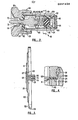
- FIG. 1 there is shown generally at 10 a tied-diaphragm gas pressure regulator.
- the regulator consists of two main subassemblies, being a hollow body 12 and a spring housing or cap 14.
- the body 12 may be made of stainless steel.
- Other parts such as cap 14 are made of brass.
- Located between the cap and body is a thin, flexible diaphragm 16 of metal material such as stainless steel.
- Diaphragm 16 is of unitary, one-piece construction. By rotating a circumferential threaded nut 18, the body 12 and cap portions 14 are held together with the diaphragm 16 therebetween.
- An adjusting screw 20 of brass material is threadedly received within an accommodating centrally disposed axial bore 22 within the end of cap 14.
- a seal 24 is contained within an enlarged threaded bore 26 on the end of cap 14. The seal is retained by means of a hollow threaded pressure nut 28 circumferentially around adjusting screw 20.
- a knob 30 of plastic material such as polypropylene is threadably secured to an end of the adjusting screw 20 by means of a pair of nuts 32, 34.
- the nuts are rotated against the pair of washers 36, 38, on opposite sides of an annular collar 40.
- a circular plastic cap 42 having a dependent skirt 44 is snap fitted within an opening 46 in one end of the knob 30.
- the cap contains therein a generally cylindrical spring chamber 48 within which is contained a coil spring 50.
- a threaded vent bore 52 at one end of chamber 48 allows access to the ambient surrounds as well as an escape path for gas or other fluid should the diaphragm 16 be ruptured in some manner.
- a conduit (not shown) may be attached at the bore 52 so that any unwanted escaping gas-may be directed to a safe location.
- Spring 50 is contained between a spring button or top plate 54 and a spring bottom plate 56, the latter of which is in operative contact with diaphragm 16.
- the frustoconi- cally shaped pressure nut 58 of adjusting screw 20 contacts spring button 54.
- a low pressure chamber 60 is contained within an open end of body 12 and is closed off by means of diaphragm 16.
- a valve core assembly generally shown at 62 is threadably secured within chamber 64 by means of a hollow threaded bushing 66 threadably secured within a bore 68 in body 12.
- a threaded end 70 of an elongated valve stem 72 is received within accommodating threads 74 within the bore 76 of the generally cylindrical collar 78.
- a threaded high pressure inlet port 80 is adapted for conducting high pressure fluid from a fluid source (not shown) into high pressure chamber 64 by means of a fluid passage 82 in the body.
- a threaded low pressure outlet port 84 conducts fluid from low pressure chamber 60 by means of passage 86 to an application of low pressure fluid (not shown).
- a pair of threaded bores 88, 90 in body 12 permit mounting of regulator 10 on a stable surface.
- valve core assembly 62 wherein all metal parts are of stainless steel consists of a generally cylindrical hollow body 92 having an opening 94 at its inlet end. Fitted within the opening is a metal mesh wire screen filter 96 serving as a.
- a lip 100 in the inlet end of body 92 is shown crimped over to retain wire screen filter 96.
- a thermoplastic base element 104 and guide 102 serve as a guide for biasing spring 105 which is located intermediate base element 102 and guide 104 as will be more fully described hereinafter.
- valve poppet 106 having a spherical sealing surface 108 seals against the generally frustoconical valve seat surface 110 of valve seat 112, which may be of plastic material. Projecting through concentric bores 114 and 116 in valve seat 112 and bushing 66, respectively, is the generally elongated valve stem 72. A post 117 on the end of the poppet opposite to the stem end has a diameter less than the diameter of the main body of the poppet 106. This post serves to retain spring 105 thereon.
- diaphragm 16 is a thin flexible member having stepped concentric surfaces 118, 120, 122 and a depending skirt 124.
- a disc-shaped member 126 is positioned on the side of diaphragm 16 opposite to the side on which collar 78 is positioned. Collar 78 and disc-shaped member 126 are fixed to diaphragm 16 by means of a circumferential weld 127 passing through disc-shaped member 126, diaphragm 16, and into annular rim 128 on collar 78.
- the weld is produced by an electron beam welding in a vacuum so that the material of disc-shaped member 126, diaphragm 16 and rim 128 are fused together.
- annular seal 130 of resilient material such as plastic is retained within a pair of concentric -annular- grooves 132, 134 surrounding the open end of body 12 so as to provide enhanced sealing.
- seal 130 may be eliminated and a metal-to-metal -seal will result. This alternative may be optionally used where it is desired to minimize the presence of potentially flammable components and thereby enhance resistance to regulator burnout.
- a circumferential groove 136 surrounds the open end and is spaced from the internal wall 138 of depending skirt 124 of diaphragm 16 so as to leave a space between the groove 136 and internal wall 138.
- diaphragm 16 may be moved over the open end of the body 12 to accommodate any misalignment of valve assembly 62 prior to clamping of nut 18, as best seen in Figure 1.
- this misalignment is the use of loose thread tolerances providing different pitch diameters for threads 70 on stem 72 and threads 140 within bore 76 of collar 78.
- Class 2A and 2B, or even lA and 1B Unified and American screw thread classes could be used.
- Still further accommodating such misalignment is the provision of a spherical surface 108 on poppet 106, sealing with frustoconical seat 110.
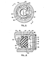
- base element 10 4 has a generally square shape with four rounded corners 142 for fitting within valve chamber 98.
- Four flat surfaces 144 are formed intermediate the four corners 142.
- Guide element 102 has a generally frustoconical surface 146 which mates with an accommodating frustoconical seat 148 within base 104.
- a counterbore 150 in guide 104 communicates with a pair of right angle cross- passages 152, 154 by way of a smaller central bore 156.
- the end of the guide element 102 opposite to its frustoconical surface 146 has a-post -158 thereon of a diameter less than that of the main body of the base element. This post serves to retain spring '105 in position and prevent its unwanted removal from the base element. Movement of the guide element 102 within base element 104 helps to adjust for misalignment. If spring 105 is out of axial alignment with the base 104 and thereby body 92, guide element 102 will move slightly within seat 148 so as to accommodate such misalignment.
- the regulator shown generally at 10 is connected to a high pressure fluid source such as a gas cylinder (not shown) by way of high pressure inlet port 80.
- a high pressure fluid source such as a gas cylinder (not shown)
- High pressure gas flows through passage 82 and into high pressure chamber 64, and thence into valve core assembly 62 through filter 96 in the end thereof.
- fluid flows through cross passages 152, 154 and around flats 144 on valve base 104 and thence into chamber 98.
- adjusting screw 20 By manually turning knob 30, adjusting screw 20 is rotated so as to force spring 50 against diaphragm 16 through spring plate 56. Movement of diaphragm 16 forces stem 72 to unseat poppet 106, which allows high pressure fluid to pass around valve seat 110 and thence into low pressure chamber 60. Fluid then flows through passage 86 and out through port 84 to an application (not shown). As the pressure increases in low pressure chamber 60, the pressure acting on diaphragm 16 counterbalances the force of spring 50 and moves it in a leftward direction, as seen in the drawing. This causes the diaphragm to pull poppet 106 closed by means of the stem 72. In this way, effects of.varying inlet pressure are mitigated, and essentially constant pressure is maintained in low pressure chamber 60 regardless of inlet pressure.
- valve core assembly structure is numbered with a three digit number beginning with a "2.”
- valve core assembly shown generally at 262 is threadably secured within chamber 64 by means of a hollow threaded bushing 266.
- the bushing is threaded into bore 68 in body 12.
- a threaded end 270 of an elongated valve stem 272 is received within accommodating threads 74 within the bore 76 of generally cylindrical collar 78.
- valve core assembly 262 wherein all metal parts are of stainless steel, has a generally cylindrical hollow body 292 having an opening 294 at its inlet end. Fitted within the opening is a metal mesh wire screen filter 296. A lip 200 is shown crimped over to retain filter 296. A thermoplastic damping element 202 is contained within thermoplastic base 204. The damping element, in turn, has a centrally disposed bore 205 therein for slidably receiving a shaft 217 projecting from the inlet end of valve poppet 206.
- the valve poppet 206 includes a circular valve seat 219 having a centrally disposed hole 221 therethrough.
- Valve seat 219 is retained on the generally cylindrical body 223 of poppet 206 by means of an annular rim 225 around valve stem 272 intermediate -its ends.
- the valve stem is threadedly secured within a bore 227 in head 223.
- a hex-shaped generally cylindrical cap 229 having an open end 231 for receiving head 223. It also has a closed end 233 having a centrally disposed hole 235 therein.
- valve seat By threadedly advancing both cap 229 and valve stem 272, the valve seat may be made to produce an annular bulge 237 having a curved surface thereon which is of a diameter to correspond with an annular lip 239 of bushing 266.
- the valve poppet 206 is biased by means of a coil spring 205 which extends between damping element 202 and head 223.
- the valve seat is preferably of an elastomeric material that resist corrosion and erosion by the gas being regulated.
- One such material is the Kalrez elastomeric material produced by Dupont Company.
- valve core assem- b l y The operation of the subject valve core assem- b l y is similar to that of the first described embodiment in that high pressure fluid is admitted therein through inlet opening 294. Fluid then passes through cross passages 252, 254 and around flats (not shown) on the exterior of guide 204. These flats may be like those numbered 104 in the first embodiment. Fluid then flows through valve chamber 298 and around valve poppet 206.
- cap 229 is hex shaped so as to provide flats 241 allowing for flow of fluid through the passages formed by the flats and the interior wall of valve chamber 298.
Landscapes
- Physics & Mathematics (AREA)
- Fluid Mechanics (AREA)
- General Physics & Mathematics (AREA)
- Engineering & Computer Science (AREA)
- Automation & Control Theory (AREA)
- Control Of Fluid Pressure (AREA)
Applications Claiming Priority (6)
| Application Number | Priority Date | Filing Date | Title |
|---|---|---|---|
| US87856986A | 1986-06-25 | 1986-06-25 | |
| US878569 | 1986-06-25 | ||
| US89741786A | 1986-08-18 | 1986-08-18 | |
| US897417 | 1986-08-18 | ||
| US904346 | 1986-09-05 | ||
| US06/904,346 US4719940A (en) | 1986-08-18 | 1986-09-05 | Adjustable tied-diaphragm gas pressure regulator |
Publications (2)
| Publication Number | Publication Date |
|---|---|
| EP0251438A2 true EP0251438A2 (de) | 1988-01-07 |
| EP0251438A3 EP0251438A3 (de) | 1989-06-07 |
Family
ID=27420494
Family Applications (1)
| Application Number | Title | Priority Date | Filing Date |
|---|---|---|---|
| EP87303583A Withdrawn EP0251438A3 (de) | 1986-06-25 | 1987-04-23 | Verstellbarer Gasdruckregler mit festgemachter Membran |
Country Status (1)
| Country | Link |
|---|---|
| EP (1) | EP0251438A3 (de) |
Cited By (1)
| Publication number | Priority date | Publication date | Assignee | Title |
|---|---|---|---|---|
| EP0332389A1 (de) * | 1988-03-08 | 1989-09-13 | National Research Development Corporation | Druckregler |
Family Cites Families (9)
| Publication number | Priority date | Publication date | Assignee | Title |
|---|---|---|---|---|
| NL299962A (de) * | ||||
| US2212709A (en) * | 1936-12-05 | 1940-08-27 | Marvin H Grove | Fluid flow regulator |
| US2294314A (en) * | 1940-02-09 | 1942-08-25 | Edwin W Mckinley | Stem connection for fluid pressure regulators |
| US2979067A (en) * | 1953-09-21 | 1961-04-11 | Maxitrol Co | Pressure regulator |
| US3149828A (en) * | 1962-02-13 | 1964-09-22 | Penn Controls | Adjusting device for pressure regulator valve |
| GB1364271A (en) * | 1970-08-17 | 1974-08-21 | Honeywell Inc | Gas pressure regulators |
| AU469414B1 (en) * | 1971-02-03 | 1972-08-10 | Ee. Jeavons & Co. Ltd | Improvements relating to diaphragm operated fluid flow |
| US4257450A (en) * | 1979-06-01 | 1981-03-24 | Veriflo Corporation | Pressure-reducing regulator valve for high-pressure gases |
| GB2156496B (en) * | 1981-04-15 | 1986-02-05 | Dereve | Fluid pressure governor |
-
1987
- 1987-04-23 EP EP87303583A patent/EP0251438A3/de not_active Withdrawn
Cited By (3)
| Publication number | Priority date | Publication date | Assignee | Title |
|---|---|---|---|---|
| EP0332389A1 (de) * | 1988-03-08 | 1989-09-13 | National Research Development Corporation | Druckregler |
| WO1989008879A1 (en) * | 1988-03-08 | 1989-09-21 | National Research Development Corporation | Pressure regulators |
| US5042697A (en) * | 1988-03-08 | 1991-08-27 | National Research Development Corporation | Pressure regulators |
Also Published As
| Publication number | Publication date |
|---|---|
| EP0251438A3 (de) | 1989-06-07 |
Similar Documents
| Publication | Publication Date | Title |
|---|---|---|
| US4719940A (en) | Adjustable tied-diaphragm gas pressure regulator | |
| US5586569A (en) | Pneumatic pressure regulator | |
| US4793379A (en) | Supply cylinder shut-off and flow control valve | |
| US4694848A (en) | Flow control valve | |
| US4718448A (en) | Gas valve | |
| US5383646A (en) | Diaphragm control valve | |
| US4346611A (en) | Insertion regulator for pressurized pipelines | |
| US4471802A (en) | Pressure regulator assembly with improved cartridge | |
| US6062245A (en) | Gaseous fuel burner manifold with integral pressure regulator assembly | |
| US3211174A (en) | Pressure relief or blowdown valve | |
| US4257450A (en) | Pressure-reducing regulator valve for high-pressure gases | |
| US4754778A (en) | Velocity boost body with wrap-around pitot tube | |
| US4237920A (en) | Spring loaded plug valve | |
| US4231549A (en) | Valve stem and valve disc connection for a diaphragm valve | |
| GB2186667A (en) | Supply cylinder shut-off and flow control valve | |
| JPH075932A (ja) | 流体圧力調整用弁組立体 | |
| US5865423A (en) | High flow diaphragm valve | |
| CN100420891C (zh) | 流体压力控制装置的阀杆密封件的保持器锁紧螺母 | |
| US6805328B2 (en) | Shut-off valve apparatus | |
| EP0059599A1 (de) | Ventilmechanismus für die Anwendung bei tiefen Temperaturen | |
| US20030056830A1 (en) | Back pressure valve with dynamic pressure control | |
| US4898204A (en) | Low pressure gas regulator | |
| US4513779A (en) | Metering valve | |
| EP0251438A2 (de) | Verstellbarer Gasdruckregler mit festgemachter Membran | |
| US5632466A (en) | Piston actuated pressure reducing valve |
Legal Events
| Date | Code | Title | Description |
|---|---|---|---|
| PUAI | Public reference made under article 153(3) epc to a published international application that has entered the european phase |
Free format text: ORIGINAL CODE: 0009012 |
|
| AK | Designated contracting states |
Kind code of ref document: A2 Designated state(s): DE FR GB IT |
|
| PUAL | Search report despatched |
Free format text: ORIGINAL CODE: 0009013 |
|
| AK | Designated contracting states |
Kind code of ref document: A3 Designated state(s): DE FR GB IT |
|
| 17P | Request for examination filed |
Effective date: 19891128 |
|
| STAA | Information on the status of an ep patent application or granted ep patent |
Free format text: STATUS: THE APPLICATION IS DEEMED TO BE WITHDRAWN |
|
| 18D | Application deemed to be withdrawn |
Effective date: 19901103 |
|
| RIN1 | Information on inventor provided before grant (corrected) |
Inventor name: BEAVERS, MICHAEL E. |