EP0251468A2 - Module d'entraînement magnétostrictif - Google Patents
Module d'entraînement magnétostrictif Download PDFInfo
- Publication number
- EP0251468A2 EP0251468A2 EP87304440A EP87304440A EP0251468A2 EP 0251468 A2 EP0251468 A2 EP 0251468A2 EP 87304440 A EP87304440 A EP 87304440A EP 87304440 A EP87304440 A EP 87304440A EP 0251468 A2 EP0251468 A2 EP 0251468A2
- Authority
- EP
- European Patent Office
- Prior art keywords
- stack
- disks
- drive
- magnetostrictive
- drive module
- Prior art date
- Legal status (The legal status is an assumption and is not a legal conclusion. Google has not performed a legal analysis and makes no representation as to the accuracy of the status listed.)
- Granted
Links
Images


Classifications
-
- H—ELECTRICITY
- H10—SEMICONDUCTOR DEVICES; ELECTRIC SOLID-STATE DEVICES NOT OTHERWISE PROVIDED FOR
- H10N—ELECTRIC SOLID-STATE DEVICES NOT OTHERWISE PROVIDED FOR
- H10N35/00—Magnetostrictive devices
-
- B—PERFORMING OPERATIONS; TRANSPORTING
- B06—GENERATING OR TRANSMITTING MECHANICAL VIBRATIONS IN GENERAL
- B06B—METHODS OR APPARATUS FOR GENERATING OR TRANSMITTING MECHANICAL VIBRATIONS OF INFRASONIC, SONIC, OR ULTRASONIC FREQUENCY, e.g. FOR PERFORMING MECHANICAL WORK IN GENERAL
- B06B1/00—Methods or apparatus for generating mechanical vibrations of infrasonic, sonic, or ultrasonic frequency
- B06B1/02—Methods or apparatus for generating mechanical vibrations of infrasonic, sonic, or ultrasonic frequency making use of electrical energy
- B06B1/06—Methods or apparatus for generating mechanical vibrations of infrasonic, sonic, or ultrasonic frequency making use of electrical energy operating with piezoelectric effect or with electrostriction
- B06B1/0607—Methods or apparatus for generating mechanical vibrations of infrasonic, sonic, or ultrasonic frequency making use of electrical energy operating with piezoelectric effect or with electrostriction using multiple elements
- B06B1/0611—Methods or apparatus for generating mechanical vibrations of infrasonic, sonic, or ultrasonic frequency making use of electrical energy operating with piezoelectric effect or with electrostriction using multiple elements in a pile
- B06B1/0618—Methods or apparatus for generating mechanical vibrations of infrasonic, sonic, or ultrasonic frequency making use of electrical energy operating with piezoelectric effect or with electrostriction using multiple elements in a pile of piezo- and non-piezoelectric elements, e.g. 'Tonpilz'
-
- B—PERFORMING OPERATIONS; TRANSPORTING
- B06—GENERATING OR TRANSMITTING MECHANICAL VIBRATIONS IN GENERAL
- B06B—METHODS OR APPARATUS FOR GENERATING OR TRANSMITTING MECHANICAL VIBRATIONS OF INFRASONIC, SONIC, OR ULTRASONIC FREQUENCY, e.g. FOR PERFORMING MECHANICAL WORK IN GENERAL
- B06B1/00—Methods or apparatus for generating mechanical vibrations of infrasonic, sonic, or ultrasonic frequency
- B06B1/02—Methods or apparatus for generating mechanical vibrations of infrasonic, sonic, or ultrasonic frequency making use of electrical energy
- B06B1/08—Methods or apparatus for generating mechanical vibrations of infrasonic, sonic, or ultrasonic frequency making use of electrical energy operating with magnetostriction
- B06B1/085—Methods or apparatus for generating mechanical vibrations of infrasonic, sonic, or ultrasonic frequency making use of electrical energy operating with magnetostriction using multiple elements, e.g. arrays
Definitions
- This invention relates to transducers for the transmission of sonic energy and more particularly to a self-biased transducer having drive stacks comprised of interleaved high remanent flux magnets and high-strain magnetostrictive material for producing sonic energy of high power and with high performance.
- Magnetostrictive lanthanide alloys such as Terfenol-D (i.e. Tb .3 Dy .7 Fe 1.9 ), are capable of producing over five times the rms strain developed by the most competitive piezoceramics and ten times the rms strain developed by the most competitive non-lanthanide (i.e. nickel) magnetostrictive alloys. Since the acoustic output power generated by an underwater transducer is proportional to the square of the strain, this can result in a large advantage in power producing capability.
- lanthanides such as Terfenol-D have lower sound speeds than non-lanthanide magnetostrictive alloys and piezoceramics and posess seventeen times the thermal conductivity of piezoceramics such as lead-ziconate-titanate-8.
- the low sound speed tends to improve bandwidth and lowers resonance frequency, while the high thermal conductivity tends to improve power handling ability and increases attainable duty cycle.
- the degree to which these advantages can be adequately exploited depends upon overcoming several problems which arise in transducer design because of certain intrinsic properties of the lanthanide material.
- Terfenol-D has a relative permeability of only four or five, at least an order of magnitude lower than magnetostrictive nickel alloys.
- relatively short lengths of the material are used.
- the combination of low permeability and low length-to-diameter ratio of the Terfenol-D rods resulted in non-uniform bias and drive fields in prior-art transducer designs which led to utilization of only a portion of the material and non-uniform strain in the material. Demagnetization effects and fringing flux tend to increase leakage inductance and degrade transducer coupling.
- the low length-to-diameter ratio also leads to stray flux finding its way into metallic transducer components where eddy currents and hysteresis losses lower conversion efficiency.
- Terfenol-D and the other lanthanide alloys require a polarizing field because they are magnetically soft and retain insufficient remanent fields for linear operation.
- the polarizing field may be supplied by either a coil carrying direct current or permanent magnets.
- DC current is used to supply the bias field, it may be superimposed on the AC drive coil or may be carried on a separate coil. If separate AC and DC power supplies are employed and the currents are superimposed in one coil, a large choke is required to pass DC and avoid driving the DC supply with the AC power source. Also, a large condenser is required to pass AC and block DC current from entering the AC supply. If separate windings carry AC and DC, the requirement for the condenser is removed, but a large burdensome choke in series with the DC current winding is still required since the two coils will be coupled due to the transformer action of two concentric coils magnetically linked by a common core.
- the alternative to direct current biasing is biasing with permanent magnets.
- the cost of permanent magnet biasing is usually decreased AC efficiency, decreased transducer coupling, and overall reduced transducer performance.
- the AC efficiency is normally reduced because the permanent magnets also have very low permeabilities and therefore increase the reluctance of the magnetic circuit.
- greater magnetomotive force greater AC drive current
- the permanent magnet material may have to be shielded with sheet metal to avoid demagnetizing the permanent magnets with the AC drive field.
- a magnetostrictive transducer and its drive modules fabricated from interleaved permanent magnet disks and high strain magnetostrictive material disks to form a stack of such interleaved materials.
- Two such stacks in side-by-side relationship have their series-aiding magnetic circuit completed through high permeability flux return pole pieces.
- Each stack is surrounded by an electrical solenoid which provides a substantially uniform alternating field within its respective stack.
- Each stack has longitudinally extending planar cuts which are substantially parallel to the AC field in each stack produced by the solenoid. These planar cuts reduce eddy current loss within the stacked materials.
- the lux return pole pieces are laminates of thin sheets of high permeability steel which are electrically insulated from one another to likewise reduce eddy current loss resulting from the AC field.
- the steel sheets are constrained by a non-magnetic end-block into which the steel sheets are inserted and bonded.
- the mating surfaces of the pole pieces and the stacks are ground flat and smooth so that minimum air gaps exist at their juncture. Excitation of the solenoids is phased to cause each stack to expand and contract in unison to produce relative motion of the end pieces.
- the outermost surfaces of the end blocks are in contact with the piston masses of the transducer of which the module is a driving element.
- the piston masses and the end blocks are ground flat so that good contact is made between them.
- the magnetic disks are made of a magnetic material which provides high magnetic flux and whose remanent flux is resistant to the magnetomotive force of the applied AC magnetic field. Samarium cobalt has been found suitable for this application.
- the magnetostrictive disks are typically made of a lanthanide material, Terfenol-D being preferred which has high strain per unit AC magnetomotive force.
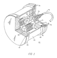
- FIG. 1 shows an isometric view in partial cross-section of a tonpilz transducer 60 constructed using the drive modules 10 of this invention.
- the transducer 60 comprises a headmass 61 (typically aluminum) and a tailmass 62 (typically stainless steel) each of which have recesses 63, 64, respectively into which the end blocks 5 of the module 10 are recessed. Only two modules 10 are shown in FIG. 1. However, it should be understood that as many modules as can be accomodated in the space within transducer 60 may be used.
- a tie rod/belleville spring assembly 65 applies a compressive force between the headmass 61 and tailmass 62 to place the module 10 under the desired compressive force.
- a shroud 66 connected to the headmass 61 by a vulcanized rubber seal 67, is attached to shell 68.
- the tailmass 62 is also in contact with shell 68 through a pressure release material 69 which is in compression from threaded ring 70 which is threaded into the shell 68.
- a back plate 71 containing a connector assembly 72 is connected to the housing 68 to form a waterproof seal therewith.
- the cavity 73 formed by the back plate 71 and the tailmass 62 provides space for an electrical tuning network (not shown) and the electrical connection of the modules 10 to the wires of cable 74 through the connector 72.
- the wires in cable 74 comprise the alternating current power wires for energizing the modules 10 from a transmitter (not shown) and which may also be used for carrying signals detected by the modules 10 to a receiver (not shown).
- the back plate 71 forms a watertight seal with the housing 68 because of the sealing material 75 which is in compression between the periphery of back plate 71 and the housing 68 provided by the tensioning of screws 76.
- the interior of the transducer 60 is thus a watertight enclosure in which the modules 10 can be electrically actuated to produce movement of the headmass 61 relative to the tailmass 62.
- the drive module 10 is acoustically coupled to the mechanical load provided by the headmass 61 and tail mass 62 by means of greased coupling joints provided by the recess 63 into which the shell end block 5 is closely fitted.
- the mating surface of the shell end block 5 and the bottom of the groove 63 are made smooth and flat so that there is good mechanical contact between these mating parts.
- These coupling joints are kept in compression by the mechanical pre-stress system comprising the tie rod assembly 65 in which rod 650 is threaded into the headmass 61 and which is tensioned by the nut 651 compressing belleville spring 652 against the tailmass 62.
- the easily machined shell block 5/pole piece 4 assembly 7 of module 10 facilitates this type of mechanical coupling.
- the modular design makes the drive assembly comprising modules 10 easily replaceable in the event of failure of any module.
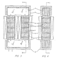
- FIGS. 2-5 there are shown an isometric view, two cross-sectional views, and an exploded view, respectively, of one embodiment of a magnetostrictive drive module 10 constructed in accordance with this invention.
- FIGS. 3 and 4 are sectional views taken along section lines I-I and II-II of FIGS. 4 and 3, respectively.
- Two magnetostrictive stacks 11 are provided for the module 10.
- Each stack 11 comprises interleaved laminated disks of magnetostrictive material 1 and laminated disks of permanent magnets 2.
- Each stack 11 is substantially enclosed except for its ends by a coil 3 which is connected to a source of alternating current (not shown) for providing alternating magnetomotive force to each stack 11.
- the permanent magnets 2 in each stack 11 have the same direction of magnetization and are arranged so that the stacks 11 are poled in opposite N,S directions as shown in FIG. 3.
- the magnetic path is completed by causing the ends 110 of stacks 11 to be in contact with pole pieces 4 thereby completing the magnetic circuit comprising stacks 11 and pole pieces 4.
- the pole pieces 4 comprise a stack of 2 mil laminations of SiFe steel sheets. These pole pieces 4 are contained within a shell end block 5, typically of aluminum or stainless steel, and secured within said end block 5 by structural epoxy 6, such as commercially available type A-2/E.
- the drive coils 3 are wound with high temperature magnet wire, typically number 18 AWG insulated magnet wire.
- the space between a stack 11 and the coil 3 is filled with silicone rubber 8.
- the stac 11 is wrapped with silicone tape (such as commercially available Moxness tape) prior to the preceding step and assembly into the module 10.
- silicone tape such as commercially available Moxness tape
- the silicone rubber serves to decouple the coil 3 from the stack 11, which vibrates when the coil 3 is driven with alternating current.
- the silicone rubber 8 also serves to insulate the stack from the coil, to support the coil, and to improve thermal conduction from the coil to the stack.
- the stacks 11 of interleaved magnetostrictive material 1 and permanent magnet material 2 comprises stacks of laminated disks of Terfenol-D (or other lanthanide drive material) interleaved with laminated disks of samarium cobalt permanent magnets 2.
- the samarium cobalt magnets have the property of having high energy product with high intrinsic coercivity such that the magnet is not demagnetized, but maintains a stable direct magnetic field in the magnetic circuit comprising stacks 11 and pole pieces 4 in spite of large AC drive fields and high temperatures within the stack 11 produced by the coils 3.
- the magnetic circuit is completed by the pair of return paths provided by the pole pieces 4 which consist of low loss, high permeability, laminated silicon iron, ⁇ r approximately equal to 104, or similar ferromagnetic material.
- the laminations 15 are electrically insulated from one another by insulating varnish 16 as in conventional transformer design technology and the laminations are very thin (1 or 2 mils thickness).
- the laminations 15 are oriented such that they are in the same direction as the magnetic flux of the magnetostrictive stacks.
- pole piece 4 which is mechanically very rigid in the direction of longitudinal vibration produced by the Terfenol-D material 1 and serves to enhance thermal conduction from the magnetostrictive stacks 11 to the end blocks 5.
- Heat is conducted from the end blocks 5 to head mass 61 and tail 62 mass components of a transducer 60 (shown in FIG. 1).
- the head mass when in operation, is in thermal contact with sea water.
- the aluminum (or nonmagnetic stainless steel) hollow end blocks 5 serve as shells into which the silicone iron laminations 15 are cemented into place with structural epoxy 6.
- the resulting pole piece/end block assembly 7 has nearly the same structural rigidity as a solid block of metal.
- the self-biased magnetostrictive stack 11 shown in isometric view in FIG. 5 is fabricated by initially longitudinally cutting with a diamond saw substantially equal diameter cylindrical rods of Terfenol-D and unmagnetized samarium cobalt into slabs 13, 14, respectively of approximately one-quarter-inch thickness. Each slab has plane parallel faces produced by the cut.
- the Terfenol-D and samarium cobalt slabs 13, 14 are each reassembled to form slightly elliptical rods using an electrical insulative adhesive 19 such as commercially available General Electric Type 7031. The reassembled rods are then cut into disks 1 of Terfenol-D and disks 2 of samarium cobalt.
- Disks of Terfenol-D are interleaved with disks of samarium cobalt and are cemented together with structural epoxy 6, typically commercially available Type A-2/E, under 100-200 pounds of pressure which provides a one mil thick film of epoxy 6 bonding the disks 1, 2 to thereby form stack 11.
- the maximum thickness of the slabs of Terfenol-D and samarium cobalt is determined by allowable eddy current losses.
- the allowable thickness is relatively thick ( ⁇ 0.25 inches) relative to that of steel laminations ( ⁇ 1-2 mils) in the pole pieces 4, which have a much higher permeability.
- Reduction of eddy currents has the desirable effect of reducing the eddy current I2R losses and also reducing the opposing magnetomotive force of the non-uniform eddy currents which in turn causes a non-uniform flux density.
- the number of slabs, their dimensions, and their placement are determined by an optimization procedure using a finite difference numerical computer program which solves Maxwell's equations and determines the magnetic field distribution throughout the magnetic circuit.
- the design of the self-biased drive module 10 is optimized with respect to leakage inductance, the amount of fringing flux, AC and DC magnetic field strengths, and field uniformities throughout the magnetic circuit. Since permeability and optimum DC bias points in lanthanide magnetostrictive materials are a function of applied stress, the values for incremental permeabilities for the entire range of expected stress conditions in the transducer are utilized in the optimization process.
- the AC and DC fields in a self-biased lanthanide magnetostrictive stack 11 with distributed samarium cobalt magnets 2 can be made very uniform when combined with the high permeability return paths in the magnetic circuit of the pole pieces 4.
- the magnetostrictive stacks 11 Prior to being placed in the magnetic circuit, the magnetostrictive stacks 11 are placed in a strong magnetic field (approximately 150 kG) to fully magnetize the interleaved samarium cobalt disks 2.
- the self-biased stacks 11 are fitted with the high temperature magnet wire drive coils 3 prior to being joined with the pole pieces 4 by the above-mentioned structural epoxy 6 to form the module 10.
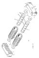
- FIG. 5 is an exploded view showing the drive module 10 components for a typical drive module.
- a drive module 10 comprises a two-leg closed-path magnetic circuit. Magnetic flux generated by alternating current excitation of the solenoids 3 passes through the magnetic circuit comprising the solenoid enclosed Terfenol/samarium cobalt drive stacks 11, typically 3 to 6 inches long and 1 inch or more in diameter, through a glass fiber disks 17, typically 6 mil thick type G10 glass fiber reinforced resin, and high permeability pole pieces 4, typically 2 mil laminations of silicon iron.
- the disks 17, 17 ⁇ are optional, bit if used, serve to insulate the stacks 11 from the head and tail masses 61, 62 which may be in contact with water when transducer 60 is in use.
- Each drive coil 3 consists typically of 700 to 1400 turns of number 18 gauge high temperature magnet wire.
- the drive coils 3 are wired so that the flux generated by each is in the series aiding direction around the magnetic circuit.
- the module design ensures near uniform AC and DC field distributions and minimizes demagnetization and leakage effects.
- the silicon iron pole piece laminations 4 are cemented to nonmagnetic end blocks 5 by a structural epoxy 6 (not shown in FIG. 5).
- the end blocks 5 have polished external surfaces 50 on their ends which enable them to be acoustically coupled to the head and tail masses 61, 62 of FIG. 1 by a grease joint of high temperature grease 51 between each of the end surfaces 50 and recesses 63, 64 of masses 61, 62, respectively.
- Typical dimensions in a stack 11 for the Terfenol-D material 1 would be one-inch diameter disks, .55 inches in length for the four innermost disks and .275 inches in length for the two outermost disks of each stack 11 of FIGS. 3-5.
- the samarium cobalt permanent magnet disks 2 of FIG. 1 are typically .150 inches in length.
- Each slab is one-quarter-inch in thickness measured in the direction transverse to the long dimension of the stack 11.
- the polarity of the self-biased magnetostrictive stacks 11 are such that the north pole of one stack and the south pole of the second stack are cemented to the same end block/pole piece assembly 7 in order to avoid bucking fields.
- the north and south field polarities are shown in FIG. 3.
- the drive coils 3 are wired such that they both circulate the AC flux in the same direction through the magnetic circuit when energized either in parallel or in a series electrical connection.
- the polarizing DC flux travels upward in one stack 11 and downward in the remaining stack 11 of the module 10, and the AC flux follows the same path but reverses direction for each direction of reversal of the alternating current excitation of the coils 3.
- the modules 10 when tested as drive elements in transducers, resulted in overall efficiencies several times greater than those normally obtained in lanthanide-driven devices of the noninterleaved type of the prior art.
- the measured AC efficiencies compare very favorably with the best AC efficiencies (i.e. DC losses ignored) obtained in the most advanced prior art direct current-biased magnetostrictive transducers and in piezoelectric transducers.
- These desirable results provided by the inventive structure are a direct consequence of distributing the samarium cobalt disks throughout the Terfenol-D stack and using the low reluctance return paths of the pole pieces 4. This technique results in highly uniform AC and DC fields and full utilization of the Terfenol-D drive material.
- the unshielded samarium cobalt magnets 2 have been subjected to high drive AC magnetic fields in modules 10 constructed in accordance with the invention for extended periods of time with no degradation in the DC magnetic field supplied by the magnets or in measured transducer performance. Since the samarium cobalt magnet disks 2 do not require shielding, the losses due to eddy currents generated in the prior art shield are eliminated in the embodiments of FIGS. 3-5.
- the self-biased drive module 10 completely eliminates the need for a direct current polarizing field and its associated losses as is common in the embodiments of the prior art.
- the direct current induced thermal burden that is normally placed on the direct current biased transducer of the prior art and the accompanying transmission cable losses are also eliminated.
- the distributed permanent magnet assembly of module 10 with its low reluctance return path virtually eliminates AC and DC stray flux external to the magnetic path of the module thereby resulting in a negligible magnetic signature and making the self-biased transducer containing such modules 10 virtually undetectable.
- FIG. 6 shows in cross-section a drive module 50 which is an alternate embodiment of the module 10 shown in FIGS. 2-5.
- the slight increase in length of the magnetostrictive drive stack 11 of module 10, because of the insertion of the permanent magnets 2, can be reduced somewhat as in module 50 by placing two of the biasing magnets 2 ⁇ in the pole piece/end block assembly 7 as shown in FIG. 6.
- the disks of Terfenol-D magnetostrictive material 1 are all of equal length and the number of permanent magnet disks 2 have been reduced by one in each stack 11 ⁇ , the total number of permanent magnet disks 2, 2 ⁇ being the same as that in module 10.
- the magnetic polarity of the permanent magnets 2, 2 ⁇ is series-aiding just as in the module 10.
- Module 50 although being slightly shorter in length than module 10 because of the placement of permanent magnets 2 ⁇ between the two sections 4 ⁇ of the pole piece 4, results in increased leakage flux between the two sections 4 ⁇ .
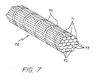
- FIG. 7 An alternative form of the drive stack 11 of FIG. 3 is shown as drive stack 70 of FIG. 7.
- the magnetostrictive drive elements 71 were fabricated from hexagonal rods of zone-melted grain-oriented Terfenol-D.
- the grain orientation in the material results in higher permeability, higher longitudinal coupling factor, higher compliance, and lower sound speed.
- the method used to obtain grain orientation is a free-standing zone-melting technique that limits the maximum diameter of the Terfenol-D rods to about 3/10 inch.
- a high packing factor and large cross-sectional area of material enclosed by a single coil is obtained by using many component rods 72 as shown in FIG. 7.
- the 0.3 inch diameter grain oriented rods were machined into hexagonal cross-section (0.25 inch across that flats) and bonded together with electrical insulative adhesive 73.
- the use of electrical insulative adhesive is important in order to electrically isolate the rods from each other, thereby limiting the orbital diameters of eddy currents to approxmately 0.25 inches.
- the bundle of adhered rods formed by the adhesive are cut into disks 71.
- the disks 71 are interspersed with the samarium cobalt disks 74, which were prepared as in the drive stack 11. Disks 71, 74 are bonded to each other to form an alternative form of magnetostrictive stack 70.
- Fabrication of the stack from large diameter round rods producing drive stacks 11 as shown in FIGS. 3-5 are preferred over the hexagonal-bar form of stack 70 because they are cheaper, and because it is more difficult to fabricate a coil 3 with an internal diameter which minimizes the air space between the coil 3 and the stack 70 than it is when the stack is substantially round as is stack 11. A close fit is desired in order to reduce leakage inductance of the coil 3.
- the magnetostrictive alloys of the lanthanide series possess advantages over competing drive materials for low-frequency applications.
- the degree to which these advantages can be exploited is determined by the extent to which engineering problems arising from the intrinsically low permeability associated with the lanthanide materials can be overcome.
- the term "lanthanide” refers to the lanthanide series of elements (lanthanum, atomic number 57, is the first in the series), several of which (Sm, Tb, Dy, Ho, Er, and Tm) in the form of alloys display extraordinary magnetostriction.
- lanthanide is to be preferred.
- the highly magnetostrictive nature of these lanthanide elements and the development of lanthanide alloys which produce large magnetostrictions at normal operating temperatures has resulted in at least one presently preferred lanthanide alloy, Terbium-Dysprosium-Iron alloy, i.e., Tb 0.3 DY 0.7 Fe 1.9 (Terfenol-D).
- Terfenol-D is capable of producing over 5 times the rms strain developed by the most competitive piezoceramics, and over 10 times the rms strain developed by the most competitive non-lanthanide (i.e. nickel) magnetostrictive alloys. Since the acoustic output power generated by an underwater projector or transducer is proportional to the square of the strain, lanthanide-driven transducers result in a large advantage in power producing capability.
- Terfonol-D has a sound speed that is roughly 60 percent that of piezoceramic and possesses about 17 times the thermal conductivity. The low sound speed tends to improve bandwidth and lowers resonance frequency, while the high thermal conductivity tends to improve power handling capability and increases attainable duty cycle.
- the preceding description of the invention has described several embodiments of a novel transducer drive module and its incorporation into a transducer which has the following novel features.
- the module 10 incorporates samarium cobalt magnets which are stable even under conditions of extreme vibration and strong AC fields.
- Prior art magnets used in self-biasing configurations required sheet copper to shield the magnets from the AC field.
- Only samarium cobalt magnets possess the high intrinsic coercivity, residual induction, and stability to adequately bias lanthanide magnetostrictive projectors and do not require AC shielding.
- the self-biased drive module 10 results in a very uniform bias and drive field because the disks 2 of samarium cobalt are distributed throughout the magnetostrictive stack. If, as in the prior art, the magnets were lumped, the fields would be nonuniform and efficiency and performance would be degraded.
- the shell end block/pole piece assembly 7 design is exceedingly stiff and mechanically strong even though the pole pieces 4 are made of very fine laminations of steel. Being nonmagnetic, made of either aluminum or stainless steel, the end block 5 does not interfere with flux passing through the pole pieces 4.
- the end blocks 5 enable the ends 20 of drive module 10 to be ground flat and parallel to each other and to the same length as all other modules 10 in the same transducer much more easily than if the module were terminated solely with steel laminations 15.
- the end block 5 and 20 surfaces being ground smooth and flat can be inserted into slots 63, 64 of the transducer end masses 61, 62, respectively, which are also preferably ground flat and parallel.
- Grease 51 in the recesses 63, 64 between the drive module ends 5 and the transducer end masses 61, 62 acts to protect the module 10 from externally produced shock waves and allows the module 10 to be more easily replaced in the event of failure.
- the modular construction of the drive assembly 10 facilitates easy installation and transducer manufacturability. Since it is anticipated that most lanthanide magnetostrictive transducers will incorporate a multitude of drive elements 10, the modular form of the transducer drive module 10 makes relatively simple the fabrication of the transducer and its servicing should a module need to be replaced.
- the high temperature class silicon rubber 8 which fills the gap between the drive coil 3 and the magnetostrictive stack 11, minimizes mechanical friction losses, decouples the coil from the stack, and provides an improved heat path from the coil to the stack.
- Heat transfer between the coil 3 and the transducer end masses 61, 62 is further assisted by the orientation of the laminations 15 of the pole pieces as shown in FIG. 2. Heat flux flows through the pole piece laminations 15 without having to pass through the varnish insulation 16 between the laminations 15.
- the heat transfer capability is so good that a self-biased transducer similar to that shown in FIG. 6 may be driven at 200 oersteds indefinitely at a 40 percent duty cycle without overheating (temperature rise is approximately 170°F).
- Blocking network electronics required to separate AC current from DC current has been eliminated by the self-biasing technique of the invention.
- the transducer's thermal burden has been greatly reduced by the elimination of the DC power required to bias the magnetostrictive material 1. Cable transmission losses when providing the DC current for biasing have been eliminated.
- the samarium cobalt permanent magnets need not be shielded from the AC field and are stable even when exposed to large AC fields.
- the improved thermal capability of the magnetostrictive drive 10 results in increased duty cycle capability for the transducer.
- the modular form of construction of the magnetostrictive drive 10 makes these drivers easy to install and remove for fabrication and repair.
- Typical dimensions of the permanent magnet and magnetostrictive disks 1, 2 in the stacks 11, 50 in the preferred embodiments have been given earlier and resulted in an AC and DC magnetic field distribution in the low-permeability Terfenol-D magneostrictive material which was uniform within 5-10 percent. Uniformity of magnetic field is desired to avoid degradation in performance which results from magnetic saturation in portions of the structure of the drive module. It is intended that this invention include dimensioning of the disks 1, 2 other than that illustrated in the preferred embodiment which likewise produce the desired degree of uniformity of magnetic field.
- the drive modules of this invention can also be used with a cylindrical type transducer, well known to those skilled in the art, where the drive modules of this invention are between adjacent segments of the cylinder to which a force is applied by tensioned bolts or wires to compress the drive modules.
Landscapes
- Engineering & Computer Science (AREA)
- Mechanical Engineering (AREA)
- General Electrical Machinery Utilizing Piezoelectricity, Electrostriction Or Magnetostriction (AREA)
- Primary Cells (AREA)
- Control Of Motors That Do Not Use Commutators (AREA)
Applications Claiming Priority (2)
| Application Number | Priority Date | Filing Date | Title |
|---|---|---|---|
| US06/869,622 US4845450A (en) | 1986-06-02 | 1986-06-02 | Self-biased modular magnetostrictive driver and transducer |
| US869622 | 1986-06-02 |
Publications (3)
| Publication Number | Publication Date |
|---|---|
| EP0251468A2 true EP0251468A2 (fr) | 1988-01-07 |
| EP0251468A3 EP0251468A3 (en) | 1989-08-09 |
| EP0251468B1 EP0251468B1 (fr) | 1993-04-07 |
Family
ID=25353936
Family Applications (1)
| Application Number | Title | Priority Date | Filing Date |
|---|---|---|---|
| EP87304440A Expired - Lifetime EP0251468B1 (fr) | 1986-06-02 | 1987-05-19 | Module d'entraînement magnétostrictif |
Country Status (6)
| Country | Link |
|---|---|
| US (1) | US4845450A (fr) |
| EP (1) | EP0251468B1 (fr) |
| JP (1) | JP2753229B2 (fr) |
| CA (1) | CA1273672A (fr) |
| DE (1) | DE3785252T2 (fr) |
| ES (1) | ES2039435T3 (fr) |
Cited By (7)
| Publication number | Priority date | Publication date | Assignee | Title |
|---|---|---|---|---|
| EP0379075A1 (fr) * | 1989-01-16 | 1990-07-25 | Asea Brown Boveri Ab | Circuit magnétique |
| EP0425954A1 (fr) * | 1989-10-31 | 1991-05-08 | Abb Atom Ab | Dispositif pour transmission du mouvement et force de compression |
| EP0443873A1 (fr) * | 1990-02-23 | 1991-08-28 | Kabushiki Kaisha Toshiba | Organe d'actionnement magnétostrictif |
| WO1995013649A1 (fr) * | 1993-11-11 | 1995-05-18 | Tovarischestvo S Ogranichennoj Otvetstvennostiju Firma 'trio' | Convertisseur magneto-mecanique |
| WO1996029748A1 (fr) * | 1995-03-21 | 1996-09-26 | Siemens Aktiengesellschaft | Actionneur magnetostrictif |
| RU2120177C1 (ru) * | 1997-10-10 | 1998-10-10 | Вадим Израилович Раховский | Магнитомеханический преобразователь (варианты) |
| WO2009044180A1 (fr) * | 2007-10-03 | 2009-04-09 | Feonic Plc | Actionneur magnetostrictif |
Families Citing this family (32)
| Publication number | Priority date | Publication date | Assignee | Title |
|---|---|---|---|---|
| SE8701138D0 (sv) * | 1987-03-19 | 1987-03-19 | Asea Ab | Elektriskt styrt fjederelement |
| GB8821218D0 (en) * | 1988-09-09 | 1989-03-30 | British Aerospace | Magnetostrictive clamp |
| US4959567A (en) * | 1988-12-20 | 1990-09-25 | United Technologies Corporation | Magnetodistortive actuator with adjustable magnetic bias |
| US4906879A (en) * | 1989-06-30 | 1990-03-06 | The United States Of America As Represented By The Secretary Of The Navy | Terbium-dysprosium magnetostrictive high power transducers |
| DE4032555A1 (de) * | 1990-10-13 | 1992-04-16 | Teves Gmbh Alfred | Elektromagnetisch betaetigte hydraulische pumpe |
| SE468655B (sv) * | 1991-05-22 | 1993-02-22 | Proengco Ab | Magnetostriktiv komposit av pulvermaterial |
| US5792284A (en) * | 1991-05-22 | 1998-08-11 | Fox Technology Kb | Magnetostrictive powder composite and methods for the manufacture thereof |
| JP3119707B2 (ja) * | 1991-12-12 | 2000-12-25 | ティーディーケイ株式会社 | 磁歪素子 |
| DE4220226A1 (de) * | 1992-06-20 | 1993-12-23 | Bosch Gmbh Robert | Magnetostrikiver Wandler |
| WO1994020992A1 (fr) * | 1993-03-04 | 1994-09-15 | American Superconductor Corporation | Organe de commande magnetostrictif et supraconducteur |
| US5305288A (en) * | 1993-04-30 | 1994-04-19 | Westinghouse Electric Corp. | Variable reluctance acoustic projector |
| US5396266A (en) * | 1993-06-08 | 1995-03-07 | Technical Research Associates, Inc. | Kinesthetic feedback apparatus and method |
| US5739600A (en) * | 1995-03-24 | 1998-04-14 | Kabushiki Kaisha Toshiba | Underwater magnetrostrictive vibration device |
| US6213737B1 (en) * | 1997-04-18 | 2001-04-10 | Ebara Corporation | Damper device and turbomolecular pump with damper device |
| US6624539B1 (en) * | 1997-05-13 | 2003-09-23 | Edge Technologies, Inc. | High power ultrasonic transducers |
| US6232769B1 (en) | 1998-06-16 | 2001-05-15 | Balluff, Inc. | Modular waveguide assembly for a position sensor and method for making the same |
| US6884040B2 (en) | 2001-12-27 | 2005-04-26 | Pratt & Whitney Canada Corp. | Multi pumping chamber magnetostrictive pump |
| US7462960B2 (en) * | 2004-01-05 | 2008-12-09 | The Hong Kong Polytechnic University | Driver for an ultrasonic transducer and an ultrasonic transducer |
| DE102004034723A1 (de) * | 2004-07-17 | 2006-02-09 | Carl Freudenberg Kg | Magnetostriktives Element und dessen Verwendung |
| US8056827B2 (en) * | 2007-09-20 | 2011-11-15 | Asm Assembly Automation Ltd | Jet dispenser comprising magnetostrictive actuator |
| JP2009225547A (ja) * | 2008-03-14 | 2009-10-01 | Sony Corp | 磁歪アクチュエータ及び磁歪アクチュエータを用いた電子機器 |
| JP2010141540A (ja) * | 2008-12-11 | 2010-06-24 | Taisei Corp | 音波発信器 |
| WO2011158473A1 (fr) * | 2010-06-18 | 2011-12-22 | 国立大学法人金沢大学 | Elément de production d'énergie et appareil de production d'énergie équipé de l'élément de production d'énergie |
| JP5660479B2 (ja) * | 2011-05-16 | 2015-01-28 | 国立大学法人金沢大学 | 発電スイッチ |
| JP5880702B2 (ja) * | 2012-06-13 | 2016-03-09 | 富士通株式会社 | 発電デバイス |
| US9325183B2 (en) * | 2012-12-21 | 2016-04-26 | Nokia Technologies Oy | Reducing inductive heating |
| CN109604132B (zh) * | 2018-11-30 | 2021-04-06 | 西安理工大学 | 一种双棒型超磁致伸缩超声振动装置 |
| CN112197692B (zh) * | 2020-10-14 | 2022-03-29 | 中国航空工业集团公司北京长城计量测试技术研究所 | 一种动态应变激励方法及装置 |
| CN112254911B (zh) * | 2020-10-14 | 2022-03-29 | 中国航空工业集团公司北京长城计量测试技术研究所 | 一种预应力可控的振动激励方法及装置 |
| CN114850937B (zh) * | 2022-06-06 | 2024-06-21 | 集美大学 | 一种磁致伸缩超声椭圆切削装置 |
| CN115646791A (zh) * | 2022-10-26 | 2023-01-31 | 中国科学院苏州纳米技术与纳米仿生研究所 | 磁调谐压电微机械超声换能器及其制作方法 |
| CN116213230B (zh) * | 2023-03-20 | 2024-04-12 | 电子科技大学 | 一种铁氧体磁致伸缩换能器 |
Family Cites Families (8)
| Publication number | Priority date | Publication date | Assignee | Title |
|---|---|---|---|---|
| NL92134C (fr) * | 1955-02-18 | |||
| US3471724A (en) * | 1965-04-08 | 1969-10-07 | Cavitron Corp | Magnetostrictive vibrator for high frequency machining of hard materials |
| US3484630A (en) * | 1967-12-11 | 1969-12-16 | Doall Co | Ultrasonic magnetostrictive transducer element |
| DE2431699A1 (de) * | 1973-07-03 | 1975-01-23 | Mitsubishi Metal Mining Co Ltd | Verfahren zur herstellung von ferriten |
| NL161625C (nl) * | 1973-07-03 | 1980-02-15 | Mitsubishi Metal Corp | Magnetostrictieve vibrator met een kern van ferriet met een aanzienlijk gehalte aan magnetiet. |
| JPS5167087A (ja) * | 1974-12-09 | 1976-06-10 | Mitsubishi Metal Corp | Choonpafueraitoshindoshi |
| JPS5171087A (ja) * | 1974-12-17 | 1976-06-19 | Mitsubishi Metal Corp | Choonpafueraitoshindoshi |
| JPS5171085A (ja) * | 1974-12-17 | 1976-06-19 | Mitsubishi Metal Corp | Choonpafueraitoshindoshi |
-
1986
- 1986-06-02 US US06/869,622 patent/US4845450A/en not_active Expired - Lifetime
-
1987
- 1987-05-19 DE DE87304440T patent/DE3785252T2/de not_active Expired - Lifetime
- 1987-05-19 ES ES198787304440T patent/ES2039435T3/es not_active Expired - Lifetime
- 1987-05-19 EP EP87304440A patent/EP0251468B1/fr not_active Expired - Lifetime
- 1987-05-25 CA CA000537863A patent/CA1273672A/fr not_active Expired - Lifetime
- 1987-06-02 JP JP62138829A patent/JP2753229B2/ja not_active Expired - Lifetime
Cited By (10)
| Publication number | Priority date | Publication date | Assignee | Title |
|---|---|---|---|---|
| EP0379075A1 (fr) * | 1989-01-16 | 1990-07-25 | Asea Brown Boveri Ab | Circuit magnétique |
| EP0425954A1 (fr) * | 1989-10-31 | 1991-05-08 | Abb Atom Ab | Dispositif pour transmission du mouvement et force de compression |
| EP0443873A1 (fr) * | 1990-02-23 | 1991-08-28 | Kabushiki Kaisha Toshiba | Organe d'actionnement magnétostrictif |
| WO1995013649A1 (fr) * | 1993-11-11 | 1995-05-18 | Tovarischestvo S Ogranichennoj Otvetstvennostiju Firma 'trio' | Convertisseur magneto-mecanique |
| US5739601A (en) * | 1993-11-11 | 1998-04-14 | Magneto Corporation | Magneto-mechanical converter |
| WO1996029748A1 (fr) * | 1995-03-21 | 1996-09-26 | Siemens Aktiengesellschaft | Actionneur magnetostrictif |
| US5850109A (en) * | 1995-03-21 | 1998-12-15 | Siemens Atkiengesellschaft | Magnetostrictive actuator |
| RU2120177C1 (ru) * | 1997-10-10 | 1998-10-10 | Вадим Израилович Раховский | Магнитомеханический преобразователь (варианты) |
| WO2009044180A1 (fr) * | 2007-10-03 | 2009-04-09 | Feonic Plc | Actionneur magnetostrictif |
| US8471432B2 (en) | 2007-10-03 | 2013-06-25 | Feonic Plc | Magnetostrictive actuator |
Also Published As
| Publication number | Publication date |
|---|---|
| EP0251468A3 (en) | 1989-08-09 |
| CA1273672A (fr) | 1990-09-04 |
| ES2039435T3 (es) | 1993-10-01 |
| JPS62292099A (ja) | 1987-12-18 |
| US4845450A (en) | 1989-07-04 |
| JP2753229B2 (ja) | 1998-05-18 |
| DE3785252D1 (de) | 1993-05-13 |
| EP0251468B1 (fr) | 1993-04-07 |
| DE3785252T2 (de) | 1993-11-04 |
Similar Documents
| Publication | Publication Date | Title |
|---|---|---|
| US4845450A (en) | Self-biased modular magnetostrictive driver and transducer | |
| Mattiat | Ultrasonic transducer materials | |
| Dong et al. | Magnetoelectric coupling, efficiency, and voltage gain effect in piezoelectric-piezomagnetic laminate composites | |
| Moffett et al. | Characterization of Terfenol-D for magnetostrictive transducers | |
| US5126979A (en) | Variable reluctance actuated flextension transducer | |
| US4901293A (en) | Rare earth flextensional transducer | |
| JPH0831635A (ja) | Mri用磁界発生装置 | |
| US7256532B2 (en) | Method and apparatus for high voltage gain using a magnetostrictive-piezoelectric composite | |
| US4703464A (en) | Permanent magnet biased magnetostrictive transducer | |
| US2490273A (en) | Structure for magnetostriction transducers | |
| US2636135A (en) | Stress-coupled core and crystal transformer | |
| US5268879A (en) | Electro-acostic transducers | |
| US3174130A (en) | Magnetostrictive flexural-mode electromechanical transducer | |
| US3470402A (en) | Magnetostrictive vibration motor | |
| US4907209A (en) | Low frequency sound transducer | |
| JP3315235B2 (ja) | 磁歪式アクチュエータ | |
| US3363227A (en) | Electroacoustic transducer with improved electromagnetic drive | |
| JP3057107B2 (ja) | 磁歪式アクチュエータ | |
| Chen et al. | Magnetoelectric transducer employing piezoelectric ceramic/ferromagnetic alloy/high-permeability FeCuNbSiB composite | |
| CN109803216A (zh) | 一种动磁式直线致动器 | |
| JPH04138132A (ja) | Mri用磁界発生装置 | |
| US3691515A (en) | Variable reluctance magnetic field transducer | |
| JP3515269B2 (ja) | 磁歪水中振動装置 | |
| EP0225113A2 (fr) | Dispositif transducteur magnétostrictif | |
| Or et al. | Dynamic magnetomechanical behavior of Terfenol-D/epoxy 1-3 composite |
Legal Events
| Date | Code | Title | Description |
|---|---|---|---|
| PUAI | Public reference made under article 153(3) epc to a published international application that has entered the european phase |
Free format text: ORIGINAL CODE: 0009012 |
|
| AK | Designated contracting states |
Kind code of ref document: A2 Designated state(s): DE ES FR GB IT SE |
|
| PUAL | Search report despatched |
Free format text: ORIGINAL CODE: 0009013 |
|
| AK | Designated contracting states |
Kind code of ref document: A3 Designated state(s): DE ES FR GB IT SE |
|
| 17P | Request for examination filed |
Effective date: 19900208 |
|
| 17Q | First examination report despatched |
Effective date: 19911126 |
|
| ITTA | It: last paid annual fee | ||
| GRAA | (expected) grant |
Free format text: ORIGINAL CODE: 0009210 |
|
| AK | Designated contracting states |
Kind code of ref document: B1 Designated state(s): DE ES FR GB IT SE |
|
| ITF | It: translation for a ep patent filed | ||
| REF | Corresponds to: |
Ref document number: 3785252 Country of ref document: DE Date of ref document: 19930513 |
|
| ET | Fr: translation filed | ||
| REG | Reference to a national code |
Ref country code: ES Ref legal event code: FG2A Ref document number: 2039435 Country of ref document: ES Kind code of ref document: T3 |
|
| PLBE | No opposition filed within time limit |
Free format text: ORIGINAL CODE: 0009261 |
|
| STAA | Information on the status of an ep patent application or granted ep patent |
Free format text: STATUS: NO OPPOSITION FILED WITHIN TIME LIMIT |
|
| 26N | No opposition filed | ||
| EAL | Se: european patent in force in sweden |
Ref document number: 87304440.8 |
|
| REG | Reference to a national code |
Ref country code: GB Ref legal event code: IF02 |
|
| PGFP | Annual fee paid to national office [announced via postgrant information from national office to epo] |
Ref country code: FR Payment date: 20060411 Year of fee payment: 20 |
|
| PGFP | Annual fee paid to national office [announced via postgrant information from national office to epo] |
Ref country code: GB Payment date: 20060412 Year of fee payment: 20 |
|
| PGFP | Annual fee paid to national office [announced via postgrant information from national office to epo] |
Ref country code: DE Payment date: 20060419 Year of fee payment: 20 |
|
| PGFP | Annual fee paid to national office [announced via postgrant information from national office to epo] |
Ref country code: SE Payment date: 20060421 Year of fee payment: 20 |
|
| PGFP | Annual fee paid to national office [announced via postgrant information from national office to epo] |
Ref country code: ES Payment date: 20060505 Year of fee payment: 20 |
|
| PGFP | Annual fee paid to national office [announced via postgrant information from national office to epo] |
Ref country code: IT Payment date: 20060531 Year of fee payment: 20 |
|
| PG25 | Lapsed in a contracting state [announced via postgrant information from national office to epo] |
Ref country code: ES Free format text: LAPSE BECAUSE OF EXPIRATION OF PROTECTION Effective date: 20070521 |
|
| REG | Reference to a national code |
Ref country code: GB Ref legal event code: PE20 |
|
| EUG | Se: european patent has lapsed | ||
| REG | Reference to a national code |
Ref country code: ES Ref legal event code: FD2A Effective date: 20070521 |
|
| PG25 | Lapsed in a contracting state [announced via postgrant information from national office to epo] |
Ref country code: GB Free format text: LAPSE BECAUSE OF EXPIRATION OF PROTECTION Effective date: 20070518 |