EP0251532A2 - Überwachung statischer Ladung - Google Patents
Überwachung statischer Ladung Download PDFInfo
- Publication number
- EP0251532A2 EP0251532A2 EP87305190A EP87305190A EP0251532A2 EP 0251532 A2 EP0251532 A2 EP 0251532A2 EP 87305190 A EP87305190 A EP 87305190A EP 87305190 A EP87305190 A EP 87305190A EP 0251532 A2 EP0251532 A2 EP 0251532A2
- Authority
- EP
- European Patent Office
- Prior art keywords
- circuit
- amplifier
- output
- input
- ground
- Prior art date
- Legal status (The legal status is an assumption and is not a legal conclusion. Google has not performed a legal analysis and makes no representation as to the accuracy of the status listed.)
- Ceased
Links
Images


Classifications
-
- G—PHYSICS
- G01—MEASURING; TESTING
- G01R—MEASURING ELECTRIC VARIABLES; MEASURING MAGNETIC VARIABLES
- G01R29/00—Arrangements for measuring or indicating electric quantities not covered by groups G01R19/00 - G01R27/00
- G01R29/12—Measuring electrostatic fields or voltage-potential
-
- G—PHYSICS
- G01—MEASURING; TESTING
- G01R—MEASURING ELECTRIC VARIABLES; MEASURING MAGNETIC VARIABLES
- G01R19/00—Arrangements for measuring currents or voltages or for indicating presence or sign thereof
- G01R19/165—Indicating that current or voltage is either above or below a predetermined value or within or outside a predetermined range of values
- G01R19/16566—Circuits and arrangements for comparing voltage or current with one or several thresholds and for indicating the result not covered by subgroups G01R19/16504, G01R19/16528, G01R19/16533
- G01R19/16585—Circuits and arrangements for comparing voltage or current with one or several thresholds and for indicating the result not covered by subgroups G01R19/16504, G01R19/16528, G01R19/16533 for individual pulses, ripple or noise and other applications where timing or duration is of importance
Definitions
- This invention relates to static monitoring systems for use with an electronic manufacturing work station or in a work area.
- Many present day electronic assembly procedures are sensitive to electrostatic charges, and a typical work area includes a work bench or table having a grounded surface and a wrist strap or other electrical conductor for connecting the operator to ground.
- a typical work area includes a work bench or table having a grounded surface and a wrist strap or other electrical conductor for connecting the operator to ground.
- both the working surface and the operator's wrist strap are connected to earth ground such as may be achieved by direct electrical connection to a cold water pipe.
- the operator wrist strap is a flexible conductor such as the commonly used expansion metallic wrist watch strap.
- Another object of the invention is to provide a system which insures that operators and supervisors are grounded, by continuously monitoring the status of the wrist strap.
- the system will display a safe indication such as a green light when the wrist strap is being worn and is functioning properly, while displaying a fail or red indication and providing an audible alarm when the desired conditions are not met.
- a safe indication such as a green light when the wrist strap is being worn and is functioning properly, while displaying a fail or red indication and providing an audible alarm when the desired conditions are not met.
- Separate wrist strap monitors are provided for the operator and a supervisor, with each strap monitored separately and simultaneously.
- the invention provides a static monitoring system for use with an electronic manufacturing work area, which system is capable of detecting the approach of a charged object to the work area by measuring the change in field strength adjacent to the work area, said system including: an antenna; means for positioning the antenna adjacent the work area with the antenna output connected as an input to an amplifier and with the amplifier output connected to an alarm unit through a line frequency filter, and a signal level detector; an oscillator connected to both inputs of a differential amplifier, with one input shunted to ground by a capacitor and with the other input shunted to ground by the operator's body through the wrist strap, with the amplifier and subsequent circuitry providing an alarm output when the phase difference between the signals at the two inputs exceeds a preset value, thereby indicating a change in the balancing normally obtaining when the wrist strap is properly in place; and an alarm unit for indicating when the wrist strap system is not functioning, including an audible alarm for calling the operator's attention to a change from safe to fail operation.
- the amplifier is preferably a non-linear operational amplifier which provides an output when the monitored change in electric field exceeds a predetermined value, thereby eliminating the need for precise measurement of the actual magnitude of the field strength.
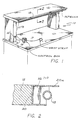
- Fig. 1 the system of the invention is illustrated installed at a work station, typically a work bench 10, having a desk or table top 11 and a shelf 12, both of which typically are connected to ground.
- a control box 13 rests on the work bench and is connected to an electronic package 14 by a cable 15.
- a wrist strap 16 is connected to the control box by a cable 17, and an antenna 18 is connected to the control box by another cable 19.
- the control box can be directly mounted in a pedistal or other component of the work bench.
- the antenna typically is a metal tube supported on electrical insulators, and preferably is disposed in a horizontal configuration along to entire width of the work station above the work surface 11 and spaced outward from the shelf 12. In the embodiment shown in Figs.
- the antenna 18 is an aluminum tube supported within an electrical conducting shield 20 on three spaced insulators 20b which preferably are formed of teflon or polyethylene.
- the shield 20 typically is a U-shaped aluminum extension attached to the forward edge of the shelf 12, with an upper flange 20a projecting beyond the antenna 18 to reduce the likelihood of contact with the antenna by wires and other components resting on the shelf.
- the wrist strap 16 is an electrical conductor which makes direct electrical contact with the operator, and typically is a buckle strap or an elastic expanding strap, such as the type used with wrist watches.
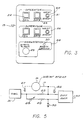
- the control box 13 contains indicator lights, switches, a beeper or other audible signal source, and jacks for plugging in the conductors 17 of the wrist straps.
- a jack 24 provides for receiving the plug of cable 17.
- the lamp units are combination lamp and switch units which are currently available on the market. This permits the operator to actuate switches by pushing on the lamp housing, thereby reducing the frontal space required for the control box. The switches will be described in conjunction with the circuit diagram.
- a similar supervisor section 26 is provided at the control box 13, so that both the operator working at the work station and a supervisor present in the work area can have a wrist strap.
- the operator and supervisor sections 21, 26 are identical.
- a work station section 28 has a static alarm lamp 29 and an earth ground lamp 30. The operation of these lamps will be described in conjunction with the description of the electrical circuitry.
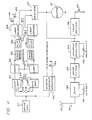
- the static monitoring system of the invention is shown in block diagram form in Fig. 4.
- the antenna 18 is connected via the cable 19 as an input to the amplifier 32.
- the cable 19 preferably is a coaxial polyethylene insulated cable.
- the output of the amplifier 32 is connected through a filter 33 to a window detector 34.
- a variable resistance 35 provides a sensitivity adjustment for the detector and controls the window size.
- the output of the window detector controls the static alarm lamp 29 through a lamp driver 36, and directly controls an audible alarm beeper 37.
- there is a direct connection from the lamp 29 to the power supply because a high intensity lamp is used, which lamp draws considerable current when switched on.
- Another variable resistor 38 provides an offset adjustment for the amplifier 32. For improved stability, a wire wound, multi-turn resistor is preferred for the resistor 38.
- the amplifier 32 functions as a current-to-voltage converter for the signal from the antenna and is configured to be a non-linear operational amplifier so that the system responds to changes in the antenna signal and hence changes in the electrostatic field adjacent the antenna.
- the system does not have to precisely measure the actual magnitude of the electrostatic field adjacent the work station or in the work area. Field strength measurement is relatively difficult, while the measurement of change in field is relatively simple.
- a charged object typically a person
- approaches there is an increase in the electrostatic field at the work station which increase produces a corresponding increase in antenna current.
- This change in antenna current provides the signal which ultimately energizes the lamp 29 and beeper 37.
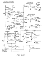
- the presently preferred embodiment of the circuit is shown in greater detail in Fig. 7.
- the operational amplifier 32 has a feedback circuit including resistors 41, 42, 43 connected in series, with the junction of the resistors 41, 42 connected to ground by diodes 44, 45.
- the diodes are connected in parallel with opposite polarity to provide a nonlinear feedback to limit response of the amplifier when strong charges are introduced near the antenna.
- the junction of the feedback resistors 42, 43 is connected to ground through an integrated circuit 47 which functions as an analog switch.
- the integrated circuit 47 controlled by another analog switch 48, functions to make the connection to ground through the resistor 46 in order to set the operational amplifier to the normal state for the ambient field strength. After a short delay, this ground connection is switched to open by the integrated circuit 47 and the operational amplifier functions as described.
- the filter 33 is inserted in order to remove substantially all of the signal resulting from line frequency, which usually is 60 hertz.
- the detector 34 functions as a window detector with a dead zone about the zero signal level and a maximum for limiting the input to the following driver.
- the dead zone is about ⁇ one volt, which prevents the line frequency ripple and the normal drift and noise from producing an alarm.
- the window limits are about ⁇ two volts.
- the sensitivity of the system is controlled by adjusting the variable. resistor 35 in order to set the threshold or minimum signal level which will actuate the alarm.
- the static alarm lamp 29 When there is an increase in electrostatic field adjacent the antenna of a magnitude to produce a signal at the driver in excess of the preset threshold, the static alarm lamp 29 is energized and the beeper 37 is energized. The audible sound from the beeper calls the operator's attention to a problem, and the particular lamp 29 identifies this problem.
- the sensitivity and response on this system is such that an alarm is sounded on approach of a charge well prior to the time that the charge is sufficiently close to the work station to cause damage to the product.
- the wrist strap 16 is connected as one input to a differential amplifier 50, with the other input being provided by an oscillator 51, typically operating at about 500 hertz.
- the oscillatory frequency is selected to be well above that of the line frequency, in order to reduce or eliminate line frequency interference.
- the oscillator frequency should not be so high as to make the capacitances involved very difficult to handle.
- the preferred frequency range is about 200 - 800 hertz.
- the output of the oscillator 51 is also connected to an earth ground unit 52 which functions to energize the earth ground lamp 30 when there is not a proper electrical connection between the circuitry of the system and an earth ground.
- a variable resistor 53 provides for adjusting the output of the differential amplifier 50 to a null for the condition with the wrist strap attached to an operator.
- the amplifier output is connected as input to a comparator 54 having another variable resistor 55 for adjusting the sensitivity of the comparator.
- the comparator output is connected as the input to a lamp driver circuit 56 which provides an output for energizing the lamps 22, 23 of the operator section, and energizing an oscillator 57 which provides a pulsed input to the beeper 37.
- This arrangement permits using a single beeper 37 which produces a continuous tone when energized by the detector 34 and a variable tone when energized by one of the drivers 56.
- An automatic enable unit 60 automatically enables a flip/flop 62 when a wrist strap is picked up from the work bench and attached to an operator.
- a manually actuated switch means 61 is connected to the flip/flop 62 for turning on and off the indicator lamps and beeper.
- the circuitry just described comprises the wrist strap circuit for the operator.
- An identical circuit is shown in Fig. 4 and in Figs. 6 and 7 for the wrist strap circuits for the supervisor.
- the purpose of the wrist strap is to electrically maintain the operator at ground so that there is no potential existing between the operator and the components resting on the work bench and being manipulated by the operator.
- the circuit just described provides an alarm when there is no earth ground in the system and also provides an alarm when the wrist strap ground is not properly attached to the operator and/or not functioning properly.
- the circuit of the invention achieves these aims while being substantially unaffected by electrical noise and provides a fail safe operation so that any malfunction of the system will provide an alarm.
- phase shift balance measuring in the differential amplifier 50 is illustrated in greater detail in the circuit of Fig. 5.
- the output of the oscillator 51 is connected to one input of the differential amplifier 50 through a resistor 65, with the wrist strap 16 also being connected to this input by the cable 17. There is some stray capacitance between the wrist strap cable and ground, and this is indicated at 66. There is also a capacitance to ground resulting from the operator's body, and this is indicated at 67.
- the output of the oscillator 51 is also connected to the second input of the differential amplifier through a variable resistor 68 and another resistor 69, with this input also connected to ground through a capacitor 70.
- the values for the components 68, 69 and 70 are selected to correspond to the values of the components 65, 66 and 67, so that when the wrist strap is properly in place and functioning, there will be a balance of phase at the two inputs to the differential amplifier.
- the variable resistor 68 provides for adjustment of this desired balance. Then any change in the electrical characteristics of the wrist strap circuit will produce a phase shift between the inputs to the differential amplifier, resulting in an output which will energize the alarm circuit, such as by changing an indicator light from safe to fail and/or producing an audible sound.
- the output of the oscillator 51 is connected through a resistor 74 to earth ground at 75.
- this will be a direct electrical connection to a cold water pipe.
- the signal through the resistor 74 is grounded and there is no input to the amplifier 75 of the earth ground unit 52.
- the earth ground connection is open, there will be an input to the amplifier 75 and the earth ground lamp 30 will be energized, providing an indication of a faulty ground.
- the differential amplifier 50 is shown as a single unit in Figs. 4 and 5.
- the operator differential amplifier and the supervisor differential amplifier are provided by five operational amplifiers in a conventional circuit comprising four 324's and one 4558.
- the 4558 output from the differential amplifier is rectified and compared with a reference level in the comparator unit 54.
- a predetermined level as determined by the comparator
- an output is provided to the lamp driver 56.
- the green or safe lamp 23 is energized.
- the output from the comparator on line 77 causes the transistors of the driver 56 to change state, de-energizing the lamp 23 and energizing the red or fail lamp 22.
- the lamp driver is enabled by a transistor switch 78, which switch is controlled by the automatic enable unit shown in detail on Fig. 7.
- the output line 77 from the comparator 54 is also connected as an input to the automatic enable unit 60.
- the signal on line 77 at the input to the unit 60 provides a signal at the output on line 79 which actuates the switch 78 and enables the lamp driver 56.
- neither the fail nor the safe light is energized.
- the safe and fail lamps are now enabled and one or the other is energized depending upon the state of the system. Thus the operator does not have to perform any function to bring the system into operation.
- the analog switch 48a which is controlled by the switch 48 to close the switch 48a at power on for a short time, always places the flip-flop 62 in the disabled state.
- the switch unit 61 comprises a first switch mounted with the green or safe indicator 23 and a second switch mounted with the red or fail indicator 22.
- Each switch has a set of normally closed contacts and a set of normally open contacts, as indicated at 61 in Fig. 6.
- the beeper for the wrist strap section When the beeper for the wrist strap section is energized, it continues to operate until shut-off. This is accomplished by depressing the switches of both the red and green lights, which opens the circuit between the terminals BEEP1 and BEEP2, which in turn actuates the flip/flop 62 and shuts down the oscillator 57. Also, actuation of either of the red or green switches will close a circuit between terminals OP-EN1 and OP-EN2 and change the output from the autoenable unit and thereby de-energize both indicator lamps.
- the wrist strap monitor senses the effect of both the operator and the supervisor on the wrist strap lines. In addition, it monitors the difference between earth ground and electrical ground to ensure the connections to ground.
- the device detects a person picking up the wrist strap and automatically enables, indicated by a safe condition (green lamp). If for any reason the wrist strap should fail or the person lose connection to the wrist strap monitor, a red lamp is illuminated and an audible alarm is activated until a safe condition is restored or the unit is disabled. The unit is enabled/disabled by pressing either of the fail or safe buttons.
- a safe condition green lamp
- the static monitor utilizes a static antenna to map the bench work surface for potentially hazardous charges.
- the antenna attempts to neutralize any charges in the vicinity of the work area and constantly looks for static disturbances in the work area. Charges entering the area instantly set off the constant tone static alarm long before they present any threat to static sensitive components in the work area. A sensitivity adjustment is provided to control static level at which the alarm sounds.
- the static unit once installed, operating at normal sensitivities, will easily detect and alarm when individuals approach the bench wearing wool clothing, rubber soled shoes (tennis shoes on carpeting), silk tops, etc.
- Chairs with hard rubber casters cannot be rolled on conventional carpeting near the bench, nor can CRT monitors and other static producing instruments be allowed in the vicinity of a static controlled work station without detection by the static monitoring system.
Landscapes
- Physics & Mathematics (AREA)
- General Physics & Mathematics (AREA)
- Elimination Of Static Electricity (AREA)
- Emergency Alarm Devices (AREA)
Applications Claiming Priority (2)
| Application Number | Priority Date | Filing Date | Title |
|---|---|---|---|
| US06/877,873 US4785294A (en) | 1986-06-24 | 1986-06-24 | Static monitoring system |
| US877873 | 1986-06-24 |
Publications (2)
| Publication Number | Publication Date |
|---|---|
| EP0251532A2 true EP0251532A2 (de) | 1988-01-07 |
| EP0251532A3 EP0251532A3 (de) | 1989-10-25 |
Family
ID=25370893
Family Applications (1)
| Application Number | Title | Priority Date | Filing Date |
|---|---|---|---|
| EP87305190A Ceased EP0251532A3 (de) | 1986-06-24 | 1987-06-12 | Überwachung statischer Ladung |
Country Status (3)
| Country | Link |
|---|---|
| US (1) | US4785294A (de) |
| EP (1) | EP0251532A3 (de) |
| JP (1) | JPS6313299A (de) |
Cited By (3)
| Publication number | Priority date | Publication date | Assignee | Title |
|---|---|---|---|---|
| DE3908590A1 (de) * | 1989-03-16 | 1990-09-20 | Hella Kg Hueck & Co | Einrichtung zur messung, ueberwachung und auswertung elektrostatischer parameter bei der auf- und/oder entladung von koerpern |
| EP0649027A3 (de) * | 1993-10-12 | 1996-05-01 | Harris Corp | Auf einer Widerstandsmessung basierende Einrichtung, die die Unversehrtheit der Erdverbindung einer elektronischen Komponente handhabenden Vorrichtung überwacht. |
| DE19636277A1 (de) * | 1996-09-06 | 1998-03-12 | Globalmind Consumer Electronic | Vorrichtung zur Detektion elektromagnetischer Wechselfelder |
Families Citing this family (23)
| Publication number | Priority date | Publication date | Assignee | Title |
|---|---|---|---|---|
| US5051732A (en) * | 1988-08-29 | 1991-09-24 | Ericson Manufacturing Company | Power outlet ground integrity and wriststrap monitor circuit |
| US5057965A (en) * | 1989-07-06 | 1991-10-15 | Minnesota Mining And Manufacturing Company | Work station monitor |
| US5225808A (en) * | 1990-08-08 | 1993-07-06 | Olivadotti William C | Long range intruder sensor |
| US5359319A (en) * | 1990-08-13 | 1994-10-25 | Minnesota Mining And Manufacturing Company | Electrostatic discharge detector and display |
| CA2076488A1 (en) * | 1991-09-27 | 1993-03-28 | James A. Quinn | Continuous monitoring electrostatic discharge system |
| DE4134695A1 (de) * | 1991-10-21 | 1993-04-22 | Beha C Gmbh | Pruefgeraet zur anzeige elektrischer spannung |
| EP0580913A1 (de) * | 1992-07-30 | 1994-02-02 | International Business Machines Corporation | System zur Fehleranzeige eines persönlichen elektrostatischen Entladungsschutzgerätes |
| US5408186A (en) * | 1993-10-05 | 1995-04-18 | Bakhoum; Ezzat G. | Single-conductor wrist strap monitoring |
| US5666106A (en) * | 1996-09-04 | 1997-09-09 | Micron Electronics, Inc. | Accessway with grounding sensor |
| US5986629A (en) * | 1996-10-02 | 1999-11-16 | Xerox Corporation | Electrostatic discharge indicator |
| US5952931A (en) * | 1997-01-07 | 1999-09-14 | Seagate Technology, Inc. | Checker box of wrist-strap monitoring |
| US6078875A (en) * | 1997-08-20 | 2000-06-20 | Semtronics Corporation | Automated auditing system |
| US6052053A (en) | 1997-10-22 | 2000-04-18 | Semtronics Corporation | Continuous monitoring system |
| US6930612B1 (en) * | 2002-10-04 | 2005-08-16 | Credence Technologies, Inc. | Device and method of monitoring grounding of personnel and equipment in ESD-sensitive areas |
| US7049972B2 (en) * | 2003-08-29 | 2006-05-23 | Fabian Carl E | Lightning strike hazard detector |
| US8073548B2 (en) * | 2004-08-24 | 2011-12-06 | Sensors For Medicine And Science, Inc. | Wristband or other type of band having an adjustable antenna for use with a sensor reader |
| CN100573163C (zh) * | 2006-08-11 | 2009-12-23 | 鸿富锦精密工业(深圳)有限公司 | 静电警示模块 |
| CN100573375C (zh) * | 2006-09-26 | 2009-12-23 | 深圳长城开发科技股份有限公司 | 静电实时监控系统及其数据采集和分析方法 |
| US20100051502A1 (en) * | 2008-09-04 | 2010-03-04 | 3M Innovative Properties Company | Carrier having integral detection and measurement of environmental parameters |
| US8963552B2 (en) | 2012-04-26 | 2015-02-24 | 3M Innovative Properties Company | Electrostatic discharge event detector |
| CN103884951B (zh) * | 2012-12-21 | 2016-08-10 | 纬创资通股份有限公司 | 静电防护装置监控电路及静电防护装置监控系统 |
| JP2015049090A (ja) * | 2013-08-30 | 2015-03-16 | Necフィールディング株式会社 | 静電気対策ツールの接地状態確認装置および確認方法 |
| CN213595976U (zh) * | 2020-09-23 | 2021-07-02 | 哈斯孔宁Dhv荷兰有限公司 | 废水布水系统和具有该废水布水系统的反应器 |
Family Cites Families (10)
| Publication number | Priority date | Publication date | Assignee | Title |
|---|---|---|---|---|
| US330A (en) * | 1837-07-31 | Machine foe cleaning and dressing | ||
| US3973208A (en) * | 1975-02-14 | 1976-08-03 | Dovey Manufacturing Company | Capacitor detector device |
| DE2550713A1 (de) * | 1975-11-12 | 1977-05-18 | Bodo Schumann | Vorrichtung zum erfassen eines elektrischen bzw. elektrostatischen feldes bzw. einer aenderung desselben |
| US4366473A (en) * | 1980-01-15 | 1982-12-28 | Matsushita Electric Works, Ltd. | Capacitively coupled electromagnetic intrusion warning system |
| US4558309A (en) * | 1983-06-27 | 1985-12-10 | The Simco Company, Inc. | Ground tether continuity monitor |
| US4649374A (en) * | 1984-01-06 | 1987-03-10 | Spectrascan, Inc. | Electrostatic system monitor and method therefor |
| USH330H (en) | 1984-07-02 | 1987-09-01 | The United States Of America As Represented By The Secretary Of The Navy | Personnel grounding system tester |
| US4684931A (en) * | 1985-05-14 | 1987-08-04 | Sydney Parks | Capacitive sensing security system |
| US4638399A (en) * | 1985-10-04 | 1987-01-20 | Plug-In Storage Systems, Inc. | Wrist strap ground monitor |
| US4710751A (en) * | 1986-04-24 | 1987-12-01 | Environmental Protection Systems | Ground fault monitor circuit |
-
1986
- 1986-06-24 US US06/877,873 patent/US4785294A/en not_active Expired - Fee Related
-
1987
- 1987-06-12 EP EP87305190A patent/EP0251532A3/de not_active Ceased
- 1987-06-23 JP JP62154590A patent/JPS6313299A/ja active Pending
Cited By (4)
| Publication number | Priority date | Publication date | Assignee | Title |
|---|---|---|---|---|
| DE3908590A1 (de) * | 1989-03-16 | 1990-09-20 | Hella Kg Hueck & Co | Einrichtung zur messung, ueberwachung und auswertung elektrostatischer parameter bei der auf- und/oder entladung von koerpern |
| EP0649027A3 (de) * | 1993-10-12 | 1996-05-01 | Harris Corp | Auf einer Widerstandsmessung basierende Einrichtung, die die Unversehrtheit der Erdverbindung einer elektronischen Komponente handhabenden Vorrichtung überwacht. |
| DE19636277A1 (de) * | 1996-09-06 | 1998-03-12 | Globalmind Consumer Electronic | Vorrichtung zur Detektion elektromagnetischer Wechselfelder |
| DE19636277C2 (de) * | 1996-09-06 | 2001-07-05 | Globalmind Consumer Electronic | Vorrichtung zur Detektion elektromagnetischer Wechselfelder |
Also Published As
| Publication number | Publication date |
|---|---|
| JPS6313299A (ja) | 1988-01-20 |
| US4785294A (en) | 1988-11-15 |
| EP0251532A3 (de) | 1989-10-25 |
Similar Documents
| Publication | Publication Date | Title |
|---|---|---|
| US4785294A (en) | Static monitoring system | |
| US3896425A (en) | Proximity detector | |
| US5952820A (en) | Foreign voltage detector | |
| EP0681706B1 (de) | Vorrichtung zum aufspueren von unterirdischen leitern | |
| US5291208A (en) | Incipient lightning detection and device protection | |
| US3986110A (en) | Water depth measuring device | |
| US6163144A (en) | Electrical circuit tracing apparatus using modulated tracing signal | |
| US4710751A (en) | Ground fault monitor circuit | |
| EP0407186B1 (de) | Arbeitsplatzmonitor | |
| US20050264427A1 (en) | Electrical injury protection system | |
| US4906938A (en) | Power circuit locater | |
| CA1145400A (en) | Ground-isolated electrostatic field detector | |
| US4724382A (en) | Testing instrument for detectlng alternating voltages in mains and alternating electromagnetic fields in the vicinity of voltage-carrying conductors | |
| US6897783B2 (en) | Electrical injury protection system using radio frequency transmission | |
| US5969516A (en) | Electrical circuit interrupter device locator | |
| US3737765A (en) | Isolated power ground fault detector system | |
| US6853307B2 (en) | High voltage proximity warning system and method | |
| US5001465A (en) | Crane boom electrostatic . . . alarm | |
| US4755805A (en) | Current sensing alarm arrangement for monitoring the presence of high voltage | |
| US20040080320A1 (en) | Electric shock alert watch | |
| US3699432A (en) | Electrical shock hazard detection system with station scanning and indicating means | |
| US3573783A (en) | Proximity sensor | |
| CA1161517A (en) | Intrusion warning system | |
| US4823115A (en) | Detection of lightning, storms and the like | |
| CA2086640C (en) | Electrical contact avoidance device |
Legal Events
| Date | Code | Title | Description |
|---|---|---|---|
| PUAI | Public reference made under article 153(3) epc to a published international application that has entered the european phase |
Free format text: ORIGINAL CODE: 0009012 |
|
| AK | Designated contracting states |
Kind code of ref document: A2 Designated state(s): AT BE CH DE ES FR GB GR IT LI LU NL SE |
|
| PUAL | Search report despatched |
Free format text: ORIGINAL CODE: 0009013 |
|
| AK | Designated contracting states |
Kind code of ref document: A3 Designated state(s): AT BE CH DE ES FR GB GR IT LI LU NL SE |
|
| 17P | Request for examination filed |
Effective date: 19891218 |
|
| 17Q | First examination report despatched |
Effective date: 19910819 |
|
| STAA | Information on the status of an ep patent application or granted ep patent |
Free format text: STATUS: THE APPLICATION HAS BEEN REFUSED |
|
| 18R | Application refused |
Effective date: 19920210 |
|
| RIN1 | Information on inventor provided before grant (corrected) |
Inventor name: CAMPBELL, JEFFREY D |