EP0251572A2 - Dispositif de verrouillage pour sangle - Google Patents
Dispositif de verrouillage pour sangle Download PDFInfo
- Publication number
- EP0251572A2 EP0251572A2 EP87305382A EP87305382A EP0251572A2 EP 0251572 A2 EP0251572 A2 EP 0251572A2 EP 87305382 A EP87305382 A EP 87305382A EP 87305382 A EP87305382 A EP 87305382A EP 0251572 A2 EP0251572 A2 EP 0251572A2
- Authority
- EP
- European Patent Office
- Prior art keywords
- base plate
- strap fastener
- locking
- belt
- cover plate
- Prior art date
- Legal status (The legal status is an assumption and is not a legal conclusion. Google has not performed a legal analysis and makes no representation as to the accuracy of the status listed.)
- Granted
Links
Images


Classifications
-
- A—HUMAN NECESSITIES
- A45—HAND OR TRAVELLING ARTICLES
- A45C—PURSES; LUGGAGE; HAND CARRIED BAGS
- A45C13/00—Details; Accessories
-
- A—HUMAN NECESSITIES
- A44—HABERDASHERY; JEWELLERY
- A44B—BUTTONS, PINS, BUCKLES, SLIDE FASTENERS, OR THE LIKE
- A44B11/00—Buckles; Similar fasteners for interconnecting straps or the like, e.g. for safety belts
- A44B11/20—Buckles; Similar fasteners for interconnecting straps or the like, e.g. for safety belts engaging holes or the like in strap
- A44B11/22—Buckle with fixed prong
- A44B11/226—Buckle with fixed prong with cover plate
-
- A—HUMAN NECESSITIES
- A45—HAND OR TRAVELLING ARTICLES
- A45C—PURSES; LUGGAGE; HAND CARRIED BAGS
- A45C13/00—Details; Accessories
- A45C13/30—Straps; Bands
-
- Y—GENERAL TAGGING OF NEW TECHNOLOGICAL DEVELOPMENTS; GENERAL TAGGING OF CROSS-SECTIONAL TECHNOLOGIES SPANNING OVER SEVERAL SECTIONS OF THE IPC; TECHNICAL SUBJECTS COVERED BY FORMER USPC CROSS-REFERENCE ART COLLECTIONS [XRACs] AND DIGESTS
- Y10—TECHNICAL SUBJECTS COVERED BY FORMER USPC
- Y10T—TECHNICAL SUBJECTS COVERED BY FORMER US CLASSIFICATION
- Y10T24/00—Buckles, buttons, clasps, etc.
- Y10T24/34—Combined diverse multipart fasteners
- Y10T24/3401—Buckle
- Y10T24/3403—Buckle and buckles
- Y10T24/3405—Buckle and buckles having separate disconnect means
- Y10T24/3407—Pivotal lever type
-
- Y—GENERAL TAGGING OF NEW TECHNOLOGICAL DEVELOPMENTS; GENERAL TAGGING OF CROSS-SECTIONAL TECHNOLOGIES SPANNING OVER SEVERAL SECTIONS OF THE IPC; TECHNICAL SUBJECTS COVERED BY FORMER USPC CROSS-REFERENCE ART COLLECTIONS [XRACs] AND DIGESTS
- Y10—TECHNICAL SUBJECTS COVERED BY FORMER USPC
- Y10T—TECHNICAL SUBJECTS COVERED BY FORMER US CLASSIFICATION
- Y10T24/00—Buckles, buttons, clasps, etc.
- Y10T24/40—Buckles
- Y10T24/4072—Pivoted lever
- Y10T24/4077—Looped strap
-
- Y—GENERAL TAGGING OF NEW TECHNOLOGICAL DEVELOPMENTS; GENERAL TAGGING OF CROSS-SECTIONAL TECHNOLOGIES SPANNING OVER SEVERAL SECTIONS OF THE IPC; TECHNICAL SUBJECTS COVERED BY FORMER USPC CROSS-REFERENCE ART COLLECTIONS [XRACs] AND DIGESTS
- Y10—TECHNICAL SUBJECTS COVERED BY FORMER USPC
- Y10T—TECHNICAL SUBJECTS COVERED BY FORMER US CLASSIFICATION
- Y10T24/00—Buckles, buttons, clasps, etc.
- Y10T24/44—Clasp, clip, support-clamp, or required component thereof
- Y10T24/44641—Clasp, clip, support-clamp, or required component thereof having gripping member formed from, biased by, or mounted on resilient member
- Y10T24/44744—Clasp, clip, support-clamp, or required component thereof having gripping member formed from, biased by, or mounted on resilient member with position locking-means for engaging faces
- Y10T24/44752—Integral locking-means
Definitions
- the present invention relates to a strap fastener for use on shoulder bags, rucksacks, school knapsacks or other bags for connecting the end of a belt or strap to the body of a bag.
- the present invention seeks to provide a strap fastener for releasably connecting the end of a belt or strap to the body of a bag in firmly gripped condition.
- the present invention further seeks to provide a strap fastener having structural features which enable easy adjustment of the effective length of a belt or strap on a bag.
- a strap fastener for connecting a belt to the body of a bag, comprising: a base plate adapted to be mounted on the body of the bag, said base plate including a locking nose at one of its opposite ends, and a presser projection intermediately between said opposite ends; and a cover plate pivotably connected at one of its opposite ends to the other end of said base plate, said cover plate having at the other end thereof a locking projection lockingly engageable with said locking nose to interlock said cover plate and said base plate, and at least slot for the passage therethrough of the belt and receptive of said presser projection, when said cover plate is locked on said base plate said presser projection being received in said slot and urging the belt against a portion of said cover plate defining said slot to grip the belt therebetween.
- a strap fastener 10 embodying the present invention generally comprises a base plate 11 adapted to be mounted on the body C of a bag, and a cover plate 12 pivotably connected to a lower end of the base plate 11.
- the base plate 11 and the cover plate 12 are injection-molded of synthetic resin in assembled condition.
- the base plate 11 is of a generally rectangular shape and includes a hook-shaped locking projection or nose 13 extending along an upper edge of the base plate 11 and facing downwardly in Figure 1, and a pair of coaxial shafts 14 projecting laterally outwardly from the lower end of the base plate 11.
- the locking nose 13 is recessed as at 13a to define therein a retaining recess opening downwardly for releasably receiving therein a portion of the cover plate 12.
- the base plate 11 further includes a presser projection 15 disposed centrally between the locking nose 13 and the shafts 14 and extending parallel to the shafts 14.
- the presser projection 15 cooperates with a portion of the cover plate 12 in firmly holding a belt B therebetween against displacement, as described later on.
- the presser projection 15 has a locking protuberance 15a swelled or protruding toward the locking nose 13.
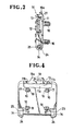
- the base plate 11 also includes four attachment posts or columns 16 projecting perpendicularly from the underside of the base plate 11 for attaching the strap fastener 10 to the body C of a bag.
- the attachment posts 16 have a substantially square cross-sectional shape ( Figure 4) and are located near four corners of the rectangular base plate 11, respectively.
- Each of the attachment posts 16 has a series of saw-teeth or serrations 17 on two adjacent side walls thereof and a guide ridge 18 on one of the remaining side walls. Though not designated, each saw tooth 17 includes a vertical surface facing toward the base plate 11 and a sloping surface facing away from the base plate ll.
- the attachment posts 16 are driven through corresponding openings formed in the bag body C and then are held on a retainer plate 30, thereby mounting the strap fastener 10 on the bag.
- the attachment posts 16 may be fused to the retainer plate 30.
- the base plate 11 further has an elongate opening lla extending along the locking nose 13, and a pair of grooves llb, llb disposed on opposite sides of the locking nose 13 and opening at one end to the elongate opening lla.
- the upper end portion of the base plate 11 posesses a certain degree of resiliency so that the locking nose 13 is tiltable about its distal end upwardly away from the presser projection 15.
- a suitable tool such as a screwdriver D is angularly moved or tilted in the direction indicated by the arrow A in Figure 7 while a tip of the screwdriver D is received in a groove 19 defined in a flap 19a which projects upwardly outwardly from the locking nose 13, away from the presser projection 15.
- the grooves llb may be omitted in which instance the locking nose 13 is tiltable about the upper edge of the base plate 11 and hence the screw driver D is tilted in a direction opposite to the direction of the arrow A.
- the cover plate 12 is of a generally rectangular shape and has three parallel spaced transverse slots 20, 21, 22 for the passage therethrough of the belt B.
- the intermediate slot 21 has a width large enough to concurrently receive the presser projection 15 and the portion of the belt B.
- the lower end of the cover plate 12 is centrally recessed as at 23 so as to leaving a pair of parallel spaced support flanges 24, 24 on opposite sides of the recess 23.
- the support flanges 24, 24 have a pair of coaxial holes 25, 25, respectively, in which the shafts 14 of the base plate 11 are rotatably received.
- the shafts 14 and the support flanges 24 constitute a hinge joint by means of which the cover plate 12 is pivotably movable with respect to the base plate 11.
- the intermediate slot 21 and the upper slot 22 are separated by a cross bar 26.
- the cross bar 26 has a longitudinal locking ridge 26a extending along its rear edge and projecting into the intermediate slot 21.
- the retainer plate 30 is molded of synthetic resin and has four openings or holes 31 for receiving therein the corresponding attachment posts 16 on the base plate 11, each of the openings 31 having four adjoining axial grooves.
- the retainer palte 30 further includes three locking pawls 32 projecting into each of the holes 31 and lockingly engageable with the saw-teeth 17 on one attachment post 16 to couple the base plate 11 with the retainer plate 30.
- the locking pawls 32 are disposed adjacent to one end of the hole 31 and inclined toward the other end.
- One of the axial grooves is flat throughout the length thereof and is free of the locking pawl 32. This axial groove 32 serves as a guideway for guidingly receiving therein the guide ridge 18 on each attachment post 16.
- the attachment posts 16 are driven through the fabric of the bag body C ( Figure 1) and then through the holes 31 in the retainer plate 30 ( Figure 7).
- the guide ridges 18 on the attachment posts 16 are guidedly received in the guide grooves 33 in the respective holes 31. Insertion of the attachment posts 16 into the holes 31 is effected stepwise but smoothly because the saw-teeth 17 on the attachment posts 16 slope in the direction of movement of the attachment posts 16 which is the same of the direction of inclination of the locking pawls 32.
- one end of a belt B is looped on the cover plate in such a manner that the belt end passes successively through the transverse slots 20 - 21 in a meandering or zig-zag formation while looping aound the interior side of the cross bar 26, as shown in Figure 1.
- the cover plate 12 is turned about the shafts 14 toward the base plate 11. This angular movement of the cover plate 12 causes the locking projection 27 to engage and then slide down the locking nose 13.
- the upper end portion of the base plate 11 is resiliently deformed to allow the locking nose 13 to tilt outwardly.
- a further angular movement of the cover plate 12 causes the locking projection 27 to move past the locking nose 13 whereupon the locking projection 27 is snapped into the retaining recess 13a where the locking projection 27 is held in interlocking engagement with the locking nose 13.
- the locking protuberance 15a is snapped over the belt portion extending around the locking ridge 26a.
- the cover plate 12 is locked on the base plate, as shown in Figure 7.
- the presser projection 15 is received in the transverse slot 21 and presses the belt end against the cross bar 26.
- the locking protuberance 15a and the locking ridge 26a bite into the belt B, thereby retaining the belt end against removal.
- the belt end is looped around the interior side of the cross bar 26, it is possible to adjust the effective length of the belt B when the cover plate 12 is kept in unlocked condition. If the belt-length adjustment is not necessary, the upper and lower transverse slots 20, 22 may be omitted, in which instance, the balt B is frictionally gripped by and between the presser projection 15 and a side wall of the cover plate 12 defining a single transverse slot through which the belt end is inserted in the strap fastener.
Landscapes
- Purses, Travelling Bags, Baskets, Or Suitcases (AREA)
- Buckles (AREA)
- Clamps And Clips (AREA)
Applications Claiming Priority (2)
| Application Number | Priority Date | Filing Date | Title |
|---|---|---|---|
| JP9813486 | 1986-06-26 | ||
| JP98134/86U | 1986-06-26 |
Publications (3)
| Publication Number | Publication Date |
|---|---|
| EP0251572A2 true EP0251572A2 (fr) | 1988-01-07 |
| EP0251572A3 EP0251572A3 (en) | 1988-09-28 |
| EP0251572B1 EP0251572B1 (fr) | 1991-11-21 |
Family
ID=14211772
Family Applications (1)
| Application Number | Title | Priority Date | Filing Date |
|---|---|---|---|
| EP87305382A Expired - Lifetime EP0251572B1 (fr) | 1986-06-26 | 1987-06-17 | Dispositif de verrouillage pour sangle |
Country Status (10)
| Country | Link |
|---|---|
| US (1) | US4815175A (fr) |
| EP (1) | EP0251572B1 (fr) |
| JP (1) | JPH0546652Y2 (fr) |
| KR (1) | KR900001636Y1 (fr) |
| AU (1) | AU574612B2 (fr) |
| CA (1) | CA1295111C (fr) |
| DE (1) | DE3774625D1 (fr) |
| HK (1) | HK97594A (fr) |
| MY (1) | MY100855A (fr) |
| SG (1) | SG102194G (fr) |
Cited By (1)
| Publication number | Priority date | Publication date | Assignee | Title |
|---|---|---|---|---|
| FR2842080A1 (fr) * | 2002-07-12 | 2004-01-16 | Exel Ind | "dispositif de liaison rapide d'une sangle a un objet portable" |
Families Citing this family (12)
| Publication number | Priority date | Publication date | Assignee | Title |
|---|---|---|---|---|
| JPH0636728Y2 (ja) * | 1988-06-17 | 1994-09-28 | 吉田工業株式会社 | 係止具 |
| IT1225582B (it) * | 1988-07-21 | 1990-11-22 | Brancalesport Di Elena Brancal | Casco di protezione. |
| US5308337A (en) * | 1993-03-16 | 1994-05-03 | Bingisser Timothy A | Medical tube clip device |
| JP3449899B2 (ja) * | 1997-10-16 | 2003-09-22 | 北川工業株式会社 | 基台固定構造 |
| EP1177740A1 (fr) | 2000-07-31 | 2002-02-06 | Acqua di Parma S.r.l. | Fermeture pour courroie d'épaule d'un sac à main |
| US6510592B1 (en) | 2000-10-11 | 2003-01-28 | Illinois Tool Works Inc. | Clip for attaching pouches and similar devices |
| SE525116C2 (sv) * | 2002-04-05 | 2004-11-30 | Nina Story | Informationsband |
| US7377390B2 (en) * | 2003-05-27 | 2008-05-27 | Mattel, Inc. | Stand for doll attachment |
| JP2007020948A (ja) * | 2005-07-19 | 2007-02-01 | Ykk Corp | 係止具 |
| JP4909714B2 (ja) * | 2006-11-17 | 2012-04-04 | Ykk株式会社 | シート装着器具 |
| GB0922614D0 (en) * | 2009-12-23 | 2010-02-10 | Butterfield Forbes | Device |
| US20180344014A1 (en) * | 2017-06-06 | 2018-12-06 | Under Armour, Inc. | Article with Reconfigurable Straps |
Family Cites Families (14)
| Publication number | Priority date | Publication date | Assignee | Title |
|---|---|---|---|---|
| US1311120A (en) * | 1919-07-22 | Planograph co | ||
| US804397A (en) * | 1904-12-08 | 1905-11-14 | Edwin A Grushus | Cinch-grip. |
| FR1358218A (fr) * | 1963-05-31 | 1964-04-10 | Ceinture de sécurité, notamment pour véhicules automobiles | |
| GB1269858A (en) * | 1969-12-16 | 1972-04-06 | Carr Fastener Co Ltd | Strap buckle |
| US3886632A (en) * | 1974-01-30 | 1975-06-03 | Kidde Co Presto Lock Div | Buckle |
| DE2524269A1 (de) * | 1975-05-31 | 1976-12-09 | Kunststoff Gmbh | Halter fuer stangen, rohre, kabel o.dgl. |
| US4220301A (en) * | 1979-05-07 | 1980-09-02 | Safe-T-Gard, Inc. | Flexible strap type mounting device |
| JPS6483Y2 (fr) * | 1981-03-13 | 1989-01-05 | ||
| FR2522255A1 (fr) * | 1982-02-26 | 1983-09-02 | Itw De France | Dispositif de bouclerie |
| US4484397A (en) * | 1983-06-21 | 1984-11-27 | Curley Jr John J | Stabilization device |
| SE441261B (sv) * | 1984-03-26 | 1985-09-23 | Jan Ingemar Neslund | Pasklemma |
| US4567628A (en) * | 1984-10-05 | 1986-02-04 | Ancra Corporation | Cam buckle assembly for use in tying down loads |
| JPH0130883Y2 (fr) * | 1984-12-11 | 1989-09-21 | ||
| JPS61111304U (fr) * | 1984-12-26 | 1986-07-14 |
-
1987
- 1987-06-08 MY MYPI87000779A patent/MY100855A/en unknown
- 1987-06-15 AU AU74253/87A patent/AU574612B2/en not_active Ceased
- 1987-06-16 CA CA000539745A patent/CA1295111C/fr not_active Expired - Lifetime
- 1987-06-17 EP EP87305382A patent/EP0251572B1/fr not_active Expired - Lifetime
- 1987-06-17 JP JP1987093181U patent/JPH0546652Y2/ja not_active Expired - Lifetime
- 1987-06-17 DE DE8787305382T patent/DE3774625D1/de not_active Expired - Lifetime
- 1987-06-25 KR KR2019870010203U patent/KR900001636Y1/ko not_active Expired
- 1987-06-26 US US07/067,738 patent/US4815175A/en not_active Expired - Fee Related
-
1994
- 1994-07-26 SG SG102194A patent/SG102194G/en unknown
- 1994-09-15 HK HK97594A patent/HK97594A/en unknown
Cited By (1)
| Publication number | Priority date | Publication date | Assignee | Title |
|---|---|---|---|---|
| FR2842080A1 (fr) * | 2002-07-12 | 2004-01-16 | Exel Ind | "dispositif de liaison rapide d'une sangle a un objet portable" |
Also Published As
| Publication number | Publication date |
|---|---|
| HK97594A (en) | 1994-09-23 |
| CA1295111C (fr) | 1992-02-04 |
| JPS6375229U (fr) | 1988-05-19 |
| DE3774625D1 (de) | 1992-01-02 |
| SG102194G (en) | 1994-10-28 |
| KR900001636Y1 (ko) | 1990-03-03 |
| AU7425387A (en) | 1988-01-07 |
| MY100855A (en) | 1991-03-15 |
| EP0251572B1 (fr) | 1991-11-21 |
| JPH0546652Y2 (fr) | 1993-12-07 |
| KR880000188U (ko) | 1988-02-17 |
| EP0251572A3 (en) | 1988-09-28 |
| US4815175A (en) | 1989-03-28 |
| AU574612B2 (en) | 1988-07-07 |
Similar Documents
| Publication | Publication Date | Title |
|---|---|---|
| US4815175A (en) | Strap fastener | |
| US4800629A (en) | Plastic buckle | |
| CA2003937C (fr) | Mecanisme de scellement de securite | |
| EP0464753B1 (fr) | Crochet pour fermeture du type à éléments d'accrochage moulé d'une seule pièce | |
| US4712280A (en) | Strap fastener | |
| US4406043A (en) | Belt buckle construction | |
| US7526842B2 (en) | Quick-mount flexible interlocking attaching system | |
| WO1987003790A1 (fr) | Attache du type a boucle | |
| US5566427A (en) | Strap clip and retainer | |
| US4864700A (en) | Buckle assembly | |
| EP0260959A2 (fr) | Fixation de courroie | |
| CN111938279A (zh) | 搭扣 | |
| US4949436A (en) | Press release fastener | |
| US5014399A (en) | Sheet fastening assembly and fastener therefor | |
| GB2125880A (en) | Sliding bar buckle | |
| US20020062543A1 (en) | Aid for threading a seat belt through a child safety restraint | |
| EP0169342A2 (fr) | Boucle | |
| US6163941A (en) | Adjustable buckle device | |
| GB2180591A (en) | End terminating means for zip fasteners | |
| US7204002B2 (en) | Buckle and baby carrier using the same | |
| EP0704177A1 (fr) | Butée d'arrêt inférieure séparable en résine synthétique pour fermeture à glissière | |
| EP0311042B1 (fr) | Boucle | |
| US5533240A (en) | Lock fastener | |
| US5339501A (en) | Snap and ratchet panel fastener and support assembly | |
| CA1311910C (fr) | Dispositif a crochets, en resine synthetique |
Legal Events
| Date | Code | Title | Description |
|---|---|---|---|
| PUAI | Public reference made under article 153(3) epc to a published international application that has entered the european phase |
Free format text: ORIGINAL CODE: 0009012 |
|
| AK | Designated contracting states |
Kind code of ref document: A2 Designated state(s): DE FR GB IT |
|
| PUAL | Search report despatched |
Free format text: ORIGINAL CODE: 0009013 |
|
| AK | Designated contracting states |
Kind code of ref document: A3 Designated state(s): DE FR GB IT |
|
| 17P | Request for examination filed |
Effective date: 19881229 |
|
| 17Q | First examination report despatched |
Effective date: 19900327 |
|
| GRAA | (expected) grant |
Free format text: ORIGINAL CODE: 0009210 |
|
| AK | Designated contracting states |
Kind code of ref document: B1 Designated state(s): DE FR GB IT |
|
| ITF | It: translation for a ep patent filed | ||
| ET | Fr: translation filed | ||
| REF | Corresponds to: |
Ref document number: 3774625 Country of ref document: DE Date of ref document: 19920102 |
|
| PLBE | No opposition filed within time limit |
Free format text: ORIGINAL CODE: 0009261 |
|
| STAA | Information on the status of an ep patent application or granted ep patent |
Free format text: STATUS: NO OPPOSITION FILED WITHIN TIME LIMIT |
|
| 26N | No opposition filed | ||
| ITPR | It: changes in ownership of a european patent |
Owner name: CAMBIO RAGIONE SOCIALE;YKK CORPORATION |
|
| REG | Reference to a national code |
Ref country code: FR Ref legal event code: CD |
|
| PGFP | Annual fee paid to national office [announced via postgrant information from national office to epo] |
Ref country code: FR Payment date: 19950519 Year of fee payment: 9 |
|
| PGFP | Annual fee paid to national office [announced via postgrant information from national office to epo] |
Ref country code: GB Payment date: 19950606 Year of fee payment: 9 |
|
| PGFP | Annual fee paid to national office [announced via postgrant information from national office to epo] |
Ref country code: DE Payment date: 19950731 Year of fee payment: 9 |
|
| PG25 | Lapsed in a contracting state [announced via postgrant information from national office to epo] |
Ref country code: GB Effective date: 19960617 |
|
| GBPC | Gb: european patent ceased through non-payment of renewal fee |
Effective date: 19960617 |
|
| PG25 | Lapsed in a contracting state [announced via postgrant information from national office to epo] |
Ref country code: FR Effective date: 19970228 |
|
| PG25 | Lapsed in a contracting state [announced via postgrant information from national office to epo] |
Ref country code: DE Effective date: 19970301 |
|
| REG | Reference to a national code |
Ref country code: FR Ref legal event code: ST |
|
| PG25 | Lapsed in a contracting state [announced via postgrant information from national office to epo] |
Ref country code: IT Free format text: LAPSE BECAUSE OF NON-PAYMENT OF DUE FEES;WARNING: LAPSES OF ITALIAN PATENTS WITH EFFECTIVE DATE BEFORE 2007 MAY HAVE OCCURRED AT ANY TIME BEFORE 2007. THE CORRECT EFFECTIVE DATE MAY BE DIFFERENT FROM THE ONE RECORDED. Effective date: 20050617 |