EP0251576A2 - Datenerwerbungssystem - Google Patents
Datenerwerbungssystem Download PDFInfo
- Publication number
- EP0251576A2 EP0251576A2 EP87305392A EP87305392A EP0251576A2 EP 0251576 A2 EP0251576 A2 EP 0251576A2 EP 87305392 A EP87305392 A EP 87305392A EP 87305392 A EP87305392 A EP 87305392A EP 0251576 A2 EP0251576 A2 EP 0251576A2
- Authority
- EP
- European Patent Office
- Prior art keywords
- nodal
- unit
- sensors
- sensor
- central unit
- Prior art date
- Legal status (The legal status is an assumption and is not a legal conclusion. Google has not performed a legal analysis and makes no representation as to the accuracy of the status listed.)
- Withdrawn
Links
Images


Classifications
-
- G—PHYSICS
- G08—SIGNALLING
- G08B—SIGNALLING SYSTEMS, e.g. PERSONAL CALLING SYSTEMS; ORDER TELEGRAPHS; ALARM SYSTEMS
- G08B26/00—Alarm systems in which substations are interrogated in succession by a central station
- G08B26/001—Alarm systems in which substations are interrogated in succession by a central station with individual interrogation of substations connected in parallel
- G08B26/002—Alarm systems in which substations are interrogated in succession by a central station with individual interrogation of substations connected in parallel only replying the state of the sensor
Definitions
- the present invention relates to data acquisition systems.
- the invention is concerned with a system of data acquisition for use in integrated intruder alarm systems and it is in terms of its application to such service that the invention is more particularly described hereinafter.
- systems in accordance with the invention may also find utility in many other applications which involve the monitoring of a plurality of distributed sensor outputs, such as in fire detection, property supervision, industrial process control or even medical monitoring.
- One aim of the invention is to provide for an improved intruder alarm system in which the status of each one of a relatively large number of sensors, distributed for example throughout a building, is individually identifiable.
- Such "individual detector identification” (IDI) systems are already known.
- IDI individual detector identification
- the various sensors are connected to a central control unit in a loop and each one returns a signal indicative of its state when addressed in turn by a signal passed from the preceding sensor in the loop. Since each sensor has to have its own processing and signalling electronics this arrangement is relatively expensive, and can also cause problems with the amount of trunked wiring and multiplicity of connections involved.
- a more particular aim of the present invention is therefore to achieve an IDI capability more cost-effectively than with the conventional looped system.
- Another aim of the invention is to provide a system capable of handling sensor outputs in analogue voltaic form.
- Analogue sensors clearly have the advantage over binary output sensors of being able to return data concerning a range of sensed conditions. More than this, however, a system which is capable of discriminating a range of different output voltage levels from a given sensor - as opposed to simply the presence or absence of a voltage, or a voltage above or below a predetermined threshold - can be used to advantage for diagnostic purposes, e.g. for detecting and compensating for drifts in output voltage due to ageing or contamination of sensor components, or for identifying other faults or failures which result in offnormal outputs.
- the present invention accordingly resides in a data acquisition system comprising: a plurality of distributed sensors each one of which is adapted to provide a voltage output indicative of a value or condition sensed thereby; a plurality of nodal units to which the outputs of respective sets of said sensors are connected; and a central unit adapted to receive data from said sets of sensors in response to its repetitive interrogation, in turn, of the respective said nodal units to which the sets of sensors are connected; each said nodal unit being adapted repetitively to derive in respect of each said sensor in the set connected thereto a pulse signal the width of which represents the voltage level of the respective sensor output, and to transmit the corresponding set of pulse signals in turn to the central unit when interrogated thereby.
- the output of each individual sensor is identifiable from its order position in the set of pulse signals transmitted by the respectively interrogated nodal unit, while the necessary processing and signalling capability is effectively shared between the members of each set of sensors at the respective such unit.
- suitable multiplexing circuits in the nodal units also referred to hereinafter as "concentrators”
- concentration of nodal units can also simplify the wiring and connections required.
- the pulse-width modulation regime incorporated at the nodal units means that analogue data can be reliably transmitted to, and decoded at, the central unit.
- the output voltage of each sensor, at each scan is integrated at the respective nodal unit over a period corresponding to one cycle of the local mains supply, thus to eliminate the effects of any mains hum on the sensor outputs.
- Other preferred nodal unit features include the ability to switch power to its connected sensors only during those periods when their outputs are being scanned, and to phase its transmission of the pulse-width modulated signals in relation to its scanning of the sensor outputs and the transmission of the other nodal units to achieve a minimum cycling time.
- the illustrated alarm system comprises a central controller l and several remote nodal units or concentrators 2 to each one of which is connected a set of alarm sensors 3.
- the individual concentrators serve either eight or four sensors each, up to a total of 64 sensors in the system. While this arrangement of eight and four-way concentrators has been found convenient for signal transmission purposes and gives some flexibility to the task of installation while enabling significant standardisation of manufacture, there is in principle no reason why other numbers of sensor connections to respective concentrators could not be used.
- the concentrators are connected to the controller via 4-core cable in a multi-drop (bus) format.
- Two wires 4 and 5 are for power supplies (l2V and ground) to the concentrators, one is for a signal output (S0) line 6 from the controller to the concentrators (with respect to ground) and the other is for a signal input (SI) line 7 from the concentrators to the controller (with respect to ground).
- S0 signal output
- SI signal input
- the principle of operation of this system is that, for each scan, the controller l interrogates the concentrators 2 in turn by broadcasting a stream of clock pulses on the S0 line 6 followed by a period of silence.
- Each concentrator contains a clock counter which is reset by the absence of clock during the silent period between scans. Once the clock stream commences, each concentrator counts rising edges of the pulses and becomes “active” in its turn at a particular count which has been assigned to it as its individual address.
- the concentrator scans the voltage outputs of the set of sensors 3 connected to it and returns on the SI line 7 a series of pulse-width modulated signals representing those voltages together with a signal indicating its own "tamper" status, all in a manner to be more fully described below.
- the single-spur interconnect configuration shown in Figure l is sufficient.
- the 4-wire cable 4-7 may instead be used in a loop, returning the controller l, which will reduce the voltage drop down the cable and enable an improvement in system robustness. For example, if the loop is returned to the same port on the controller then correct operation will be maintained if a single break occurs anywhere in the loop; in the event of multiple breaks the controller will still be able to detect which concentrators are responding and which have been lost. By returning the loop to a second port (ie the controller is able to transmit and receive on both ports independently), the location of a single break can be determined. It is envisaged that the length of the trunk in this system may be up to 2km.
- each concentrator 2 returns signals on the SI line 7 representing the outputs of its set of sensors 3 plus its own "tamper" status (the latter of which indicates any attempt to remove the lid of the concentrator housing).
- each 8-way concentrator in fact returns its tamper status twice per scan, so that the total number of signal pulses to be returned by an 8-way concentrator per scan is ten.
- the timing of the signals put on to the SI line by the concentrators is derived from the SO line 6, so that an 8-way concentrator takes a ten clock pulse period to return its data.
- the voltage outputs of the sensors 3 are each integrated at the respective concentrators over a period corresponding to a complete cycle of the local mains supply, to eliminate mains interference, and it is convenient to set this period also to correspond to ten clock periods.
- This integration process must therefore be started at a respective concentrator ten clock periods before its data transmission commences so that an 8-way concentrator must be "active" for a total of twenty clock periods.
- the operation can be arranged to overlap the active periods of successive concentrators by l0 clock pulses so that while one concentrator is returning its data the next is integrating - so that the total number of clock pulses required per scan on a system containing eight 8-way concentrators (64 sensors) is (8 ⁇ l0) plus l0 for the first concentrator to integrate its first sensor output at the beginning of the scan and one more for the last period of transmission from the last concentrator to be validated, ie 9l pulses in total.
- 8-way concentrators 64 sensors
- each concentrator 4- and 8-way concentrators By appropriate setting of the addresses of each concentrator 4- and 8-way concentrators can be intermixed, a 4-way concentrator being arranged to respond in the same way as an 8-way concentrator except that it will return only four sensor data pulses plus its own tamper status pulse.
- the combined response of two 4-way concentrators offset in address by 5 clock pulses corresponds to the response which would be evoked by a single 8-way concentrator set to the same address as the first of the 4-ways, which is why an 8-way concentrator is arranged to send two tamper signals (one displaced from the other by 5 clock pulses).
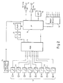
- FIG 2 this indicates the general arrangement of an 8-way concentrator, the major components being a microcontroller 8, multiplexer 9, sensor inputs l0 with respective integrators ll, sample and hold capacitor l2, pulse width modulator l3, and sensor power controller l4.
- 4-way concentrators are the same, except that sensors will be connected only to inputs corresponding to nos.l-4 of an 8-way concentrator.
- the activity of an 8-way concentrator during one scanning period is described as follows, in connection with which reference to Figure 3 will also be useful.
- the microcontroller 8 monitors SO line 6 and is reset to the start of its programme by the silence period between scans. It reads the concentrator address and data identifying it as an 8 or 4-way device from hard-wired option links within the concentrator, detects the tamper status (a binary value) e.g. from an associated microswitch or other tamper sensor, and applies address 0 to the multiplexer 9. The positive edge of each successive clock pulse is detected and the clock count incremented until the individual concentrator address is reached.
- tamper status a binary value
- each sensor input l0 generates a respective analogue voltage from the associated sensor output by means of a resistor network, and inputs to a respective RC integrator ll.
- the multiplexer 9 is also enabled, and thus discharges the integrator at the first sensor input.
- the multiplexer address is incremented so that the first sensor input begins a fresh period of integration and the integrator at the second sensor input is discharged.
- the multiplexer address is incremented again for the next two clock periods, so that by the end of the active period 4 of the concentrator the first four sensor inputs will have been discharged and be at various stages of signal integration.
- the multiplexer address is incremented again and the integrator at the fifth sensor input is discharged.
- the multiplexer address is not then incremented until active period 7, however, so that integration of input 5 is delayed behind input 4 by an extra clock period (to allow insertion of tamper information during the subsequent output phase).
- the process is then continued until by active period l0 all of the sensor inputs have been discharged and are integrating, and the multiplexer is inhibited.
- the eleventh active period the ten-period integration of sensor input l is completed, and the tamper status pulse is also modulated onto the SI line.
- Active period l2 is the start of transmission of sensor data. At the beginning of this period the multiplexer is inhibited and address O selected, the pulse width modulation capacitor is discharged, and the SI driver to the positive rail is turned on. The multiplexer is then enabled for a period of approximately l0 ⁇ s during which it takes a sample from the integration on sensor input l and passes it to the sample and hold capacitor l2 on the input to the pulse width modulator l3. The microcontroller now monitors the output of the pulse width modulator and when that output toggles, indicating that a pulse width corresponding to the sensor input voltage has been produced, the driver to the SI line is driven low. A minimum pulse width of l0% of the clock period is always sent as proof of correct operation. In the event that the modulator output has not toggled by 90% of the clock period the microcontroller truncates the signal on the SI line, indicating a maximum width pulse.
- the multiplexer address is incremented ready for sensor input 2, and the same process as described above is performed during active periods l3, l4, l5, l7, l8, l9 and 20 for the transmission of pulse widths corresponding to the voltages at sensor inputs 2-8 respectively, the tamper information being transmitted again during period l6.
- power to the sensor networks is switched off and the concentrator remains inactive until the next scan, except to monitor the SO line.
- the ability to switch power to the connected sensors only during the active period of the respective concentrator is of advantage in minimising both the overall power-consumption of the system and the power rating of the trunk.
- a 4-way concentrator would emulate the above operation in respect of the integration and data transmission of the first four sensor outputs and the first tamper signal.
- Accurate measurement of each pulse width is necessary if the analogue data is to be sufficiently resolved.
- One method is to use a high speed clock (eg l00 KHz) and an associated counter which counts whenever the input signal is high during the period of a received pulse, thus being less susceptible to line noise than, for example, an edge-triggered arrangement.
- clock pulses broadcast by the controller l on the SO line is for interrogation of the concentrators 2 and for synchronisation of the data returned thereby
- Data for a respective concentrator could be modulated onto those pulses on the SO line which are read by the concentrator during the first half of its active period following recognition of its address, and could be used by the microcontroller at the concentrator for controlling external outputs e.g. for lighting indicator lamps at the concentrator in the event of an alarm or fault indication being received from any of its sensors, and/or for completely unconnected purposes such as the control of building lights or other services.
- this function is illustrated schematically by the LED control l5 and the several external output drivers l6.
- Additional protection can be built into the system to prevent substitution of concentrators by potential intruders.
- a substitute concentrator arranged to give normal readings for all sensor inputs, and to switch over to this substitute in place of a genuine concentrator during the silent period. Then the genuine concentrator would not be observed by the controller and off-normal sensor inputs connected to it would not be detected.
- width-modulate the tamper signals from each concentrator for successive scans in accordance with a predefined repeating sequence, the starting point within which, when the system is activated, is based on unique information within the respective concentrator, (e.g. its address).
- each concentrator is arranged to be active throughout each system scan and to scan its own sensor inputs as described above repetitively during this period (still using the SO clock as timing reference), i.e. not just once per system scan as previously described. If during any one of these multiple scans an off-normal state occurs on any input then that state will be latched within the concentrator and transmitted accordingly when it is that concentrator's turn to put its data onto the SI line.
- An advantage of this is that it becomes possible to detect off-normal sensor inputs of very short duration - in the limit each sensor input can be scanned every 20ms/l6.7ms in the 50Hz and 60Hz systems described.
- multiple scanning within the concentrators enables the address field to be increased and many more concentrators and sensors to be added to the system - although the rate at which the individual concentrators can be scanned by the controller decreases as the size of the system increases, multiple scanning of the sensor inputs within the concentrators means that detection of short off-normal states at the concentrators is still retained and a possible delay of even a few seconds in the transmission of those states from the concentrators to the controller is not generally considered critical.
Landscapes
- Business, Economics & Management (AREA)
- Emergency Management (AREA)
- Physics & Mathematics (AREA)
- General Physics & Mathematics (AREA)
- Alarm Systems (AREA)
Applications Claiming Priority (2)
| Application Number | Priority Date | Filing Date | Title |
|---|---|---|---|
| GB868616276A GB8616276D0 (en) | 1986-07-03 | 1986-07-03 | Data acquisition system |
| GB8616276 | 1986-07-03 |
Publications (2)
| Publication Number | Publication Date |
|---|---|
| EP0251576A2 true EP0251576A2 (de) | 1988-01-07 |
| EP0251576A3 EP0251576A3 (de) | 1989-04-26 |
Family
ID=10600528
Family Applications (1)
| Application Number | Title | Priority Date | Filing Date |
|---|---|---|---|
| EP87305392A Withdrawn EP0251576A3 (de) | 1986-07-03 | 1987-06-17 | Datenerwerbungssystem |
Country Status (5)
| Country | Link |
|---|---|
| US (1) | US4782330A (de) |
| EP (1) | EP0251576A3 (de) |
| AU (1) | AU592458B2 (de) |
| CA (1) | CA1278841C (de) |
| GB (2) | GB8616276D0 (de) |
Cited By (2)
| Publication number | Priority date | Publication date | Assignee | Title |
|---|---|---|---|---|
| EP0521234A3 (en) * | 1991-07-01 | 1995-03-08 | Moore Ind Int Inc | Computerized remote resistance measurement system with fault detection |
| US10052056B2 (en) | 2014-09-01 | 2018-08-21 | Beyond Verbal Communication Ltd | System for configuring collective emotional architecture of individual and methods thereof |
Families Citing this family (11)
| Publication number | Priority date | Publication date | Assignee | Title |
|---|---|---|---|---|
| NO885320L (no) * | 1987-11-30 | 1989-05-31 | Hochiki Co | Brann-alarm system. |
| US5239459A (en) * | 1990-02-05 | 1993-08-24 | General Research Corporation | Automated assessment processor for physical security system |
| US5471194A (en) * | 1993-03-23 | 1995-11-28 | Aritech Corporation | Event detection system with centralized signal processing and dynamically adjustable detection threshold |
| US5534849A (en) * | 1993-08-11 | 1996-07-09 | Sentrol, Inc. | Time multiplexed, false alarm resistant magnetically actuated security system |
| AUPM364594A0 (en) * | 1994-02-02 | 1994-02-24 | Barisic, Sandra | Condition indicating system |
| US6359555B1 (en) * | 1997-04-16 | 2002-03-19 | A.L. Airdata, Inc. | Alarm monitoring and control system and method |
| US6226305B1 (en) * | 1997-11-06 | 2001-05-01 | Mcloughlin John E. | Apparatus multiplexing system |
| US6002996A (en) * | 1997-11-26 | 1999-12-14 | The Johns Hopkins University | Networked sensor system |
| US6560279B1 (en) | 1999-10-25 | 2003-05-06 | John F. Renz | Two wire multiplex data acquisition system with remote unit mode controls |
| GB0002140D0 (en) | 2000-02-01 | 2000-03-22 | Alstom | Improvements in electrical circuits |
| CN106603308A (zh) * | 2017-01-03 | 2017-04-26 | 国网浙江省电力公司宁波供电公司 | 一种用于户表动态注册和台区识别的方法及系统 |
Family Cites Families (17)
| Publication number | Priority date | Publication date | Assignee | Title |
|---|---|---|---|---|
| GB1101122A (en) * | 1964-04-02 | 1968-01-31 | Evershed Vignoles Ltd | Improvements relating to data transmission systems |
| DE2433025A1 (de) * | 1974-07-10 | 1976-01-22 | Bosch Gmbh Robert | Verfahren und vorrichtung zum steuern und kontrollieren von elektrischen schaltvorgaengen, insbesondere in kraftfahrzeugen |
| JPS5244655A (en) * | 1975-10-03 | 1977-04-07 | Sumitomo Chem Co Ltd | Centralized control unit for a gas leak |
| US4294065A (en) * | 1978-04-26 | 1981-10-13 | Parks-Cramer Company | Method and apparatus for facilitating maintenance of spinning machine information system |
| CA1157924A (en) * | 1980-07-15 | 1983-11-29 | Ezequiel Mejia | Information reporting multiplex system |
| JPS58198993A (ja) * | 1982-05-15 | 1983-11-19 | Matsushita Electric Works Ltd | 時分割多重伝送システム |
| JPS58198994A (ja) * | 1982-05-15 | 1983-11-19 | Matsushita Electric Works Ltd | 時分割多重遠隔制御システムの割込処理方式 |
| US4535401A (en) * | 1982-06-30 | 1985-08-13 | Texas Instruments Incorporated | Apparatus and method for providing power from master controller to subcontrollers and data communication therebetween |
| DE3225081A1 (de) * | 1982-07-05 | 1984-01-12 | Siemens AG, 1000 Berlin und 8000 München | Verfahren und einrichtung zur automatischen abfrage des meldermesswerts und der melderkennung in einer gefahrenmeldeanlage |
| JPS5938897A (ja) * | 1982-08-27 | 1984-03-02 | ニツタン株式会社 | 異常監視装置 |
| US4538138A (en) * | 1982-12-17 | 1985-08-27 | American District Telegraph Company | Integrated security system having a multiprogrammed controller |
| JPS59163696A (ja) * | 1983-03-09 | 1984-09-14 | 株式会社日本自動車部品総合研究所 | 電気配線システム |
| FR2550901B1 (fr) * | 1983-08-19 | 1986-08-08 | Protecbat Detection Electro Fs | Procede de transmission de messages entre un poste central et plusieurs postes eloignes |
| DE3332268A1 (de) * | 1983-09-07 | 1985-03-21 | Fa. Aug. Winkhaus, 4404 Telgte | Alarmmeldeanlage |
| JPS60186994A (ja) * | 1984-03-05 | 1985-09-24 | ホーチキ株式会社 | 火災感知器 |
| DE19834854C2 (de) * | 1998-08-01 | 2000-06-29 | Karlsruhe Forschzent | Quasi-hemisphärischer Fabry-Perot-Resonator und Verfahren zum Betreiben desselben |
| JP2005038414A (ja) * | 2003-06-30 | 2005-02-10 | Fuji Photo Film Co Ltd | ファイル管理プログラム、ファイル管理方法、ファイル管理装置、撮像装置及び記録媒体 |
-
1986
- 1986-07-03 GB GB868616276A patent/GB8616276D0/en active Pending
-
1987
- 1987-06-17 EP EP87305392A patent/EP0251576A3/de not_active Withdrawn
- 1987-06-17 GB GB8714238A patent/GB2192298B/en not_active Expired - Fee Related
- 1987-06-25 US US07/066,910 patent/US4782330A/en not_active Expired - Fee Related
- 1987-07-02 CA CA000541101A patent/CA1278841C/en not_active Expired - Fee Related
- 1987-07-03 AU AU75207/87A patent/AU592458B2/en not_active Ceased
Cited By (2)
| Publication number | Priority date | Publication date | Assignee | Title |
|---|---|---|---|---|
| EP0521234A3 (en) * | 1991-07-01 | 1995-03-08 | Moore Ind Int Inc | Computerized remote resistance measurement system with fault detection |
| US10052056B2 (en) | 2014-09-01 | 2018-08-21 | Beyond Verbal Communication Ltd | System for configuring collective emotional architecture of individual and methods thereof |
Also Published As
| Publication number | Publication date |
|---|---|
| GB2192298A (en) | 1988-01-06 |
| US4782330A (en) | 1988-11-01 |
| EP0251576A3 (de) | 1989-04-26 |
| AU7520787A (en) | 1988-01-07 |
| CA1278841C (en) | 1991-01-08 |
| GB8714238D0 (en) | 1987-07-22 |
| GB8616276D0 (en) | 1986-08-13 |
| AU592458B2 (en) | 1990-01-11 |
| GB2192298B (en) | 1990-12-19 |
Similar Documents
| Publication | Publication Date | Title |
|---|---|---|
| CA1278841C (en) | Data acquisition system | |
| US4454509A (en) | Apparatus for addressably controlling remote units | |
| US4206449A (en) | Multiple sensor intrusion alarm system | |
| US4540890A (en) | System for selectively addressing electrical control signals from a control unit to a plurality of remote units | |
| US4612534A (en) | Method of transmitting measuring values in a monitoring system | |
| US4056684A (en) | Surveillance system | |
| US4672374A (en) | System for bilateral communication of a command station with remotely located sensors and actuators | |
| US5089809A (en) | Remote indication of appliance status | |
| US4352992A (en) | Apparatus for addressably controlling remote units | |
| EP0266392A1 (de) | Lokales regelungssystem für haushaltsgeräte und warngeräte | |
| EP0050624A1 (de) | Elektrisches überwachungs-, steuer- und datenaufnahmesystem. | |
| JPH0632144B2 (ja) | 環境異常警報装置 | |
| EP0770250A4 (de) | Rauchmeldersystem mit digitalanzeige | |
| US4459672A (en) | Decoder | |
| JP4090038B2 (ja) | 火災報知設備 | |
| RU2250566C2 (ru) | Способ передачи электрических сигналов | |
| JPS63254599A (ja) | 情報監視制御システム | |
| JPS61133499A (ja) | 複数住戸の相互監視装置 | |
| JP4090037B2 (ja) | 火災報知設備 | |
| JP2858266B2 (ja) | 発報レベル切換機能を有した火災報知システム | |
| RU2155383C1 (ru) | Способ обмена информацией в системе тревожной сигнализации | |
| RU2226002C1 (ru) | Устройство объектовое | |
| SU1034058A1 (ru) | Терминал дл устройства тревожной сигнализации | |
| JP2552272B2 (ja) | 自動火災報知装置 | |
| EP0130164A2 (de) | Gerät zur Geräuschimmunitätsanpassung eines tonfrequenzselektiven Empfängers |
Legal Events
| Date | Code | Title | Description |
|---|---|---|---|
| PUAI | Public reference made under article 153(3) epc to a published international application that has entered the european phase |
Free format text: ORIGINAL CODE: 0009012 |
|
| AK | Designated contracting states |
Kind code of ref document: A2 Designated state(s): BE CH DE ES FR IT LI NL |
|
| PUAL | Search report despatched |
Free format text: ORIGINAL CODE: 0009013 |
|
| AK | Designated contracting states |
Kind code of ref document: A3 Designated state(s): BE CH DE ES FR IT LI NL |
|
| 17P | Request for examination filed |
Effective date: 19891016 |
|
| 17Q | First examination report despatched |
Effective date: 19910830 |
|
| STAA | Information on the status of an ep patent application or granted ep patent |
Free format text: STATUS: THE APPLICATION IS DEEMED TO BE WITHDRAWN |
|
| 18D | Application deemed to be withdrawn |
Effective date: 19921210 |
|
| RIN1 | Information on inventor provided before grant (corrected) |
Inventor name: PATEY, RONALD ERNEST RUSSELL Inventor name: TINDALL, DAVID WILLIAM |