EP0251641A1 - Récipients pour le traitement de surfaces d'articles - Google Patents
Récipients pour le traitement de surfaces d'articles Download PDFInfo
- Publication number
- EP0251641A1 EP0251641A1 EP87305555A EP87305555A EP0251641A1 EP 0251641 A1 EP0251641 A1 EP 0251641A1 EP 87305555 A EP87305555 A EP 87305555A EP 87305555 A EP87305555 A EP 87305555A EP 0251641 A1 EP0251641 A1 EP 0251641A1
- Authority
- EP
- European Patent Office
- Prior art keywords
- door
- container
- container assembly
- aperture
- cam
- Prior art date
- Legal status (The legal status is an assumption and is not a legal conclusion. Google has not performed a legal analysis and makes no representation as to the accuracy of the status listed.)
- Granted
Links
- 238000004381 surface treatment Methods 0.000 title claims abstract 5
- 230000007246 mechanism Effects 0.000 claims abstract description 10
- 230000000717 retained effect Effects 0.000 claims description 5
- 230000002093 peripheral effect Effects 0.000 claims description 4
- 241000282472 Canis lupus familiaris Species 0.000 description 11
- 238000007747 plating Methods 0.000 description 7
- 230000008901 benefit Effects 0.000 description 6
- 239000012530 fluid Substances 0.000 description 6
- 238000009713 electroplating Methods 0.000 description 5
- 238000000034 method Methods 0.000 description 5
- 230000008569 process Effects 0.000 description 4
- 230000009471 action Effects 0.000 description 3
- 238000004519 manufacturing process Methods 0.000 description 3
- 229910000831 Steel Inorganic materials 0.000 description 2
- 238000010276 construction Methods 0.000 description 2
- 230000000694 effects Effects 0.000 description 2
- 239000000463 material Substances 0.000 description 2
- 229920003023 plastic Polymers 0.000 description 2
- 239000004033 plastic Substances 0.000 description 2
- 239000010959 steel Substances 0.000 description 2
- 238000005303 weighing Methods 0.000 description 2
- 230000004075 alteration Effects 0.000 description 1
- 238000004140 cleaning Methods 0.000 description 1
- 238000005260 corrosion Methods 0.000 description 1
- 230000007797 corrosion Effects 0.000 description 1
- 230000007423 decrease Effects 0.000 description 1
- 238000013461 design Methods 0.000 description 1
- 238000009826 distribution Methods 0.000 description 1
- 238000003780 insertion Methods 0.000 description 1
- 230000037431 insertion Effects 0.000 description 1
- 150000002500 ions Chemical class 0.000 description 1
- 238000003754 machining Methods 0.000 description 1
- 230000014759 maintenance of location Effects 0.000 description 1
- 230000013011 mating Effects 0.000 description 1
- 230000005012 migration Effects 0.000 description 1
- 238000013508 migration Methods 0.000 description 1
- 238000012986 modification Methods 0.000 description 1
- 230000004048 modification Effects 0.000 description 1
- 230000000135 prohibitive effect Effects 0.000 description 1
- 238000003908 quality control method Methods 0.000 description 1
- 230000002787 reinforcement Effects 0.000 description 1
- 238000005096 rolling process Methods 0.000 description 1
- 238000005728 strengthening Methods 0.000 description 1
- 238000003466 welding Methods 0.000 description 1
Images


Classifications
-
- C—CHEMISTRY; METALLURGY
- C25—ELECTROLYTIC OR ELECTROPHORETIC PROCESSES; APPARATUS THEREFOR
- C25D—PROCESSES FOR THE ELECTROLYTIC OR ELECTROPHORETIC PRODUCTION OF COATINGS; ELECTROFORMING; APPARATUS THEREFOR
- C25D17/00—Constructional parts, or assemblies thereof, of cells for electrolytic coating
- C25D17/16—Apparatus for electrolytic coating of small objects in bulk
-
- C—CHEMISTRY; METALLURGY
- C25—ELECTROLYTIC OR ELECTROPHORETIC PROCESSES; APPARATUS THEREFOR
- C25D—PROCESSES FOR THE ELECTROLYTIC OR ELECTROPHORETIC PRODUCTION OF COATINGS; ELECTROFORMING; APPARATUS THEREFOR
- C25D17/00—Constructional parts, or assemblies thereof, of cells for electrolytic coating
- C25D17/16—Apparatus for electrolytic coating of small objects in bulk
- C25D17/18—Apparatus for electrolytic coating of small objects in bulk having closed containers
- C25D17/20—Horizontal barrels
-
- C—CHEMISTRY; METALLURGY
- C23—COATING METALLIC MATERIAL; COATING MATERIAL WITH METALLIC MATERIAL; CHEMICAL SURFACE TREATMENT; DIFFUSION TREATMENT OF METALLIC MATERIAL; COATING BY VACUUM EVAPORATION, BY SPUTTERING, BY ION IMPLANTATION OR BY CHEMICAL VAPOUR DEPOSITION, IN GENERAL; INHIBITING CORROSION OF METALLIC MATERIAL OR INCRUSTATION IN GENERAL
- C23G—CLEANING OR DE-GREASING OF METALLIC MATERIAL BY CHEMICAL METHODS OTHER THAN ELECTROLYSIS
- C23G3/00—Apparatus for cleaning or pickling metallic material
Definitions
- the present invention pertains to apparatus for treating articles of manufacture. More particularly, the invention relates to doors and closures for treatment containers or barrels which may, for example, be adapted to be disposed in a tank of treating fluid.
- the invention finds particular application in the art of electroplating and will be described with particular reference thereto. However, the invention is also applicable for cleaning, phosphating, rinsing and other treating operations.
- a conventional plating barrel is filled with particulate workpieces or items to be plated or treated and is immersed in an electroplating or other highly corrosive treating fluid.
- the barrel is rotated within a tank of the treating fluid, whereby the items being treated cascade or tumble over each other in the interior of the barrel.
- the barrel interior is typically filled to approximately one-third to one-half of its volume and generally holds workpieces collectively weighing over one hundred pounds (45.4 kg) and, on certain occasions, holding workpieces collectively weighing as much as five hundred pounds (227 kg) or more.
- the barrels must be sufficiently durable and are constructed of a material adapted to withstand the usually corrosive effects of the treating fluid. Selected plastics have been used with commercial success.
- the barrel has a generally circular sidewall and a pair of opposed flat head ends or endwalls defining a work cavity therein.
- the cylindrically shaped barrel is formed of a plurality of panel members arranged in a hexagonal or octagonal relationship and secured by welding to the heads.
- One of the panels is left out of the welded arrangement and adapted or modified for selective removal and thereby function as a door.
- the removable panel provides access to the interior work cavity. Due to the extreme weight and various workpiece sizes subject to the treating process, a secure and close fitting arrangement is required between the door and the remainder of the barrel.
- the closure mechanism which holds the door closed must be sufficiently strong to withstand the weight of the cascading workpieces contained therein, sufficiently corrosion-resistant to withstand the treating fluids, and easy to operate.
- US-A- 2,886,505 illustrates a conventional clamping arrangement for holding a door in a closed position.
- the door is substantially similar to the remaining panels defining the sidewall of the generally cylindrical container.
- Still other clamping arrangements are illustrated in US-A- 912,041 and US-A- 2,843,979.
- the apparatus described in both of these patents requies direct operator assistance in fastening and clamping the door in fixed, covering relation with the aperture and the remainder of the barrel.
- US-A- 3,507,529 and US-A- 3,583,,739 are both directed to a door assembly for a plating barrel.
- electroplating small workpieces such as washers or the like
- the present invention contemplates a new and improved door opening and closing apparatus for treatment barrels which provides an automatic "hands-off" operation along with the benefits of a close fitting recessed door arrangement.
- a simplified and economical automatic door assembly is provided for a treatment barrel or the like.
- a rotatable barrel or container assembly comprises a container having opposed head ends held in spaced relation by a side member and defining a work cavity for receipt of the workpieces, an aperture being provided in a minor portion of said side member for introduction and removal of workpieces to and from said work cavity, and a door for opening and closing said aperture, characterised by a mechanism for imparting generally arcuate movement and generally radial movement to advance and retract said door between a first open position and a second closed position relative to said aperture.
- the movement-imparting mechanism includes a cam slot and cam follower arrangement.
- the door is provided with means for allowing a generally radial movement thereof while remaining operatively connected to the container.
- the door includes an end plate extending generally perpendicularly from a longitudinal portion of the door.
- the endplate includes an elongated cut-out adapted for sliding engagement with a trunnion operatively associated with the container.
- locking means are provided to selectively maintain the door in a locked open or closed position.
- two push blocks are provided and adapted for engagement with the door to selectively rotate the container with the door.
- One advantage of the invention is found in the simplified actuating mecahnism for the door.
- Another advantage of the invention resides in the adaptability and compatibility with existing automatic and manual manufacturing processes.
- Yet another advantage of the invention resides in the automatic "hands-off" control of the door and resultant safety features associated therewith.
- Yet another advantage of the invention is found in the reduced labour costs of manufacturing and operation of the container assembly.
- a support structure A supports a container assembly B which is commonly referred to as a treatment or plating barrel assembly.
- the support structure A is adapted to be supported across a tank or bath of treating solution (not shown) or a series of treating tanks if so desired.
- the container assembly is selectively immersed in the treating tank for treatment of workpieces retained in the container assembly. Further discussion of the overall plating process is unnecessary to an understanding of the present invention.
- the support structure A includes an elongated channel member 10 which is connected at its ends to downwardly extending hanger arms or legs 12,14.
- a drive means such as an electric motor or the like (not shown) is adapted to drivingly engage drive shaft 16 and drive gears 18 disposed adjacent the ends thereof.
- An idler head 20 is interposed between each drive gear 18 and a respective driven gear which will be described in greater detail below.
- An identical drive gear and idler gear arrangement is arranged at each end of the container assembly and provides simultaneous, synchonized drive of the assembly at opposed ends. Also, alternative drive means may be employed.
- a container such as a barrel or drum 30, includes a generally cylindrical sidewall 32 extending longitudinally between spaced end members or head ends 34,36.
- the sidewall may be formed as a continuous structure, or preferably, is formed from a plurality of planar members 38 arranged in a hexagonal or octagonal relationship.
- the term "generally cylindrical container” will be understood to include any of these defined structural relationships.
- the container is rotatable supported between hanger arms 12 and 14 and extends in generally parallel relation with the channel member 10.
- the sidewall 32 is preferably of perforated construction to allow treatment fluid to readily pass through the sidewall and, if used for electroplating, allow electric current flow.
- An aperture or opening 40 is defined in a minor portion of the side wall 32.
- one of the panels is removed or left out of the structure to define the aperture 40.
- the aperture provides for ingress to and egress from a work cavity or central chamber 42.
- the aperture is of sufficient size to easily enable insertion and removal of the workpieces into and from the work cavity 42.
- the aperture comprises approximately 1/6 of the total surface area of the container, although other dimensions and ratios can be used with equal success.
- a door 44 includes an elongated portion 46 and a pair of radially extending end plates 48,50 as further illustrated in Fig.3.
- the elongated portion 46 is designed to completely cover the aperture in a closed position while the end plates 48,50 are disposed axially outwards of the head ends 34,36 for close fitting relation therewith.
- the elongated portion 46 of the door may include longitudinally extending strenghthening members 52, such as steel or the like, encapsulated within the plastic material of the door when corrosive solutions are involved. The strenghthening members 52 enhance the rigidity of the door.
- a driven gear 60 is disposed at one end of the container 30.
- a similar driven gear 62 is operatively disposed at the other end of the container. Therefore, the numerals and description of the various elements and relationships of driven gear 62 will apply equally to driven gear 60 unless particularly noted otherwise.
- the gear 62 has peripherally arranged drive teeth 64 adapted for meshing engagement with peripheral teeth on idler gear 20.
- An interior face 66 of the gear 62 is disposed in facing relation with the head end 36 of the container while the interior face of gear 60 is in facing relation with head end 34.
- the interior face 66 of the gear 62 is clearly illustrated in Fig.2. It contains a cam slot or groove 68 having a predetermined pattern.
- a first portion of the cam slot defines an arcuate length 70 at a generally constant radius from a central opening or mounting aperture 72.
- a crest portion 74 is interposed between the constant radius portion 70 and a portion 76 of varying radius.
- the crest portion 74 defines a path which extends radially outwardly from the constant radius portion while the radially varying portion 76 defines a sloping path which spirals inwardly towards mounting aperture 72.
- the drive gear 62 also includes first and second push dogs or door locks 84,86.
- first and second push dogs or door locks 84,86 The precise function of the combination push dogs/door locks will be described in further detail hereinbelow.
- FIG.3 a view of the cylindrical container head end 36 and a door end plate 50 is illustrated.
- the head end 34 and door end plate 48 disposed at the left-hand portion of the container in Fig.1 are of identical construction and function in a similar manner as head end 36 and end plate 50 unless noted otherwise.
- the head end is of generally circular configuration and includes first and second push blocks 88,90 extending axially outwardly therefrom.
- the push blocks 88,90 are arranged adjacent a peripheral portion of the head end 36 and positioned at a preselected angular configuration adapated to enable the door-open and door-closed positions to be achieved, as will become more apparent below.
- a central hub or trunnion 92 is closely received through the head end 36 through a central aperture (not shown) and the external surface of the trunnion co-operates with a conventional bushing or bearding 93, three of which are utilized in the preferred embodiment for rotary movement of the container assembly therearound.
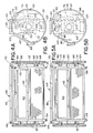
- End plate 50 is designed for abutting engagement with push block 90 in the fully open position as shown in Fig.4B while Fig.3 illustrates engagement with push block 88 in the open position.
- a cam follower 94 extends axially outwardly from each end plate 48,50 towards respective gears 60,62.
- the cam follower 94 of each end plate is designed for receipt in the respective cam slot 68 in the inner face of drive gears 60,62.
- the co-operating end plates and gears define a means for imparting generally arcuate movement and generally radial movement to the door as will be detailed below.
- the cam slot 68 and cam follower 94 define a cam means for actuating movement of the door.
- Each cam follower includes a high-density, self-lubricating member 96 peripherally arranged on the cam follower to facilitate sliding/rolling contact with the cam slot.
- an elongated generally rectangular aperture 102 is provided in each of the end plates and slidingly receives a slide block 104 therein.
- the slide block 104 and elongated aperture 102 have a co-operating tongue and groove arrangement 106 adapted for ease of radial movement of the slide block relative to the end plate.
- the slide block 104 has a central aperture 108 with bearing 93 designed for rotative mounting on trunnion 92.
- the end plate 50 also has door locking notches 110, 112, 114 and 116.
- the door locking notches are peripherally arranged on the end plate and adapted for alternately receiving the combination push dogs/door locks 84,86 therein. Further, closing member 120 is positioned at the base of the end plate 50 at an area distally arranged from the elongated portion 46 of the door.
- the slide block 104 In mounting the door onto trunnion 92, the slide block 104 is initially positioned on the trunnion adjacent head end 36 of the container. Next, the end plate 50, with the closing member 120 removed therefrom, is radially positioned over the slide block. The co-operating tongue and groove engagement between the slide block and end plate facilitate mounting. The closing member 120 is thereafter secured to the end plate to limit the radially outward movement of the door relative to the container 30. The closing member also reinforces the end plate and retains alignment of the tongue/groove arrangement 106.
- the slide block remains stationary relative to the trunnion and rotated with the door. Nevertheless, the remainder of the end plate 50 undergoes radial inward and outward movement relative to the slide block as a result of the cam-actuated movement. In this manner, the door 44 moves from a radially outer open position (see Fig.4B) to a radially inner closed position (see Fig.6B).
- the push blocks 88,90 are peripherally arranged on head 36 of the container assembly. More specifically, the circumferential arc length between the push blocks 88,90 is approximately twice the width of door 44. Thus, in the illustrated open position of Figs.4A and 4B, the aperture 40 is completely exposed and end plate 50 is in abutting engagement with push block 90.
- the head end 36 includes a radially recessed portion 122 (Fig.3) adapted to receive the elongated portion 46 of the door in the open position of the door. As will become more apparent, this assures a compact arrangement of the door with the container 30 in an open position and further prevents any interference with the drive shaft 16 or other portion of the support structure. This also provides compactness of the entire container assembly.
- Figs. 4A and 4B the open position of the door relative to the container and, specifically, aperture 40 will be described in detail.
- This is also known as the load position of the container assembly in which the aperture 40 is generally facing angularly upwardly for receipt of particulate workpieces.
- This position also assists an operator in viewing the loading of the container.
- the door 44 abuttingly engages push block 90 and is positioned at a radially outer position i.e, the slide block is closely adjacent the closing member 120 in end plate 50.
- the combination push dog/door lock 86 is received in the door locking notch 110.
- the combination push dog/door lock 84 is received in door locking notch 114.
- the cam follower 94 is received in the constant radius portion 70 of the cam slot.
- the cam slot and cam follower of the gear and door, respectively, provide for relative positioning both radially and arcuately between the container and the door.
- the container In the open position, the container is loaded with particulate workpieces through aperture 40.
- the aperture is sufficiently large to permit quick loading of a large number of workpieces.
- cam follower 94 Upon engagement of the door with push block 88, cam follower 94 is advanced radially outwardly over the crest portion of the cam slot. Accordingly, the door moves radially outwardly with the aperture 40 and will next undergo a radially inward movement.
- the door has moved radially inwardly into a seated position and covers the aperture 40. Any further counter-clockwise movement of the gear causes simultaneous rotation of the door and the container together. This would correspond to the loaded condition of the container assembly in which it undergoes a submersion and tumbling or cascading of the workpieces retained in the work cavity.
- the container Upon completion of the predetermined duration in the treatment tank, the container is locked in place and removed from the tank. Further rotation in a counter-clockwise direction orients the container essentially as shown in Fig.6B.
- the drive gears are now rotated in a clockwise manner as shown until the door opens relative to the aperture in a reverse manner from that described above.
- the door moves radially outwardly as the cam follower 94 proceeds through the radially varying portion 76 of the cam slot towards the crest portion. Once the cam follower reaches the crest portion 74 of the cam slot, the gear and door rotate together away from push block 88 and towards push block 90.
- the cam follower Upon abutting engagement with the push block 90, the cam follower passes over the crest portion and into the constant radius portion 70 of the cam slot. Accordingly, during this procedure, the combination push dogs/door locks 84,86 have also moved from engagement with locking notches 112,116 to the locking notches 110,114. At this point, the aperture is completely uncovered and further clockwise rotation, as shown, of the cylindrical container 30 enables emptying the contents from the work cavity. That is, the aperture is rotated in a clockwise direction until it faces downwardly. Once the contents are emptied, the clockwise rotation continues until the aperture is positioned in an angularly upward position for the next loading of workpieces (Fig.4A).
- an operator of the plating container 30 can be located in a "hands-off" position where he is safely clear of the loading and unloading operation of the barrel.
- This arrangement also eliminates any need for springs or clamping arrangements to retain the door in a closed position with the aperture.
- the motor is only required to be of the reversing type and no special controls are required.
- the complete opening and closing action of the door is governed by the rotation of the gears and the cam follower tracking in the cam slot along with the door and push block engagement as well as the combination push dog/door lock and end bracket engagement. Further, only the weight of the door is loaded on the cam follower and cam slot.
- the modified door 44 ⁇ includes an elongated portion 46 ⁇ reinforced by use of encapsulated or encased strengthening members 52 ⁇ which extend along the longitudinal length of the door.
- Opposed end plates 48 ⁇ ,50 ⁇ are disposed in a generally perpendicular relation with respect to the elongated portion 46 ⁇ .
- a cam follower 94 ⁇ extends axially outwardly from each of the end plates 48 ⁇ ,50 ⁇ .
- each end plate is designed for co-operating relation with an inwardly facing cam slot on an interior face of opposed driven gears, only one of which is shown for ease of illustration.
- an elongated aperture receives a slide block for permitting radial movement of the door with respect to trunnion 92.
- the preferred arrangement is designated for extreme wear conditions so that the wear resulting from the radially inward and outward movement of the door is dispersed over the tongue and groove arrangement of the slide block and end plate.
- an elongated aperture 102 ⁇ is defined in each of the end plates and has a generally elliptical configuration.
- the minor axis of the ellipse generally conforms to the outer diameter of raised portion 122 of the drive gear 62 ⁇ .
- wear between the relatively moving parts is not distributed over as great a surface area. Nonetheless, this arrangement is more than satisfactory for most industrial applications and significantly decreases the complexity as well as machining and assembly costs.
- the end plates still utilize door locking notches 110 ⁇ , 112 ⁇ , 114 ⁇ , and 116 ⁇ and encased steel reinforcement 52 ⁇ .
- the modified door arrangement of Fig.7 functions in approximately the same manner as that described with the preferred embodiment of Figs. 1 to 6.
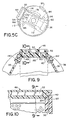
- the trunnion 92 is particularly illustrated in Fig.8 and, as described above, is fixedly mounted to a support hanger arm 12 or 14. As illustrated, the trunnion has a generally cylindrical configuration with an aperture extending generally longitudinally therethrough.
- the aperture 124 is centrally positioned at a first or outer end 126 but is eccentrically disposed at a second or inner face 128.
- the trunnion aperture is designed to receive a dangler therethrough. The dangler will thereby maintain a generally downwardly angled disposition and not migrate appreciably upwardly with workpieces during rotation of the container, notwithstanding virtually constant impinging contact with the workpieces.
- the danglers when used for electroplating the danglers are provided to supply the high current or throwing power necessary to effect plating of the workpieces.
- An electric current induced through the danglers charges the workpieces through contact therewith.
- the container As the container is rotated, the workpieces to be plated are continuously exposed to a relatively uniform high current field by repeated rotation and exposure to one of the danglers or by conduction through other workpieces. The presence of the electric current caused migration of the plating ions to the workpieces.
- the elongated portion 46 of the door is of rebated design so that it fully seats within the aperture 40.
- a pair of axially extending door ribs 140,142 receive two perforated panels 144,146 defining a portion of the container sidewall.
- the ribs each define a recessed step portion 148,150 which, in turn, matingly receives a stepped or rebated lower surface 152 of the door.
- the step portions 148,150 abuttingly support the door so that particulate workpieces in the container are retained therein.
- the elongated portion 46 of the door also includes an axial step surface 154 which closely accommodates a head end.
- the stepped mating configuration facilitates retention of the workpieces in the work cavity.
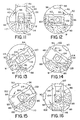
- FIG. 11 the dumping sequence of the container is shown.
- the container has completed the treatment process of the workpieces W and the aperture 40 is positioned in an angularly upward loading position.
- the door opening process is completed and further clockwise rotation of the container as shown orients the aperture in a downward position.
- the workpieces have a tendency to "climb" along the left-hand portion of the work cavity as rotation of the container continues.
- the workpieces tend to exert a counter-clockwise torque or rotation on the container which is opposed to the clockwise rotation of the gear.
- the combination push dogs/door locks tightly engage the door locking notches 110,114 and the end plate abuts push block 90.
- Figs. 14 to 16 depicts the tumbling action of the workpieces once the container has been loaded, the door closed over the aperture, and the container rotated in a counter-clockwise direction as shown for treating in a treatment tank.
- the workpieces migrate up the right-hand side of the work cavity thereby imposing a clockwise torque or rotation on the container.
- the shift in weight to an uneven distribution eccentrically positions the centroid of the workpieces towards the right-hand portion of the container in relation to the axis of rotation defined through the trunnion.
- the combination push dogs/locking pins now tightly engage the door locking notches 112,116 and the end plate abuts push block 88.
- the open position and the closed position of the door are enhanced by the force and torque exerted by the workpieces.
Landscapes
- Chemical & Material Sciences (AREA)
- Engineering & Computer Science (AREA)
- Chemical Kinetics & Catalysis (AREA)
- Materials Engineering (AREA)
- Metallurgy (AREA)
- Organic Chemistry (AREA)
- Electrochemistry (AREA)
- Mechanical Engineering (AREA)
- General Chemical & Material Sciences (AREA)
- Cleaning And De-Greasing Of Metallic Materials By Chemical Methods (AREA)
- Coating With Molten Metal (AREA)
- Chemically Coating (AREA)
- Sealing Of Jars (AREA)
- Electroplating Methods And Accessories (AREA)
- Treatments Of Macromolecular Shaped Articles (AREA)
- Physical Vapour Deposition (AREA)
- Spray Control Apparatus (AREA)
- Coating Apparatus (AREA)
Priority Applications (1)
| Application Number | Priority Date | Filing Date | Title |
|---|---|---|---|
| AT87305555T ATE71673T1 (de) | 1986-06-24 | 1987-06-23 | Behaelter zur oberflaechenbehandlung von gegenstaenden. |
Applications Claiming Priority (2)
| Application Number | Priority Date | Filing Date | Title |
|---|---|---|---|
| US06/877,808 US4736868A (en) | 1986-06-24 | 1986-06-24 | Plating barrel door apparatus |
| US877808 | 1986-06-24 |
Publications (2)
| Publication Number | Publication Date |
|---|---|
| EP0251641A1 true EP0251641A1 (fr) | 1988-01-07 |
| EP0251641B1 EP0251641B1 (fr) | 1992-01-15 |
Family
ID=25370770
Family Applications (1)
| Application Number | Title | Priority Date | Filing Date |
|---|---|---|---|
| EP87305555A Expired - Lifetime EP0251641B1 (fr) | 1986-06-24 | 1987-06-23 | Récipients pour le traitement de surfaces d'articles |
Country Status (8)
| Country | Link |
|---|---|
| US (1) | US4736868A (fr) |
| EP (1) | EP0251641B1 (fr) |
| JP (1) | JPS634098A (fr) |
| KR (1) | KR940010460B1 (fr) |
| AT (1) | ATE71673T1 (fr) |
| AU (1) | AU589017B2 (fr) |
| CA (1) | CA1298237C (fr) |
| DE (1) | DE3776004D1 (fr) |
Cited By (3)
| Publication number | Priority date | Publication date | Assignee | Title |
|---|---|---|---|---|
| GB2203449A (en) * | 1987-02-02 | 1988-10-19 | Stein Atkinson Strody Ltd | Metal finishing barrel |
| FR2852332A1 (fr) * | 2003-03-11 | 2004-09-17 | T L T | Fut d'electrolyse |
| CN103952750A (zh) * | 2014-05-20 | 2014-07-30 | 张军 | 自开盖电镀滚桶 |
Families Citing this family (6)
| Publication number | Priority date | Publication date | Assignee | Title |
|---|---|---|---|---|
| FR2613955B1 (fr) * | 1987-04-14 | 1989-06-16 | Perrot Yvan | Perfectionnements aux machines industrielles de traitement a cuve tournante |
| US5733040A (en) * | 1996-06-27 | 1998-03-31 | Singleton Corporation | Latch assembly for barrels |
| WO2000000669A1 (fr) * | 1998-06-26 | 2000-01-06 | Ernst Eichholzer | Systeme a tambours destine a recevoir des produits en vrac aux fins de traitement de surface |
| KR101279526B1 (ko) * | 2012-09-04 | 2013-06-28 | 주식회사 광성금속 | 배럴식 전기도금장치 |
| US9637307B2 (en) | 2013-01-22 | 2017-05-02 | Spokane Industries | Sliding-locking below liquid manway door |
| US11168442B1 (en) | 2020-07-08 | 2021-11-09 | Valmet, Inc. | Through-air apparatus with tension cam mechanism |
Citations (2)
| Publication number | Priority date | Publication date | Assignee | Title |
|---|---|---|---|---|
| AT310523B (de) * | 1971-02-11 | 1973-10-10 | Langhein & Co Appbau | Galvanisiervorrichtung |
| AT361754B (de) * | 1978-08-30 | 1981-03-25 | Linnhoff Ohg Wilhelm | Einrichtung zur fluessigkeitsbehandlung von massenteilen in einer rotierenden trommel |
Family Cites Families (18)
| Publication number | Priority date | Publication date | Assignee | Title |
|---|---|---|---|---|
| US912041A (en) * | 1904-02-19 | 1909-02-09 | Conkling Company | Washer cylinder-door. |
| US2556490A (en) * | 1945-08-27 | 1951-06-12 | Avco Mfg Corp | Washing by intermittent high and low speed rotation |
| US2843979A (en) * | 1955-11-23 | 1958-07-22 | Lupo Joseph | Tumbling barrels and screens therefor |
| US2886505A (en) * | 1956-04-20 | 1959-05-12 | Singleton Company | Plating apparatus |
| US3507529A (en) * | 1967-02-23 | 1970-04-21 | Gs Equipment Co | Covers for plating barrels and the like |
| US3484360A (en) * | 1968-11-04 | 1969-12-16 | Paul W Sandrock | Closure for plating drum |
| JPS507013B1 (fr) * | 1969-07-03 | 1975-03-20 | ||
| US3560036A (en) * | 1969-08-25 | 1971-02-02 | Stutz Co The | Latch for the cover of an electrical plating rotating barrel |
| US3583739A (en) * | 1969-10-29 | 1971-06-08 | Gs Equipment Co | Covers for plating barrels and the like |
| BE772258A (nl) * | 1971-09-07 | 1972-01-17 | Hooge Fm N V D | Inrichting voor het automatisch openen respektievelijk sluiten van een gebogen schuifdeur of dergelijke ten opzichte van een koncentrische opening. |
| US3850737A (en) * | 1972-12-26 | 1974-11-26 | Trw Inc | Electroplating barrel with internal anode and cathode |
| US3861654A (en) * | 1973-11-28 | 1975-01-21 | Albert Singleton | Door opening and closing apparatus for tumbling barrel |
| US3944189A (en) * | 1973-11-28 | 1976-03-16 | Albert Singleton | Door opening and closing apparatus for tumbling barrel |
| DE2557592A1 (de) * | 1975-12-20 | 1977-06-30 | Linnhoff Ohg Wilhelm | Be- und entladestation fuer die chemische und/oder elektrochemische behandlung von massenteilen |
| US4422774A (en) * | 1981-03-20 | 1983-12-27 | The Harshaw Chemical Company | Metal finishing barrel apparatus |
| US4467940A (en) * | 1981-03-20 | 1984-08-28 | Harshaw/Filtrol Partnership | Metal finishing barrel having a sliding closure |
| US4445993A (en) * | 1981-10-29 | 1984-05-01 | Stutz Company | Laser perforated plating barrel and method of constructing the same |
| US4479371A (en) * | 1982-12-13 | 1984-10-30 | Ellis Corporation | Washing and extracting machine |
-
1986
- 1986-06-24 US US06/877,808 patent/US4736868A/en not_active Expired - Lifetime
-
1987
- 1987-06-17 AU AU74407/87A patent/AU589017B2/en not_active Ceased
- 1987-06-22 CA CA000540280A patent/CA1298237C/fr not_active Expired - Lifetime
- 1987-06-23 EP EP87305555A patent/EP0251641B1/fr not_active Expired - Lifetime
- 1987-06-23 AT AT87305555T patent/ATE71673T1/de active
- 1987-06-23 DE DE8787305555T patent/DE3776004D1/de not_active Expired - Fee Related
- 1987-06-24 KR KR1019870006428A patent/KR940010460B1/ko not_active Expired - Fee Related
- 1987-06-24 JP JP62157470A patent/JPS634098A/ja active Pending
Patent Citations (2)
| Publication number | Priority date | Publication date | Assignee | Title |
|---|---|---|---|---|
| AT310523B (de) * | 1971-02-11 | 1973-10-10 | Langhein & Co Appbau | Galvanisiervorrichtung |
| AT361754B (de) * | 1978-08-30 | 1981-03-25 | Linnhoff Ohg Wilhelm | Einrichtung zur fluessigkeitsbehandlung von massenteilen in einer rotierenden trommel |
Cited By (4)
| Publication number | Priority date | Publication date | Assignee | Title |
|---|---|---|---|---|
| GB2203449A (en) * | 1987-02-02 | 1988-10-19 | Stein Atkinson Strody Ltd | Metal finishing barrel |
| FR2852332A1 (fr) * | 2003-03-11 | 2004-09-17 | T L T | Fut d'electrolyse |
| CN103952750A (zh) * | 2014-05-20 | 2014-07-30 | 张军 | 自开盖电镀滚桶 |
| CN103952750B (zh) * | 2014-05-20 | 2016-07-06 | 张军 | 自开盖电镀滚桶 |
Also Published As
| Publication number | Publication date |
|---|---|
| KR880000626A (ko) | 1988-03-28 |
| AU7440787A (en) | 1988-01-07 |
| US4736868A (en) | 1988-04-12 |
| DE3776004D1 (de) | 1992-02-27 |
| CA1298237C (fr) | 1992-03-31 |
| KR940010460B1 (ko) | 1994-10-22 |
| ATE71673T1 (de) | 1992-02-15 |
| EP0251641B1 (fr) | 1992-01-15 |
| JPS634098A (ja) | 1988-01-09 |
| AU589017B2 (en) | 1989-09-28 |
Similar Documents
| Publication | Publication Date | Title |
|---|---|---|
| EP0251641B1 (fr) | Récipients pour le traitement de surfaces d'articles | |
| US3803007A (en) | Method for treating workpieces in bulk | |
| US3484360A (en) | Closure for plating drum | |
| US4826038A (en) | Plating barrel door apparatus | |
| DE102009036503A1 (de) | Spannvorrichtung für Rotationseinheiten in Reinigungskammer bzw. Reinigungsmaschine | |
| KR102273839B1 (ko) | 표면처리장치 | |
| EP0042503B1 (fr) | Appareillage pour le dépôt d'aluminium par voie électrolytique | |
| DE2902352C3 (de) | Verfahren und Vorrichtung zum Tauchbeschichten von Werkstücken, insbesondere von Containern | |
| JPS5813638B2 (ja) | 質量体を化学的または電気化学的に処理するための積込みおよび排出ステ−シヨン | |
| DE2032828A1 (de) | Behalter fur die Aufnahme von Metall teilen zur Oberflachenbehandlung in Flussigkeitsbadern | |
| DE3044975C2 (de) | Vorrichtung zum galvanischen Abscheiden von Aluminium | |
| CA1115661A (fr) | Baril de traitement oscillant et horizontal | |
| US3846271A (en) | Plating barrel with spiral sides | |
| US5733040A (en) | Latch assembly for barrels | |
| EP0042504B1 (fr) | Appareillage et procédé pour le dépôt d'aluminium par voie électrolytique | |
| US3934548A (en) | Barrel for treatment in dipping baths, especially a plating barrel | |
| EP0220419B1 (fr) | Installation de traitement électrolytique de pièces en vrac | |
| EP1050337B1 (fr) | Machine à enduire à tambour avec recyclage forcé du materiau à enduire | |
| DE2610625A1 (de) | Vorrichtung zur behandlung von werkstuecken in baedern | |
| DE2031264B2 (de) | In einem gestell gelagerte, zur behandlung von werkstuecksoberflaechen dienende trommel | |
| EP0222087A1 (fr) | Installation de traitement électrolytique de pièces en vrac | |
| US6402366B1 (en) | Drum unit for receiving bulk material for surface treatment | |
| JPS58157978A (ja) | 潤滑皮膜処理装置におけるバレル | |
| KR200188821Y1 (ko) | 배럴을 이용한 전착도장장치 | |
| SU1381204A1 (ru) | Автоматическа лини дл гальванической обработки изделий |
Legal Events
| Date | Code | Title | Description |
|---|---|---|---|
| PUAI | Public reference made under article 153(3) epc to a published international application that has entered the european phase |
Free format text: ORIGINAL CODE: 0009012 |
|
| AK | Designated contracting states |
Kind code of ref document: A1 Designated state(s): AT BE CH DE ES FR GB GR IT LI LU NL SE |
|
| 17P | Request for examination filed |
Effective date: 19880629 |
|
| 17Q | First examination report despatched |
Effective date: 19900226 |
|
| GRAA | (expected) grant |
Free format text: ORIGINAL CODE: 0009210 |
|
| AK | Designated contracting states |
Kind code of ref document: B1 Designated state(s): AT BE CH DE ES FR GB GR IT LI LU NL SE |
|
| PG25 | Lapsed in a contracting state [announced via postgrant information from national office to epo] |
Ref country code: IT Free format text: LAPSE BECAUSE OF FAILURE TO SUBMIT A TRANSLATION OF THE DESCRIPTION OR TO PAY THE FEE WITHIN THE PRESCRIBED TIME-LIMIT;WARNING: LAPSES OF ITALIAN PATENTS WITH EFFECTIVE DATE BEFORE 2007 MAY HAVE OCCURRED AT ANY TIME BEFORE 2007. THE CORRECT EFFECTIVE DATE MAY BE DIFFERENT FROM THE ONE RECORDED. Effective date: 19920115 Ref country code: BE Effective date: 19920115 Ref country code: GR Free format text: LAPSE BECAUSE OF FAILURE TO SUBMIT A TRANSLATION OF THE DESCRIPTION OR TO PAY THE FEE WITHIN THE PRESCRIBED TIME-LIMIT Effective date: 19920115 Ref country code: NL Effective date: 19920115 Ref country code: LI Effective date: 19920115 Ref country code: CH Effective date: 19920115 Ref country code: SE Effective date: 19920115 Ref country code: AT Effective date: 19920115 |
|
| REF | Corresponds to: |
Ref document number: 71673 Country of ref document: AT Date of ref document: 19920215 Kind code of ref document: T |
|
| REF | Corresponds to: |
Ref document number: 3776004 Country of ref document: DE Date of ref document: 19920227 |
|
| ET | Fr: translation filed | ||
| PG25 | Lapsed in a contracting state [announced via postgrant information from national office to epo] |
Ref country code: ES Free format text: LAPSE BECAUSE OF FAILURE TO SUBMIT A TRANSLATION OF THE DESCRIPTION OR TO PAY THE FEE WITHIN THE PRESCRIBED TIME-LIMIT Effective date: 19920426 |
|
| REG | Reference to a national code |
Ref country code: CH Ref legal event code: PL |
|
| PG25 | Lapsed in a contracting state [announced via postgrant information from national office to epo] |
Ref country code: LU Free format text: LAPSE BECAUSE OF NON-PAYMENT OF DUE FEES Effective date: 19920630 |
|
| NLV1 | Nl: lapsed or annulled due to failure to fulfill the requirements of art. 29p and 29m of the patents act | ||
| PLBE | No opposition filed within time limit |
Free format text: ORIGINAL CODE: 0009261 |
|
| STAA | Information on the status of an ep patent application or granted ep patent |
Free format text: STATUS: NO OPPOSITION FILED WITHIN TIME LIMIT |
|
| 26N | No opposition filed | ||
| PGFP | Annual fee paid to national office [announced via postgrant information from national office to epo] |
Ref country code: FR Payment date: 19940513 Year of fee payment: 8 |
|
| PG25 | Lapsed in a contracting state [announced via postgrant information from national office to epo] |
Ref country code: FR Effective date: 19960229 |
|
| REG | Reference to a national code |
Ref country code: FR Ref legal event code: ST |
|
| PGFP | Annual fee paid to national office [announced via postgrant information from national office to epo] |
Ref country code: GB Payment date: 19990806 Year of fee payment: 13 |
|
| PG25 | Lapsed in a contracting state [announced via postgrant information from national office to epo] |
Ref country code: GB Free format text: LAPSE BECAUSE OF NON-PAYMENT OF DUE FEES Effective date: 20000623 |
|
| GBPC | Gb: european patent ceased through non-payment of renewal fee |
Effective date: 20000623 |
|
| PGFP | Annual fee paid to national office [announced via postgrant information from national office to epo] |
Ref country code: DE Payment date: 20010731 Year of fee payment: 15 |
|
| PG25 | Lapsed in a contracting state [announced via postgrant information from national office to epo] |
Ref country code: DE Free format text: LAPSE BECAUSE OF NON-PAYMENT OF DUE FEES Effective date: 20030101 |