EP0251723A2 - Leerlaufdrehzahlsteuerungsgerät für Brennkraftmaschinen - Google Patents
Leerlaufdrehzahlsteuerungsgerät für Brennkraftmaschinen Download PDFInfo
- Publication number
- EP0251723A2 EP0251723A2 EP87305693A EP87305693A EP0251723A2 EP 0251723 A2 EP0251723 A2 EP 0251723A2 EP 87305693 A EP87305693 A EP 87305693A EP 87305693 A EP87305693 A EP 87305693A EP 0251723 A2 EP0251723 A2 EP 0251723A2
- Authority
- EP
- European Patent Office
- Prior art keywords
- revolution
- engine
- actuator
- idle
- deflection
- Prior art date
- Legal status (The legal status is an assumption and is not a legal conclusion. Google has not performed a legal analysis and makes no representation as to the accuracy of the status listed.)
- Granted
Links
Images





Classifications
-
- F—MECHANICAL ENGINEERING; LIGHTING; HEATING; WEAPONS; BLASTING
- F02—COMBUSTION ENGINES; HOT-GAS OR COMBUSTION-PRODUCT ENGINE PLANTS
- F02D—CONTROLLING COMBUSTION ENGINES
- F02D31/00—Use of speed-sensing governors to control combustion engines, not otherwise provided for
- F02D31/001—Electric control of rotation speed
- F02D31/002—Electric control of rotation speed controlling air supply
- F02D31/003—Electric control of rotation speed controlling air supply for idle speed control
-
- F—MECHANICAL ENGINEERING; LIGHTING; HEATING; WEAPONS; BLASTING
- F02—COMBUSTION ENGINES; HOT-GAS OR COMBUSTION-PRODUCT ENGINE PLANTS
- F02D—CONTROLLING COMBUSTION ENGINES
- F02D41/00—Electrical control of supply of combustible mixture or its constituents
- F02D41/24—Electrical control of supply of combustible mixture or its constituents characterised by the use of digital means
- F02D41/2406—Electrical control of supply of combustible mixture or its constituents characterised by the use of digital means using essentially read only memories
- F02D41/2425—Particular ways of programming the data
- F02D41/2429—Methods of calibrating or learning
- F02D41/2451—Methods of calibrating or learning characterised by what is learned or calibrated
-
- F—MECHANICAL ENGINEERING; LIGHTING; HEATING; WEAPONS; BLASTING
- F02—COMBUSTION ENGINES; HOT-GAS OR COMBUSTION-PRODUCT ENGINE PLANTS
- F02D—CONTROLLING COMBUSTION ENGINES
- F02D41/00—Electrical control of supply of combustible mixture or its constituents
- F02D41/24—Electrical control of supply of combustible mixture or its constituents characterised by the use of digital means
- F02D41/2406—Electrical control of supply of combustible mixture or its constituents characterised by the use of digital means using essentially read only memories
- F02D41/2425—Particular ways of programming the data
- F02D41/2429—Methods of calibrating or learning
- F02D41/2451—Methods of calibrating or learning characterised by what is learned or calibrated
- F02D41/2464—Characteristics of actuators
Definitions
- the present invention relates to an idling revolution control device for an internal combustion engine in which an idling revolution is controlled to a desired value by controlling an actuator which regulates a degree of opening of a throttle valve.
- Such idling revolution control device in which the degree of opening of a throttle valve provided in a suction pipe of an internal combustion engine is regulated to regulate an idling revolution to a desired value functions, generally, to compare an actual revolution number of the engine with a predetermined desired revolution number and feedback-control the actual revolution number to the desired revolution number.
- An object of the present invention is to provide an idle revolution control device by which deceleration by an engine braking can be effectively performed without engine stop.
- Another object of the present invention is to provide an idle revolution control device by which it becomes possible to maintain a desired idle revolution of engine even when an engine load is increased during its running condition.
- an idle revolution control device comprises a revolution feedback control portion for comparing an actual engine revolution with a desired revolution to control an actuator of a throttle valve so that the actual revolution comes closer to the desired revolution, an average position deflection operating portion for averaging a deflection between an actual position of the actuator when the actual revolution is converged to the desired revolution and a first desired position, a position feedback control portion for controlling the actuator on a sum of the averaged position deflection and the desired position and a selection circuit for selecting an output of the revolution feedback control portion when the engine is in an idling condition and an output of the position feedback control portion when the engine is out of idling condition or a vehicle mounting the engine is running.
- the average position deflection operating portion may include a function of calculating a short time position deflection which, together with the average position deflection, is used to obtain a second desired position upon which the actuator is controlled and the selection circuit selects the output of the revolution control portion when the engine is idling while the vehicle is stopped or when the actual revolution of the engine becomes lower than the desired revolution.
- Fig. 1 is a block diagram of a first embodiment of the present invention.
- an idle revolution control device 100 is associated with a caburettor 1 of an internal combustion engine, in which a throttle valve 2 having a lever 3 secured thereto is arranged and an actuator 4 adapted to be actuated by a d.c. motor.
- the actuator 4 has a rod 5 and functions to convert a rotary motion of the d.c. motor into a linear motion of the rod 5 through a suitable gear train (not shown) to thereby control the idle revolution number of the engine.
- the rod 5 is made in contact with he lever 3 when an operator releases an accelerator (not shown) so that it also functions as an idle switch for providing a ground potential.
- An actuator position detector 6 detects a position of the rod 5.
- An engine revolution detector 7, a water temperature detector 8 and a vehicle speed switch 9 for determining whether or not the vehicle is running are also associated with the present idle revolution control device 100.
- the idle revolution control device 100 comprises a position feedback control portion 110 including a map memory 111 for storing a desired actuator position vs. water temperature map, a comparator 112 for comparing the desired position with an actual actuator position supplied from the actuator position detector 6 and a conversion map memory 113 for storing a conversion map between a position deflection AP and drive time T which determines a drive time of the actuator 4 for a position deflection obtained by the comparator 112, a revolution number feedback control portion 120 including a map memory 121 for storing a desired revolution vs.
- a comparator 122 for comparing the desired revolution number with an actual revolution number supplied from the revolution number detector 7 and a conversion map memory 123 for storing a conversion map between a revolution deflection AN and drive time T which determines the drive time T of the actuator 4 for the revolution deflection AN obtained by the comparator 122
- a selection circuit 130 for selecting either of an output of the position feedback control portion 110 and an output of the revolution feedback control portion 120, which includes an exchange switch 131 and an operation condition judging portion 132, an average position deflection operating portion 140 including a comparator 141 for comparing an output of the position map memory 111 with an actual actuator position signal from the actuator position detector 6, an averate operation portion 142 for averaging the output of the comparator 141 with a predetermined time constant to be described later, a non-volatile memory element 143 for storing a deflection obtained by calculation, an adder 144 for performing a summation of the averaged deflection and the desired actuator position and a switch
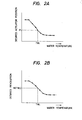
- Fig. 2A shows a content of the desired actuator position vs. water temperature map memory 111 and Fig. 2B shows a content of the desired revolution vs. water temperature map memory portion 121.
- Fig. 3A shows a content of the conversion map memory portion 113 for conversion between position deflection and drive time
- Fig. 3B shows a content of the drive time ocnversion map memory 123 for conversion between drive time and revolution deflection.
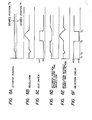
- Fig. 4A is a time chart of the actuator position to be maintained
- Fig. 4B is that of the engine revolution Ne under the same condition
- Figs. 4C, 4D and 4E are a state of the idle switch for determining whether or not the throttle valve 2 is to be in the idling condition, a vehicle speed signal indicative of a vehicle running and parking conditions and an operation mode selected by the selection circuit 130, respectively.
- the idle revolution is maintained by provisions of the lever 3 fixed on the throttle shaft of the throttle valve and the actuator 4 arranged in facing relation to the lever 3, as usual. That is, the idle revolution is maintained by regulating the position of the rod 5 of the actuator to push up the lever 3 to a predetermined position.
- the idle switch is in a closed state.
- the operating condition judging portion 132 judges it as an idle condition of the engine and causes the exchange switch 131 to be connected to the side of the revolution feedback control portion 120.
- the desired idle revolution number corresponding to the output of the water temperature sensor 8 is stored in the desired revolution map memory 121 of the revolution number feedback control portion 120 as mentioned with reference to Fig. 2B. Therefore, when a current water temperature is represented by T w i, the desired revolution number N(T w i) is derived from the stored map and supplied to the comparator 122.
- the comparator 122 compares the desired revolution number N(T w ⁇ ) with an actual revolution number N(ti) detected by the revolution number detector 7 and sends a resultant deflection of revolution number to the revolution deflection-drive time conversion map memory 123 which stores the drive time of the actuator 4 for which the revolution deflection can be compensated for by one drive operation, as shown in Fig. 3B.
- the drive time for a revolution deflection ANi is T ⁇ Ni and a voltage signal corresponding to a driving direction and the drive time is supplied to the selection circuit 130.
- the exchange switch 131 of the selection circuit 130 is connected to the revolution number feedback control portion 120 at this time, the voltage signal is transmitted through the drive circuit 150 to the actuator 4 to drive the latter for a time corresponding thereto. As a result, the rod 5 is moved to shift the throttle valve 2 through the lever 3 to thereby regulate the revolution toward the desired revolution number.
- the switch 145 of the average position deflection operation portion 140 is kept closed during the revolution feedback control (NFB) operation. Therefore, a first desired position derived from the desired actuator position map memory 111 is compared in the comparator 141 with an actual position of the actuator 4 a result of which is supplied to the average operation portion 142.
- the map memory 111 has the content basically corresponding to the content of the desired revolution map memory 121 and stores the desired actuator position for the water temperature as shown in Fig. 2A. When a current water temperature is T w i, the desired actuator position is P i which is supplied to the comparator 141.
- the average operation portion 142 averages the deflection over a time period of 30 seconds to 30 minutes and a resultant average deflection value is stored in the non-vo- latime memory element 143 and at the same time, added to the position of the desired actuator position by the adder 144, which is used as a second desired actuator position.
- Such averaging operation is necessary to absorb an error caused by the fact that, when the position feedback control is performed, there may be revolution deflection produced due to a possible difference between the actuator position detected by the detector 6 and an actual amount of intake air, the revolution number deflection being different from vehicle to vehicle, and to obtain the deflection not for a temporary load variation but for an average of engine load variations caused by engine warming-up operation and/or loosely connected clutch oepration and/or electric load variation.
- the time period for the averaging operation is set to a value from about 30 seconds to about 30 minutes as mentioned above.
- the non-volatile memory element 143 is connected directly to a battery of the engine, so that it holds a preceding average deflection value even after a key switch is turned off.
- a car is decided as a complete new car when an electric power is supplied to the non-volatile memory element 143 firstly and a predetermined initial position deflection value is set in the memory element 143.
- the predetermined initial position deflection value corresponds to friction loss of the new car which corresponds to a value for providing an increase of idle revolution number by 100 to 150 rpm, generally.
- the signal indicative of the second desired actuator position supplied from the adder 144 is compared in the comparator 112 of the position feedback control portion 110 with an actual position detected by the actuator position detector 6 and a resultant difference is supplied to the position deflection-drive time map memory 113 which contains the drive time of the actuator 4 for the position defleciton as shown in Fig. 3A.
- the drive time is given as T( A p, ) and a voltage signal corresponding to the drive time and the drive direction is supplied to the selection circuit 130.
- the exchange switch 131 of the selection circuit 130 is connected to the revolution feedback control portion 120 when the engine is in idling state. On the other hand, when the accelerator is pushed down and the idle switch is turned off thereby, the switch 131 is connected to the position feedback control portion 110.
- the exchange switch 131 selects the position feedback control (PFB).
- the switch 145 of the average position deflection operating portion 140 is turned off and the average position deflection stored during the NFB is added to the desired position to provide the second desired position upon which the PFB is performed.
- the PFB is still performed on the second desired position. Therefore, the engine stop problem and/or the operator's feeling of lack of deceleration is removed. Further, at a time instance t 4 after a time at which the car is stopped and the engine thereof becomes the idling condition, the NFB is performed and the average position defleciton operating portion 140 performs an averaging operation of the deflection between the desired position and an actual position.
- Fig. 5 shows another embodiment of the present invention which is substantially the same as the first embodiment shown in Fig. 1 except the position deflection operating portion 140.
- the position deflection operating portion 140 of the second embodiment includes, additionally, a short time deflection operating circuit 147, a non-volatile memory element 146, a switch 148 for selectively bypassing the average deflection operating circuit 144 and an adder 149.
- the operating condition judging portion 132 decides it as an idling condition and switches the exchange switch 131 onto the side of the revolution feedback control portion 120. Therefore, the desired revolution number from the revolution map memory 121 is supplied to the comparator 122. Subsequent operations are the same as those described with reference to the embodiment in Fig. 5.
- the switch 131 is switched to the position feedback control side and thus the PFB is performed.
- the switch 145 is turned off by the judging portion 132 and a learning operation of the average position deflection is terminated, so that the short time position deflection and the average position deflection stored in the memory elements 143 and 146 are added to each other by the adder 144 to provide a second desired actuator position signal which is sent to the comparator 112.
- the comparator 112 compares this signal with an actual position signal from the detector 6 and a difference therebetween is stored in the position deflection drive time conversion map memory 113.
- a drive time signal from the memory 113 is supplied through the selection circuit 130 to the drive 150 to control the actuator 4.
- the switch 148 is turned off during the vehicle is running to avoid the summation of the short time position deflection.
- Conditions under which the switch 148 is turned off may be the engine revolution above a predetermined value, e.g., 1000 rpm. In such case, it is possible to restrict the revolution variation of the engine in idle condition so long as the engine revolution is not more than 1000 rpm even if the vehicle is running.
- Fig. 7 shows a third embodiment of the present invention, which is the same as that shown in Fig. 5 except a provision of a first revolution judging portion 124 and a second revolution judging portion 160 which turns the switch 148 off when the actual engine revolution becomes higher than 1000 rpm.
- the first revolution judging portion 124 serves to compare the actual engine revolution from the revolution number detector with the desired revolution from the map memory 121 and provides an output when the latter is higher than the actual revolution.
- the selection circuit 132 comprises an AND gate 132a having inputs connected to the idle switch and the vehicle speed switch 9, respectively, and an OR gate 132b having inputs connected to an output of the first judging portion 124 and an output of the AND gate 132a.
- An output of the OR gate 132b is associated with the switch 131 to turn it on the side of the revolution feedback control portion 120 when it is "H".
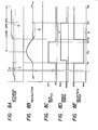
- Figs. 8A to 8E the vehicle is in a parking condition before a time instance t 21 in which the average deflection operating portion 147 averages the difference between the actual revolution and the desired revolution as shown by a letter a in Fig. 8A until the short time position defleciton b becomes zero.
- the switch 131 is switched on the side of the position feedback control portion 110 to perform the PFB as mentioned pervfously.
- the first revolution judging portion 124 provides trhe output signal by which the output of the OR gate 132b becomes "H" and thus the switch 131 is connected to the side of the revolution feedback control portion 120 regardless of the state of the idle switch and the vehicle running condition. Therefore, the actuator position is added by the load increment by which the engine revolution is immediately regulated to the desired value.
- chain lines b show curves in these figures when there is no revolution judging poriton 124 provided.
- the PFB contorl is performed since the vehicle is running at the time isntance t 24 and therefore the actuator position is unchanced so that the revolution is lowered by an amount corresponding to the load increment, this being continued until the time instance t 25 . Then, when the load increment is removed at t 25 , the revolution is stabilized at the predetermined value after a slight increase due to the NFB control performed.
- Figs. 9A to 9E are time charts of operation of the third embodiment when the vehicle is started with half-clutch condition. Assuming that the accelerator is actuated at a time instance t 31 and the idle switch is turned off and then that the clutch is half-connected at a time instance t 32 , the selection circuit 130 selects the revolution feedback control portion 120 when the engine revolution is lowered below the desired value, e.g., to 700 rpm. Thus, the actuator position is regulated toward the throttle open side to increase the revolution.
- the desired value e.g., to 700 rpm
- the control is switched to the PFB and the actuator position at t 33 becomes the value which is the sum of the average position deflection a and the short time position deflection b in Fig. 9A.
- the engine revolution may increase abnormally when the actuator position is corrected by the sum. This problem is solved by turning the switch 148 off by the second revolution judging portion 160 when the revolution at a time instance t 34 exceeds 1000 rpm so that the short time position deflection b is reset.
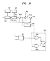
- Fig. 10 shows another embodiment of the present invention by which the NFB control is prohibited when the sum of the average position deflection and the short time position deflection obtained by the position defleciton operating portion 140 is not less than a predetermined value.
- the selection circuit 130 further comprises an AND gate 132c connected between the output of the first revolution judging portion 124 and the OR gate 132b in Fig. 7.
- the other input of the OR gate 132c is connected through an open degree judging portion 170 to a junction between adders 144a and 144b which constitute the adder 144.
- the open degree judging portion 170 serves to judge whether or not an output of the adder 144a is not more than a predetermined value.
- the adder 144b serves to add the output of the adder 144a to the output of the actuator position map memory 111.
- the NFB control is performed when the idle switch is turned on while the vehicle is parking as well as when the actual engine revolution is not more than the desired value.
- the learned value i.e., the sum of the short time position deflection and the average position deflection
- the open degree judging portion 170 provides a "H" output when the learned value is not more than the predetermined value and an "L" output when it is not less than the predetermined value. Therefore, when the learned value is not less than the predetermined value, the output of the AND gate 132c becomes "L" and the OR gate 132b prohibits the NFB control when the vehicle is not parking. This is because, when the learned value exceeds the predetermined value, there may be some engine abnormality and thus the NFB control is prevented.
- the actuator is controlled by correcting the desired position thereof with an average value of deflection between the actual position and the desired position. Therefore, the deceleration of vehicle can be performed without engine stop problem while providing an enough deceleration feeling to an operator.
Landscapes
- Engineering & Computer Science (AREA)
- Chemical & Material Sciences (AREA)
- Combustion & Propulsion (AREA)
- Mechanical Engineering (AREA)
- General Engineering & Computer Science (AREA)
- Electrical Control Of Air Or Fuel Supplied To Internal-Combustion Engine (AREA)
- Control Of Vehicle Engines Or Engines For Specific Uses (AREA)
- Combined Controls Of Internal Combustion Engines (AREA)
Applications Claiming Priority (6)
| Application Number | Priority Date | Filing Date | Title |
|---|---|---|---|
| JP150406/86 | 1986-06-26 | ||
| JP61150405A JPS635135A (ja) | 1986-06-26 | 1986-06-26 | 内燃機関のアイドル回転数制御装置 |
| JP15040686A JPS635136A (ja) | 1986-06-26 | 1986-06-26 | 内燃機関のアイドル回転数制御装置 |
| JP150404/86 | 1986-06-26 | ||
| JP150405/86 | 1986-06-26 | ||
| JP15040486A JPS635134A (ja) | 1986-06-26 | 1986-06-26 | 内燃機関のアイドル回転数制御装置 |
Publications (3)
| Publication Number | Publication Date |
|---|---|
| EP0251723A2 true EP0251723A2 (de) | 1988-01-07 |
| EP0251723A3 EP0251723A3 (en) | 1988-12-14 |
| EP0251723B1 EP0251723B1 (de) | 1991-01-09 |
Family
ID=27319916
Family Applications (1)
| Application Number | Title | Priority Date | Filing Date |
|---|---|---|---|
| EP87305693A Expired - Lifetime EP0251723B1 (de) | 1986-06-26 | 1987-06-25 | Leerlaufdrehzahlsteuerungsgerät für Brennkraftmaschinen |
Country Status (5)
| Country | Link |
|---|---|
| US (1) | US4790276A (de) |
| EP (1) | EP0251723B1 (de) |
| KR (1) | KR900006088B1 (de) |
| AU (1) | AU590092B2 (de) |
| DE (1) | DE3767229D1 (de) |
Cited By (2)
| Publication number | Priority date | Publication date | Assignee | Title |
|---|---|---|---|---|
| WO1990007052A1 (de) * | 1988-12-14 | 1990-06-28 | Robert Bosch Gmbh | Verfahren und vorrichtung zum adaptieren der kennlinie eines leerlaufstellers |
| WO1991000957A1 (de) * | 1989-07-07 | 1991-01-24 | Robert Bosch Gmbh | System zur steuerung einer brennkraftmaschine |
Families Citing this family (5)
| Publication number | Priority date | Publication date | Assignee | Title |
|---|---|---|---|---|
| DE3733623A1 (de) * | 1987-10-05 | 1989-04-13 | Bosch Gmbh Robert | Einrichtung zur einstellung einer betriebskenngroesse einer brennkraftmaschine |
| US5040507A (en) * | 1990-03-07 | 1991-08-20 | Cummins Engine Company, Inc. | Method and device for variable idle speed control of an internal combustion engine |
| JP3224727B2 (ja) * | 1995-12-19 | 2001-11-05 | 関西ペイント株式会社 | 塗料供給方法及び自動車ボディの上塗塗装方法 |
| DE19748128A1 (de) * | 1997-10-31 | 1999-05-06 | Bosch Gmbh Robert | Verfahren und Vorrichtung zur Steuerung eines Stellelements einer Antriebseinheit |
| KR100422615B1 (ko) * | 1997-12-16 | 2004-06-16 | 현대자동차주식회사 | 티씨에스의 스로틀 개도 제어장치 및 그 방법 |
Family Cites Families (2)
| Publication number | Priority date | Publication date | Assignee | Title |
|---|---|---|---|---|
| JPS5932645A (ja) * | 1982-08-16 | 1984-02-22 | Mazda Motor Corp | エンジンのアイドル回転制御装置 |
| US4580535A (en) * | 1985-06-03 | 1986-04-08 | Mitsubishi Jidosha Kogyo Kabushiki Kaisha | Engine idling speed controlling system |
-
1987
- 1987-05-29 KR KR1019870005429A patent/KR900006088B1/ko not_active Expired
- 1987-06-25 EP EP87305693A patent/EP0251723B1/de not_active Expired - Lifetime
- 1987-06-25 AU AU74708/87A patent/AU590092B2/en not_active Expired
- 1987-06-25 DE DE8787305693T patent/DE3767229D1/de not_active Expired - Lifetime
- 1987-06-26 US US07/066,448 patent/US4790276A/en not_active Expired - Lifetime
Cited By (2)
| Publication number | Priority date | Publication date | Assignee | Title |
|---|---|---|---|---|
| WO1990007052A1 (de) * | 1988-12-14 | 1990-06-28 | Robert Bosch Gmbh | Verfahren und vorrichtung zum adaptieren der kennlinie eines leerlaufstellers |
| WO1991000957A1 (de) * | 1989-07-07 | 1991-01-24 | Robert Bosch Gmbh | System zur steuerung einer brennkraftmaschine |
Also Published As
| Publication number | Publication date |
|---|---|
| AU7470887A (en) | 1988-01-07 |
| KR880000682A (ko) | 1988-03-28 |
| EP0251723A3 (en) | 1988-12-14 |
| KR900006088B1 (ko) | 1990-08-22 |
| DE3767229D1 (de) | 1991-02-14 |
| US4790276A (en) | 1988-12-13 |
| AU590092B2 (en) | 1989-10-26 |
| EP0251723B1 (de) | 1991-01-09 |
Similar Documents
| Publication | Publication Date | Title |
|---|---|---|
| US4698762A (en) | Cruise control apparatus for vehicles | |
| US5307777A (en) | Throttle opening control system for automotive engine | |
| JPH071994A (ja) | 車両の駆動出力を制御する方法と装置 | |
| JPH06123242A (ja) | スロットルバルブ制御装置 | |
| JPS6328222B2 (de) | ||
| US4790276A (en) | Idling revolution control device for internal combustion engine | |
| US5415142A (en) | Control method and apparatus for internal combustion engine | |
| KR0137222B1 (ko) | 공기/연료 혼합물의 람다값 조정 방법 및 시스템 | |
| JPS6328221B2 (de) | ||
| US4993383A (en) | Controller unit | |
| US5396869A (en) | Fuel supply control device of internal-combustion engine | |
| JPH0346200Y2 (de) | ||
| US6915202B2 (en) | Method and arrangement for controlling the drive unit of a vehicle | |
| EP0249340B1 (de) | Vorrichtung zur Steuerung des Leerlaufbetriebs einer Brennkraftmaschine | |
| JP4354093B2 (ja) | 自動変速機搭載車両のエンジン制御方法 | |
| GB2270352A (en) | Engine and transmission control apparatus reduces load signal to transmission control for small accelerator pedal movements | |
| JP3844911B2 (ja) | 内燃機関のスロットル制御装置 | |
| JPH0313541Y2 (de) | ||
| JP3562938B2 (ja) | 内燃機関のスロットル弁制御装置 | |
| JP3772921B2 (ja) | 内燃機関のアイドル回転数制御装置 | |
| JPH11200936A (ja) | 駆動ユニットの設定要素の制御方法及び装置 | |
| JP3159102B2 (ja) | 内燃機関の電子スロットル制御装置 | |
| JP3876358B2 (ja) | アクセルペダルセンサの全閉出力学習装置 | |
| JP2842123B2 (ja) | 電子制御燃料噴射ポンプ装置付きディーゼル機関 | |
| JP3731443B2 (ja) | 内燃機関のスロットル制御装置 |
Legal Events
| Date | Code | Title | Description |
|---|---|---|---|
| PUAI | Public reference made under article 153(3) epc to a published international application that has entered the european phase |
Free format text: ORIGINAL CODE: 0009012 |
|
| AK | Designated contracting states |
Kind code of ref document: A2 Designated state(s): DE FR GB |
|
| PUAL | Search report despatched |
Free format text: ORIGINAL CODE: 0009013 |
|
| AK | Designated contracting states |
Kind code of ref document: A3 Designated state(s): DE FR GB |
|
| 17P | Request for examination filed |
Effective date: 19890605 |
|
| 17Q | First examination report despatched |
Effective date: 19900112 |
|
| GRAA | (expected) grant |
Free format text: ORIGINAL CODE: 0009210 |
|
| AK | Designated contracting states |
Kind code of ref document: B1 Designated state(s): DE FR GB |
|
| REF | Corresponds to: |
Ref document number: 3767229 Country of ref document: DE Date of ref document: 19910214 |
|
| ET | Fr: translation filed | ||
| PLBE | No opposition filed within time limit |
Free format text: ORIGINAL CODE: 0009261 |
|
| STAA | Information on the status of an ep patent application or granted ep patent |
Free format text: STATUS: NO OPPOSITION FILED WITHIN TIME LIMIT |
|
| 26N | No opposition filed | ||
| REG | Reference to a national code |
Ref country code: GB Ref legal event code: IF02 |
|
| PGFP | Annual fee paid to national office [announced via postgrant information from national office to epo] |
Ref country code: FR Payment date: 20060608 Year of fee payment: 20 |
|
| PGFP | Annual fee paid to national office [announced via postgrant information from national office to epo] |
Ref country code: GB Payment date: 20060621 Year of fee payment: 20 |
|
| PGFP | Annual fee paid to national office [announced via postgrant information from national office to epo] |
Ref country code: DE Payment date: 20060622 Year of fee payment: 20 |
|
| REG | Reference to a national code |
Ref country code: GB Ref legal event code: PE20 |
|
| PG25 | Lapsed in a contracting state [announced via postgrant information from national office to epo] |
Ref country code: GB Free format text: LAPSE BECAUSE OF EXPIRATION OF PROTECTION Effective date: 20070624 |