EP0251756A2 - Poulie à vitesse variable - Google Patents
Poulie à vitesse variableInfo
- Publication number
- EP0251756A2 EP0251756A2 EP87305758A EP87305758A EP0251756A2 EP 0251756 A2 EP0251756 A2 EP 0251756A2 EP 87305758 A EP87305758 A EP 87305758A EP 87305758 A EP87305758 A EP 87305758A EP 0251756 A2 EP0251756 A2 EP 0251756A2
- Authority
- EP
- European Patent Office
- Prior art keywords
- sheave half
- pulley
- variable speed
- shaft
- sheave
- Prior art date
- Legal status (The legal status is an assumption and is not a legal conclusion. Google has not performed a legal analysis and makes no representation as to the accuracy of the status listed.)
- Granted
Links
Images
Classifications
-
- F—MECHANICAL ENGINEERING; LIGHTING; HEATING; WEAPONS; BLASTING
- F16—ENGINEERING ELEMENTS AND UNITS; GENERAL MEASURES FOR PRODUCING AND MAINTAINING EFFECTIVE FUNCTIONING OF MACHINES OR INSTALLATIONS; THERMAL INSULATION IN GENERAL
- F16H—GEARING
- F16H55/00—Elements with teeth or friction surfaces for conveying motion; Worms, pulleys or sheaves for gearing mechanisms
- F16H55/32—Friction members
- F16H55/36—Pulleys
- F16H55/49—Features essential to V-belts pulleys
-
- F—MECHANICAL ENGINEERING; LIGHTING; HEATING; WEAPONS; BLASTING
- F16—ENGINEERING ELEMENTS AND UNITS; GENERAL MEASURES FOR PRODUCING AND MAINTAINING EFFECTIVE FUNCTIONING OF MACHINES OR INSTALLATIONS; THERMAL INSULATION IN GENERAL
- F16H—GEARING
- F16H61/00—Control functions within control units of change-speed- or reversing-gearings for conveying rotary motion ; Control of exclusively fluid gearing, friction gearing, gearings with endless flexible members or other particular types of gearing
- F16H61/66—Control functions within control units of change-speed- or reversing-gearings for conveying rotary motion ; Control of exclusively fluid gearing, friction gearing, gearings with endless flexible members or other particular types of gearing specially adapted for continuously variable gearings
- F16H61/662—Control functions within control units of change-speed- or reversing-gearings for conveying rotary motion ; Control of exclusively fluid gearing, friction gearing, gearings with endless flexible members or other particular types of gearing specially adapted for continuously variable gearings with endless flexible members
- F16H61/66231—Control functions within control units of change-speed- or reversing-gearings for conveying rotary motion ; Control of exclusively fluid gearing, friction gearing, gearings with endless flexible members or other particular types of gearing specially adapted for continuously variable gearings with endless flexible members controlling shifting exclusively as a function of speed
- F16H61/66245—Control functions within control units of change-speed- or reversing-gearings for conveying rotary motion ; Control of exclusively fluid gearing, friction gearing, gearings with endless flexible members or other particular types of gearing specially adapted for continuously variable gearings with endless flexible members controlling shifting exclusively as a function of speed using purely mechanical sensing or control means
-
- F—MECHANICAL ENGINEERING; LIGHTING; HEATING; WEAPONS; BLASTING
- F16—ENGINEERING ELEMENTS AND UNITS; GENERAL MEASURES FOR PRODUCING AND MAINTAINING EFFECTIVE FUNCTIONING OF MACHINES OR INSTALLATIONS; THERMAL INSULATION IN GENERAL
- F16H—GEARING
- F16H55/00—Elements with teeth or friction surfaces for conveying motion; Worms, pulleys or sheaves for gearing mechanisms
- F16H55/32—Friction members
- F16H55/52—Pulleys or friction discs of adjustable construction
- F16H55/56—Pulleys or friction discs of adjustable construction of which the bearing parts are relatively axially adjustable
- F16H55/563—Pulleys or friction discs of adjustable construction of which the bearing parts are relatively axially adjustable actuated by centrifugal masses
-
- F—MECHANICAL ENGINEERING; LIGHTING; HEATING; WEAPONS; BLASTING
- F16—ENGINEERING ELEMENTS AND UNITS; GENERAL MEASURES FOR PRODUCING AND MAINTAINING EFFECTIVE FUNCTIONING OF MACHINES OR INSTALLATIONS; THERMAL INSULATION IN GENERAL
- F16H—GEARING
- F16H9/00—Gearings for conveying rotary motion with variable gear ratio, or for reversing rotary motion, by endless flexible members
- F16H9/02—Gearings for conveying rotary motion with variable gear ratio, or for reversing rotary motion, by endless flexible members without members having orbital motion
- F16H9/24—Gearings for conveying rotary motion with variable gear ratio, or for reversing rotary motion, by endless flexible members without members having orbital motion using chains or toothed belts, belts in the form of links; Chains or belts specially adapted to such gearing
Definitions
- This invention relates to power transmission belt pulleys and in particular to variable speed power transmission belt pulleys.
- a movable pulley sheave half is urged toward a fixed sheave half by a spring.
- the belt overcomes the biasing force of the spring, permitting the movable sheave to move away from the fixed sheave and thereby reducing the effective diameter of the pulley, and thereby automatically varying the speed of the pulley driven by the belt.
- the spherical bodies tend to move circumferentially of the annular space, and eventually may be disposed entirely circumferentially thereof.
- the spherical bodies it has been found that there is a tendency for the spherical bodies to nonuniformly distribute themselves as a result of friction. Undesirable bridging occurs so that even after a substantial period of running of the pulley, vibration and noise continues.
- the pulley structure includes a plurality of spherical force transmitting elements 5 which collect in a lower portion of the space 6 in which they are retained when the pulley is in a standstill position, as shown in Figure 10.
- the centrifugal forces developed in the elements 5 tend to urge them toward an outer disposition, as shown in Figure 9.
- the elements 5 do not uniformly redistribute themselves circumferentially about the outer portion of the space 6 and vibration and noise occur not only during speedup, but also during subsequent changes, as well as during steady state operation of the pulley.
- the pulley structure of Japanese Patent 42-12433 has not proven fully satisfactory in use.
- the biasing spring comprises a helical spring having one end connected fixedly to the shaft, and the opposite end connected fixedly to the movable sheave.
- the spring not only biases the movable sheave half toward the opposite sheave half, but also permits some angular displacement of the movable sheave half about the axis of the shaft so as to accommodate shock forces and the like generated in the operation of the belt drive.
- the present invention comprehends an improved variable speed pulley structure utilizing force applying means having a variable extension parallel to the shaft axis proportional to the centrifugal force acting thereon as a result of the speed of rotation of the pulley, and wherein rearrangement means are provided for varying the arrangement of the force applying means as an incident of relative movement between the first and second sheave angularly about the axis of rotation.
- the rearrangement means utilizes a spring providing a change in the relative rotational positions of the surfaces defining the opposite sides of a space in which the force applying means is disposed.
- the force applying means is rearranged as a result of force transfer thereto from the opposite surfaces as they move relative to each other.
- the force applying means comprises a plurality of small spherical elements, and the rearrangement means acts to uniformly distribute the elements throughout the annular space in which they are re ceived between the thusly relatively movable opposite surfaces defining the space.
- lubricating means may be provided for reducing friction between the respective elements.
- the elements are provided with a low friction coating.
- lubricant may be provided in the space.
- the rearrangement means is disposed radially inwardly of the force applying means, and in a second form, the rearrangement means is disposed axially outwardly thereof.
- the spherical elements are preferably of small diameter and, more specifically, in the illustrated embodiment, have a diameter in the range of approximately 1 to 6 mm. Improved functioning has been found to result from the provision of the spherical elements having a diameter in the range of approximately 2 to 4 mm.
- All of the rounded elements may have a similar rounded shape.
- the rounded elements may comprise a mixture of elements having different rounded shapes.
- variable speed pulley of the present invention is extremely simple and economical of construction, while yet providing the highly desirable features discussed above.
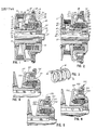
- variable speed pulley 10 is shown to comprise a first sheave half 11 and a second sheave half 12 defining confronting faces 13 and 14, respectively, defining a belt receiving groove 15.
- Sheave half 11 is fixedly associated with a power drive shaft 16 by means of a sleeve 17 locked to the shaft 16 by a key 18 received in a keyway 19 in the shaft.
- a plurality of bolts 20 extend through an annular flange 21 on the sleeve and are threaded into the sheave half 11, as shown in Figure 1.
- Sheave half 12 comprises a movable sheave half coaxially mounted to a cylindrical outer surface 22 of the sleeve 17 on annular sleeve bearings 23, which illustratively may be formed of copper alloy, polytetrafluorethylene, oil-containing metal, etc., whereby sheave half 12 is both axially and rotatively readily movable on the sleeve.
- An annular stopper 24 is fixedly secured to the sleeve 17 by a plurality of bolts 25 and, thus, is fixed against rotation and axial movement relative to the shaft 16.
- the stopper includes a radially outer, longitudinally extending annular portion 26 and an outturned distal flange 27.
- Sheave half 12 defines a radially outer annular wall 28 provided with a distal, radially outturned annular flange 29.
- An annular closure wall 30 is fixedly mounted to flange 29 by a plurality of bolts 31.
- a space, or chamber, 32 is formed between an axially outer facing surface 33 of flange 27, and an axially inwardly facing surface 34 of closure wall 30.
- Force applying means in the form of a plurality of small rounded elements 35 are provided in space 32, which is thusly effectively enclosed by stopper wall 26, distal flange 27, extension wall 28 of sheave half 12, and closure wall 30.
- Movable sheave half 12 is biased toward fixed sheave half 11 by a helical spring 36 extending concentrically of the axis 37 of shaft 16. As shown in Figure 3, the distal end portions of springs 36 are provided with apertures 38 and 39, respectively.
- spring aperture 38 receives the axially projecting end 40 of a retaining pin 41 secured in a mounting portion 42 of sheave half 12.
- the opposite spring end aperture 39 receives a projecting portion 43 of a retaining pin 44 mounted in the stopper 24.
- spring 36 is captured under compression between the sheave portion 42 and stopper 24, with the opposite ends of the spring connected thereto to effect alternative winding and unwinding of the spring corresponding to opposite rotational displacement of the movable sheave half 12 on sleeve 17, as during driving operation of the pulley.
- the invention further comprehends the provision of means for reducing friction between the rounded elements 35.
- fluid lubricant may be provided in the spaces in which the spring 36 and rounded elements 35 are disposed and maintained against leakage therefrom by a pair of O-rings 45 and 46 in movable sheave half mounting portion 42 and closure wall 30, respectively.
- O-ring 45 seals sheave half 12 to the sleeve 17
- O-ring 46 seals closure wall 30 to the annular portion 26 of the stopper, as illustrated in Figure 2.
- the force applying means are illustrated in the drawing as comprising relatively small diameter, rounded, or spherical, elements.
- the illustrated elements may have a diameter in the range of approximately 1 to 6 mm., and preferably, in the range of approximately 2 to 4 mm.
- the force applying means may be particulate, such as powder and the like.
- the force applying elements 35 may be formed of conventional steel, copper, stainless steel, tungsten, etc.
- the elements may be coated, such as with a synthetic resin, metal powder embedded in resin, or other friction reducing means. Any suitable fluid lubricant may be utilized for reducing the friction between the elements 35, as discussed above.
- the elements have a regular spherical shape. Elements deviating from the true spherical shape may be utilized, and have been found to further reduce bridging and uniformity of distribution.
- the invention comprehends that all of the elements may have the same shape and size as well as having different shapes and sizes.
- the space 32 has a generally triangular configuration in the minimum volume arrangement, and a generally trapezoidal configuration when acting to increase the spacing between the movable sheave half 12 and fixed sheave half 11.
- the confronting surfaces 33 and 34 defining the axially opposite ends of space 32 are equally oppositely angularly inclined to the shaft axis 37 in pulley 10.
- the invention comprehends other arrangements, such as that shown in Figure 4 wherein the pulley structure general strictlyly designated 110 includes a closure wall 130 defining a radially planar surface 134 confronting the inclined surface 133 on the flange 127.
- variable speed pulley generally designated 210 is provided with a closure wall 230 defining a concave surface 234, and flange 227 defines a complementary concave surface 233.
- variable speed pulley 310 is illustrated in Figure 6 to include a closure wall 330 defining a convex inner surface 334 and flange 327 defines a complementary convex surface 333 defining the axially opposite surfaces of the space 332.
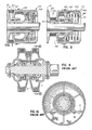
- a further modified form of pulley structure generally designated 410 comprises a pulley structure wherein the spring 436 of the rearrangement means is disposed axially outwardly of the force applying elements 435.
- the movable pulley sheave half 412 is rotatably mounted on the sleeve 417 and has an annular spring retainer 447 secured to its distal end by a set screw 448.
- Spring 436 biases the movable sheave half 412 to the right, as seen in Figure 8, as a result of its compression between retainer 447 and wall 430 mounted to the sleeve 417.
- groove 414 of the pulley is urged to its widest configuration whereby the power transmission belt B is disposed in a radially inner portion of the groove.
- the force applying elements 435 are urged by centrifugal force radially outwardly toward the position of Figure 7, thereby urging the movable sheave half 412 toward fixed sheave half 411 against the biasing action of spring 436.
- the drive belt B is disposed in the radially outer portion of the pulley groove 414, whereby the pulley effectively defines its maximum diameter.
- the pulley structure 410 functions similarly to the pulley structures of the embodiments of Figures 1-6 except that an increase in the speed of the pulley in pulley structure 410 causes a narrowing of the belt groove, whereas in the embodiments of pulleys 10, 110, 210, and 310, an increase in the speed effects a widening of the pulley groove.
- a smooth redistribution of the force applying elements is effected as a result of relative movement between the surfaces defining opposite sides of the space in which the force applying elements are retained.
- spring 436 which has its opposite ends connected to spring retainer 447 by a pin 441 and closure wall 430 by a pin 444 permits limited rotative displacement of sheave half 412 relative to sheave half 411 as a result of a change in the force applied by the belt B to the sheave halves as during driving operation of the system.
- the pulley structures of the present invention provide an improved control of the variable width pulley groove thereof.
- the force applying means is caused to have a smooth uniform distribution, avoiding vibration and noise as a result of its cooperation with the shock absorbing spring means.
Landscapes
- Engineering & Computer Science (AREA)
- General Engineering & Computer Science (AREA)
- Mechanical Engineering (AREA)
- Transmissions By Endless Flexible Members (AREA)
- Pulleys (AREA)
- Valve Device For Special Equipments (AREA)
Priority Applications (1)
| Application Number | Priority Date | Filing Date | Title |
|---|---|---|---|
| AT87305758T ATE50035T1 (de) | 1986-06-30 | 1987-06-29 | Riemenscheibe fuer veraenderbare geschwindigkeit. |
Applications Claiming Priority (2)
| Application Number | Priority Date | Filing Date | Title |
|---|---|---|---|
| JP153666/86 | 1986-06-30 | ||
| JP61153666A JPS639762A (ja) | 1986-06-30 | 1986-06-30 | 遠心推力式変速プ−リ |
Publications (3)
| Publication Number | Publication Date |
|---|---|
| EP0251756A2 true EP0251756A2 (fr) | 1988-01-07 |
| EP0251756A3 EP0251756A3 (en) | 1988-07-06 |
| EP0251756B1 EP0251756B1 (fr) | 1990-01-31 |
Family
ID=15567520
Family Applications (1)
| Application Number | Title | Priority Date | Filing Date |
|---|---|---|---|
| EP87305758A Expired - Lifetime EP0251756B1 (fr) | 1986-06-30 | 1987-06-29 | Poulie à vitesse variable |
Country Status (8)
| Country | Link |
|---|---|
| US (2) | US4789378A (fr) |
| EP (1) | EP0251756B1 (fr) |
| JP (1) | JPS639762A (fr) |
| KR (1) | KR910001905B1 (fr) |
| AT (1) | ATE50035T1 (fr) |
| CA (1) | CA1286526C (fr) |
| DE (1) | DE3761589D1 (fr) |
| MX (1) | MX171505B (fr) |
Cited By (4)
| Publication number | Priority date | Publication date | Assignee | Title |
|---|---|---|---|---|
| US4902265A (en) * | 1987-09-05 | 1990-02-20 | Mitsuboshi Belting Ltd. | Variable speed pulley |
| US4976657A (en) * | 1989-07-10 | 1990-12-11 | Mitsuboshi Belting Ltd. | Belt-type stepless speed shifting apparatus |
| WO1993006388A1 (fr) * | 1991-09-27 | 1993-04-01 | Ibc Powerbloc Canada | Poulie menante d'une transmission a courroie a vitesse variable equipee de masselottes dentees |
| DE10052652A1 (de) * | 2000-10-24 | 2003-02-13 | Volkswagen Ag | Stufenlos verstellbares Getriebe |
Families Citing this family (6)
| Publication number | Priority date | Publication date | Assignee | Title |
|---|---|---|---|---|
| NL8900674A (nl) * | 1989-03-20 | 1990-10-16 | Doornes Transmissie Bv | Poelie. |
| JPH0520004Y2 (fr) * | 1989-03-31 | 1993-05-26 | ||
| US5407394A (en) * | 1993-05-05 | 1995-04-18 | Borg-Warner Automotive, Inc. | Guide for an adjustable pulley in a continuously variable transmission |
| US7765039B1 (en) | 1994-02-15 | 2010-07-27 | Hagenbuch Leroy G | Apparatus for tracking and recording vital signs and task-related information of a vehicle to identify operating patterns |
| US6546363B1 (en) * | 1994-02-15 | 2003-04-08 | Leroy G. Hagenbuch | Apparatus for tracking and recording vital signs and task-related information of a vehicle to identify operating patterns |
| JP4246039B2 (ja) * | 2003-11-18 | 2009-04-02 | 日立建機株式会社 | 建設機械の稼働情報管理装置 |
Family Cites Families (8)
| Publication number | Priority date | Publication date | Assignee | Title |
|---|---|---|---|---|
| US2851894A (en) * | 1955-07-11 | 1958-09-16 | Gen Motors Corp | Variable diameter pulley |
| US2986043A (en) * | 1956-12-05 | 1961-05-30 | Motobecane Ateliers | Automatic variable-speed and clutch units |
| GB1426351A (en) * | 1973-02-08 | 1976-02-25 | Cam Gears Ltd | Belt drive systems |
| JPS516815A (ja) * | 1974-07-09 | 1976-01-20 | Nippon Musical Instruments Mfg | Sekishutsukokagatakaisakusei ni kigokin |
| JP2680482B2 (ja) * | 1990-06-25 | 1997-11-19 | 株式会社東芝 | 半導体基板、半導体基板と半導体装置の製造方法、並びに半導体基板の検査・評価方法 |
| JPS5740150A (en) * | 1980-08-22 | 1982-03-05 | Nippon Denso Co Ltd | Power transmission device |
| US4621038A (en) * | 1985-06-24 | 1986-11-04 | Xerox Corporation | Photoconductive imaging members with novel symmetrical fluorinated squaraine compounds |
| JPH0547064A (ja) * | 1991-08-08 | 1993-02-26 | Hitachi Ltd | ビデオテープレコーダの自動選曲モード切換え制御方式 |
-
1986
- 1986-06-30 JP JP61153666A patent/JPS639762A/ja active Pending
-
1987
- 1987-06-25 CA CA000540625A patent/CA1286526C/fr not_active Expired - Fee Related
- 1987-06-26 KR KR1019870006502A patent/KR910001905B1/ko not_active Expired
- 1987-06-29 AT AT87305758T patent/ATE50035T1/de not_active IP Right Cessation
- 1987-06-29 EP EP87305758A patent/EP0251756B1/fr not_active Expired - Lifetime
- 1987-06-29 DE DE8787305758T patent/DE3761589D1/de not_active Expired - Fee Related
- 1987-06-29 US US07/067,691 patent/US4789378A/en not_active Expired - Fee Related
- 1987-06-30 MX MX007151A patent/MX171505B/es unknown
-
1988
- 1988-08-04 US US07/228,189 patent/US4838835A/en not_active Expired - Fee Related
Cited By (6)
| Publication number | Priority date | Publication date | Assignee | Title |
|---|---|---|---|---|
| US4902265A (en) * | 1987-09-05 | 1990-02-20 | Mitsuboshi Belting Ltd. | Variable speed pulley |
| US4976657A (en) * | 1989-07-10 | 1990-12-11 | Mitsuboshi Belting Ltd. | Belt-type stepless speed shifting apparatus |
| WO1993006388A1 (fr) * | 1991-09-27 | 1993-04-01 | Ibc Powerbloc Canada | Poulie menante d'une transmission a courroie a vitesse variable equipee de masselottes dentees |
| FR2681928A1 (fr) * | 1991-09-27 | 1993-04-02 | Powerbloc Ibc Canada Inc | Poulie menante d'une transmission a courroie a vitesse variable equipee de masselottes dentees. |
| US5514040A (en) * | 1991-09-27 | 1996-05-07 | Powerbloc Ibc Canada Inc. | Variable-speed belt drive having toothed flyweights |
| DE10052652A1 (de) * | 2000-10-24 | 2003-02-13 | Volkswagen Ag | Stufenlos verstellbares Getriebe |
Also Published As
| Publication number | Publication date |
|---|---|
| US4838835A (en) | 1989-06-13 |
| CA1286526C (fr) | 1991-07-23 |
| ATE50035T1 (de) | 1990-02-15 |
| EP0251756A3 (en) | 1988-07-06 |
| EP0251756B1 (fr) | 1990-01-31 |
| KR910001905B1 (ko) | 1991-03-30 |
| MX171505B (es) | 1993-11-03 |
| DE3761589D1 (de) | 1990-03-08 |
| JPS639762A (ja) | 1988-01-16 |
| KR880000716A (ko) | 1988-03-29 |
| US4789378A (en) | 1988-12-06 |
Similar Documents
| Publication | Publication Date | Title |
|---|---|---|
| US4360353A (en) | Power transmission system | |
| EP0158158B1 (fr) | Unité d'entraînement pour un dispositif auxiliaire, entraînée par un moteur | |
| EP0251756A2 (fr) | Poulie à vitesse variable | |
| US6004239A (en) | Friction type continuously variable speed changing mechanism | |
| EP0884504B1 (fr) | Poulie a diametre variable | |
| US6270436B1 (en) | Continuously variable transmission | |
| SK140194A3 (en) | An unbalance compensating method and apparatus | |
| CZ20021739A3 (cs) | Plynule měnitelná převodová řemenice | |
| US4380444A (en) | Variable ratio belt drive | |
| US5052981A (en) | Variable diameter pulley with centrifugal weights | |
| US6017285A (en) | Variable diameter pulley | |
| KR20070087131A (ko) | 자기-조정 가능한 견인 유성 롤러 전동 장치 | |
| EP1301736B1 (fr) | Coupleur cvt a couronnes d'entrainement de courroie | |
| US4976657A (en) | Belt-type stepless speed shifting apparatus | |
| DE4439993C2 (de) | Stufenloses Getriebe | |
| US4567789A (en) | Method and apparatus for changing speed using a differential band | |
| US4902265A (en) | Variable speed pulley | |
| US4557705A (en) | Variable ratio drive | |
| US4743221A (en) | Centrifugal clutch belt tightening assembly | |
| JPH04121566U (ja) | 変速プーリ | |
| DE3871831T2 (de) | Hilfsantrieb. | |
| JPS5962770A (ja) | Vベルト無段変速機 | |
| RU2112900C1 (ru) | Фрикционный реверсивный вариатор | |
| SU1622668A1 (ru) | Опора | |
| JPS6018646A (ja) | 速度調整装置 |
Legal Events
| Date | Code | Title | Description |
|---|---|---|---|
| PUAI | Public reference made under article 153(3) epc to a published international application that has entered the european phase |
Free format text: ORIGINAL CODE: 0009012 |
|
| 17P | Request for examination filed |
Effective date: 19870714 |
|
| AK | Designated contracting states |
Kind code of ref document: A2 Designated state(s): AT DE FR IT |
|
| PUAL | Search report despatched |
Free format text: ORIGINAL CODE: 0009013 |
|
| AK | Designated contracting states |
Kind code of ref document: A3 Designated state(s): AT DE FR IT |
|
| 17Q | First examination report despatched |
Effective date: 19890317 |
|
| GRAA | (expected) grant |
Free format text: ORIGINAL CODE: 0009210 |
|
| AK | Designated contracting states |
Kind code of ref document: B1 Designated state(s): AT DE FR IT |
|
| REF | Corresponds to: |
Ref document number: 50035 Country of ref document: AT Date of ref document: 19900215 Kind code of ref document: T |
|
| ITF | It: translation for a ep patent filed | ||
| REF | Corresponds to: |
Ref document number: 3761589 Country of ref document: DE Date of ref document: 19900308 |
|
| ET | Fr: translation filed | ||
| PLBE | No opposition filed within time limit |
Free format text: ORIGINAL CODE: 0009261 |
|
| STAA | Information on the status of an ep patent application or granted ep patent |
Free format text: STATUS: NO OPPOSITION FILED WITHIN TIME LIMIT |
|
| 26N | No opposition filed | ||
| PGFP | Annual fee paid to national office [announced via postgrant information from national office to epo] |
Ref country code: FR Payment date: 19920515 Year of fee payment: 6 |
|
| PGFP | Annual fee paid to national office [announced via postgrant information from national office to epo] |
Ref country code: AT Payment date: 19920519 Year of fee payment: 6 |
|
| PGFP | Annual fee paid to national office [announced via postgrant information from national office to epo] |
Ref country code: DE Payment date: 19930525 Year of fee payment: 7 |
|
| PG25 | Lapsed in a contracting state [announced via postgrant information from national office to epo] |
Ref country code: AT Effective date: 19930629 |
|
| PG25 | Lapsed in a contracting state [announced via postgrant information from national office to epo] |
Ref country code: FR Effective date: 19940228 |
|
| REG | Reference to a national code |
Ref country code: FR Ref legal event code: ST |
|
| PG25 | Lapsed in a contracting state [announced via postgrant information from national office to epo] |
Ref country code: DE Effective date: 19950301 |
|
| PG25 | Lapsed in a contracting state [announced via postgrant information from national office to epo] |
Ref country code: IT Free format text: LAPSE BECAUSE OF NON-PAYMENT OF DUE FEES;WARNING: LAPSES OF ITALIAN PATENTS WITH EFFECTIVE DATE BEFORE 2007 MAY HAVE OCCURRED AT ANY TIME BEFORE 2007. THE CORRECT EFFECTIVE DATE MAY BE DIFFERENT FROM THE ONE RECORDED. Effective date: 20050629 |