EP0251808A2 - Satelliten-Lageregelung - Google Patents
Satelliten-Lageregelung Download PDFInfo
- Publication number
- EP0251808A2 EP0251808A2 EP87305898A EP87305898A EP0251808A2 EP 0251808 A2 EP0251808 A2 EP 0251808A2 EP 87305898 A EP87305898 A EP 87305898A EP 87305898 A EP87305898 A EP 87305898A EP 0251808 A2 EP0251808 A2 EP 0251808A2
- Authority
- EP
- European Patent Office
- Prior art keywords
- satellite
- attitude
- thrusters
- actuators
- signals
- Prior art date
- Legal status (The legal status is an assumption and is not a legal conclusion. Google has not performed a legal analysis and makes no representation as to the accuracy of the status listed.)
- Withdrawn
Links
Images
Classifications
-
- B—PERFORMING OPERATIONS; TRANSPORTING
- B64—AIRCRAFT; AVIATION; COSMONAUTICS
- B64G—COSMONAUTICS; VEHICLES OR EQUIPMENT THEREFOR
- B64G1/00—Cosmonautic vehicles
- B64G1/22—Parts of, or equipment specially adapted for fitting in or to, cosmonautic vehicles
- B64G1/24—Guiding or controlling apparatus, e.g. for attitude control
- B64G1/244—Spacecraft control systems
Definitions
- the present invention concerns the control of the attitude or pointing direction of artificial earth satellites.
- attitude sensors which may take the form of optical or inertial sensors.
- Optical sensors utilise radiation emanating from a selected reference such as the sun, earth, moon or stars to output signals relating to the attitude of the satellite.
- Inertial sensors used in satellites are normally precision gyroscopes.
- Inertial sensors have an advantage in resepct of optical sensors in that they can often provide a superior signal to noise ratio over the majority of the frequency range of interest for satellite attitude sensing. This range is normally D.C. to 10 Hz. However they suffer from drift at the D.C. end of this range whereas optical sensors do not. On the other hand optical sensors suffer from the disadvantage that they can output unwanted noise as a contamination of the output signal either due to the weakness of the radiation being sensed or to the level of ambient electromagnetic disturbance in the complex and compact environment of the satellite.
- inertial sensors can be contaminated by an unacceptable level of noise.
- this noise arises due to vibrations and variabilities introduced by the rotation of the gyroscope wheel and its ball races which can produce a variety of periodic disturbances in the 1 to 100 Hz region.
- the present invention has for an object the reduction of the inaccuracies which can arise from the potential lack of a direct and consistant relationship between actuator control signals and the physical response of the actuators in an artificial satellite attitude control system.
- the present invention consists in an attitude control system for a satellite comprising actuators for altering the attitude of a satellite, a sensor for generating output signals in response to variations in the attitude of the satellite, a circuit modelling the dynamic state of the satellite to which the sensor signals are supplied, an attitude controller responsive to the modelling circuit for generating control signals for controlling the actuators, and means responsive to the actual physical performance of the actuators to provide feed back signals to the modelling circuit.
- the modelling circuit is a Kalman filter.
- the actuators may be hot gas thrusters.
- the means for generating feedback signals may be pressure transducers associated with the reaction chambers of the thrusters.
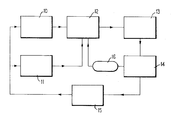
- an optical sensor 10 for detecting the attitude of an artificial earth satellite.
- This sensor is entirely conventional and will not be described in detail. Its function is to generate electrical signals which represent the attitude of the satellite with respect to a known optical source.
- An inertial sensor 11 is also shown in the drawing. Again the sensor is entirely conventional Both sensors give output signals in accordance with the satellite's attitude to a Kalman filter 12.
- a Kalman filter is essentially a complex electrical analogue or model of the dynamics of the satellite. Thus the signals from the two sensors 10 and 11 are combined in the Kalman filter 12.
- attitude controller 13 As any variation in the signals from the sensors 10 and 11 represents a dynamic change in the satellite system modelled by the Kalman filter, this produces appropriate output signals which are supplied by Kalman filter 12 to an attitude controller 13.
- the attitude controller 13 generates the actual control signals which are supplied to the actuators which control the attitude of the satellite.
- the actuators are thrusters 14.
- the thrusters may be hot gas thrusters making use of catalytic decomposition of monopropellants such as hydrazine, though many other types of bipropellant or cold gas thrusters can also be used.
- a conventional attitude control system employing an attitude sensor and a Kalman filter the control signals from the attitude controller are fed back to the Kalman filter to provide a feed back loop so that the Kalman filter continues to model the dynamics of the satellite.
- the effect of the thrusters is to alter the satellite dynamics as is indicated in box 15 of the accompanying drawing which in turn alters the inputs to attitude sensors 10 and 11.
- reaction chamber pressure transducers 16 are fitted not only for test purposes but for operational use. Furthermore it is the outputs of the permanently fitted reaction chamber pressure transducers 16 which are fed to the Kalman filter 12 rather than the control signals from the attitude controller 13.
- the relationship between the pressure transducer signals and the actual thrust generated by the thrusters is closer than the relationship between the control signals from attitude controller 13 and the actual thrust. This enables a much more precise estimate of the attitude state of the satellite to be made by the Kalman filter. This is a particular advantage when the satellite attitude control system does not employ an inertial sensor and also when accurate measurements of the rate of rotation of the satellite form part of the estimated attitude state.
- satellite as used in this specification is intended to cover space vehicles other than those which are merely in orbit.
- the Kalman filter need not necessarily be located within the actual spacecraft. Thus it can be earth-based with the measurements from the pressure transducers 16 transmitted to the earth station via the normal satellite communication channels.
- One way in which the information could be transmitted is by taking an integral of the measured values over a given pulse of operation.
Landscapes
- Engineering & Computer Science (AREA)
- Remote Sensing (AREA)
- Automation & Control Theory (AREA)
- Chemical & Material Sciences (AREA)
- Combustion & Propulsion (AREA)
- Radar, Positioning & Navigation (AREA)
- Aviation & Aerospace Engineering (AREA)
- Control Of Position, Course, Altitude, Or Attitude Of Moving Bodies (AREA)
Applications Claiming Priority (2)
| Application Number | Priority Date | Filing Date | Title |
|---|---|---|---|
| GB868616385A GB8616385D0 (en) | 1986-07-04 | 1986-07-04 | Satellite attitude control |
| GB8616385 | 1986-07-04 |
Publications (2)
| Publication Number | Publication Date |
|---|---|
| EP0251808A2 true EP0251808A2 (de) | 1988-01-07 |
| EP0251808A3 EP0251808A3 (de) | 1988-07-27 |
Family
ID=10600596
Family Applications (1)
| Application Number | Title | Priority Date | Filing Date |
|---|---|---|---|
| EP87305898A Withdrawn EP0251808A3 (de) | 1986-07-04 | 1987-07-03 | Satelliten-Lageregelung |
Country Status (4)
| Country | Link |
|---|---|
| US (1) | US4786018A (de) |
| EP (1) | EP0251808A3 (de) |
| JP (1) | JPS6341299A (de) |
| GB (2) | GB8616385D0 (de) |
Cited By (7)
| Publication number | Priority date | Publication date | Assignee | Title |
|---|---|---|---|---|
| EP0363243A1 (de) * | 1988-10-06 | 1990-04-11 | AEROSPATIALE Société Nationale Industrielle | Verfahren und Vorrichtung zur autonomen Steuerung einer geostationären satellitenumlaufbahn |
| EP0769736A1 (de) * | 1990-04-16 | 1997-04-23 | Space Systems / Loral Inc. | Methode zur Steuerung der Lage eines durch Eigenrotation stabilisierten Satelliten in einer geneigten Umlaufbahn |
| GB2318888A (en) * | 1996-10-30 | 1998-05-06 | Motorola Inc | Solar panel mounted sun sensor and three-axis attitude control |
| GB2360099A (en) * | 2000-03-07 | 2001-09-12 | Matra Marconi Space | Attitude control system for a spacecraft |
| CN101907039A (zh) * | 2010-07-23 | 2010-12-08 | 北京航空航天大学 | 一种采用三圆柱推进剂贮箱的氮气冷气微推进装置 |
| CN103699131A (zh) * | 2013-12-26 | 2014-04-02 | 北京控制工程研究所 | 一种卫星控制系统离散积分滑模容错控制方法 |
| CN104503233A (zh) * | 2014-11-27 | 2015-04-08 | 哈尔滨工业大学 | 适用于卫星姿态控制的干扰力矩辨识方法 |
Families Citing this family (10)
| Publication number | Priority date | Publication date | Assignee | Title |
|---|---|---|---|---|
| DE19703629A1 (de) * | 1997-01-31 | 1998-08-06 | Daimler Benz Aerospace Ag | Verfahren zur bordautonomen Bestimmung der Position eines Satelliten |
| US5098041A (en) * | 1990-06-07 | 1992-03-24 | Hughes Aircraft Company | Attitude control system for momentum-biased spacecraft |
| FR2666561B1 (fr) * | 1990-09-06 | 1995-06-09 | Aerospatiale | Procede de pilotage d'un engin spatial dote d'un mouvement de precession et dispositif pour sa mise en óoeuvre. |
| DE4243395C2 (de) * | 1991-12-21 | 1997-05-22 | Deutsche Forsch Luft Raumfahrt | Anordnung zur koordinierten Positionshaltung eines geostationären Satellitenschwarms |
| JPH05172562A (ja) * | 1991-12-24 | 1993-07-09 | Nec Corp | 姿勢センサ装置 |
| US5546309A (en) * | 1993-10-20 | 1996-08-13 | The Charles Stark Draper Laboratory, Inc. | Apparatus and method for autonomous satellite attitude sensing |
| US5935176A (en) * | 1996-11-22 | 1999-08-10 | Lockheed Martin Corporation | Momentum wheel oscillation filter |
| US6577929B2 (en) | 2001-01-26 | 2003-06-10 | The Charles Stark Draper Laboratory, Inc. | Miniature attitude sensing suite |
| US7090170B1 (en) * | 2002-11-22 | 2006-08-15 | Honeywell International, Inc. | In-orbit satellite sensor alignment determination |
| US8528316B2 (en) * | 2009-04-23 | 2013-09-10 | Honeywell International Inc. | Solid propellant gas control system and method |
Family Cites Families (10)
| Publication number | Priority date | Publication date | Assignee | Title |
|---|---|---|---|---|
| US4010921A (en) * | 1975-08-20 | 1977-03-08 | The United States Of America As Represented By The Secretary Of The Air Force | Spacecraft closed loop three-axis momentum unloading system |
| US4071211A (en) * | 1976-09-23 | 1978-01-31 | Rca Corporation | Momentum biased active three-axis satellite attitude control system |
| FR2393364A1 (fr) * | 1977-05-31 | 1978-12-29 | Aerospatiale | Procede et systeme integre de controle de couple et de conditionnement d'energie pour vehicule spatial |
| DE2732201C2 (de) * | 1977-07-16 | 1983-01-13 | Messerschmitt-Bölkow-Blohm GmbH, 8000 München | Regler für die Lagestabilisierung eines Satelliten |
| US4294420A (en) * | 1978-01-30 | 1981-10-13 | Matra | Attitude control systems for space vehicles |
| FR2447320A1 (fr) * | 1979-01-23 | 1980-08-22 | Matra | Perfectionnements aux procedes et dispositifs d'amortissement actif de nutation pour vehicule spatial |
| DE3071249D1 (en) * | 1980-08-19 | 1986-01-02 | Messerschmitt Boelkow Blohm | Attitude control device for elastic vehicles |
| US4437047A (en) * | 1981-07-13 | 1984-03-13 | Hughes Aircraft Company | System for autonomous earth-pointing acquisition of a dual-spin satellite |
| US4521855A (en) * | 1981-07-27 | 1985-06-04 | Ford Aerospace & Communications Corporation | Electronic on-orbit roll/yaw satellite control |
| DE3214378C2 (de) * | 1982-04-20 | 1985-12-19 | Messerschmitt-Bölkow-Blohm GmbH, 8000 München | Einrichtung für die Schwungrad-Regelung eines Satelliten |
-
1986
- 1986-07-04 GB GB868616385A patent/GB8616385D0/en active Pending
-
1987
- 1987-06-29 JP JP62162198A patent/JPS6341299A/ja active Pending
- 1987-07-01 US US07/068,968 patent/US4786018A/en not_active Expired - Fee Related
- 1987-07-03 GB GB878715655A patent/GB8715655D0/en active Pending
- 1987-07-03 EP EP87305898A patent/EP0251808A3/de not_active Withdrawn
Cited By (9)
| Publication number | Priority date | Publication date | Assignee | Title |
|---|---|---|---|---|
| EP0363243A1 (de) * | 1988-10-06 | 1990-04-11 | AEROSPATIALE Société Nationale Industrielle | Verfahren und Vorrichtung zur autonomen Steuerung einer geostationären satellitenumlaufbahn |
| FR2637564A1 (fr) * | 1988-10-06 | 1990-04-13 | Aerospatiale | Procede et systeme de controle autonome d'orbite d'un satellite geostationnaire |
| EP0769736A1 (de) * | 1990-04-16 | 1997-04-23 | Space Systems / Loral Inc. | Methode zur Steuerung der Lage eines durch Eigenrotation stabilisierten Satelliten in einer geneigten Umlaufbahn |
| GB2318888A (en) * | 1996-10-30 | 1998-05-06 | Motorola Inc | Solar panel mounted sun sensor and three-axis attitude control |
| GB2360099A (en) * | 2000-03-07 | 2001-09-12 | Matra Marconi Space | Attitude control system for a spacecraft |
| GB2360099B (en) * | 2000-03-07 | 2004-02-11 | Matra Marconi Space | Attitude control system for a spacecraft |
| CN101907039A (zh) * | 2010-07-23 | 2010-12-08 | 北京航空航天大学 | 一种采用三圆柱推进剂贮箱的氮气冷气微推进装置 |
| CN103699131A (zh) * | 2013-12-26 | 2014-04-02 | 北京控制工程研究所 | 一种卫星控制系统离散积分滑模容错控制方法 |
| CN104503233A (zh) * | 2014-11-27 | 2015-04-08 | 哈尔滨工业大学 | 适用于卫星姿态控制的干扰力矩辨识方法 |
Also Published As
| Publication number | Publication date |
|---|---|
| EP0251808A3 (de) | 1988-07-27 |
| GB8616385D0 (en) | 1986-08-13 |
| JPS6341299A (ja) | 1988-02-22 |
| GB8715655D0 (en) | 1987-08-12 |
| US4786018A (en) | 1988-11-22 |
Similar Documents
| Publication | Publication Date | Title |
|---|---|---|
| US4786018A (en) | Satellite attitude control | |
| US4106094A (en) | Strap-down attitude and heading reference system | |
| US4254465A (en) | Strap-down attitude and heading reference system | |
| US6681649B2 (en) | Inertial control and measurement system | |
| US6421622B1 (en) | Dynamic attitude measurement sensor and method | |
| CA1141008A (en) | Autonomous navigation system | |
| US6853947B1 (en) | Dynamic attitude measurement method and apparatus | |
| US5201833A (en) | Attitude control system with reaction wheel friction compensation | |
| EP0496879A4 (en) | Satellite orbit maintenance system | |
| CA2041857A1 (en) | Attitude control system for momentum-biased spacecraft | |
| JPS6047159B2 (ja) | 衛星の姿勢制御装置 | |
| JPH10318778A (ja) | 衛星の位置を機内で自主的に求める方法と装置 | |
| US2968957A (en) | Centripetal acceleration compensation computer for stable platform | |
| US5875676A (en) | Non colocated rate sensing for control moment gyroscopes | |
| WO1998016425A9 (en) | Feedback motion compensation for spacecraft payload | |
| US4132482A (en) | Feedback system for a ring laser gyro | |
| EP1856478A2 (de) | Verfahren und systeme zur verwendung der wahren luftgeschwindigkeit zur verbesserung der vertikalen geschwindigkeitsgenauigkeit | |
| US4675822A (en) | Doppler-inertial data loop for navigation system | |
| Bordany et al. | In-orbit estimation of the inertia matrix and thruster parameters of UoSAT-12 | |
| EP1134640B1 (de) | Lageregelung für ein Raumfahrzeug | |
| Algrain | High-bandwidth attitude jitter determination for pointing and tracking systems | |
| EP0892328A1 (de) | System und Methode zur Positionsregelung eines Satelliten | |
| JPH0920298A (ja) | スラスタ制御装置 | |
| JP2798938B2 (ja) | 三軸姿勢制御装置 | |
| US4888705A (en) | System for measuring the position of vibrating object |
Legal Events
| Date | Code | Title | Description |
|---|---|---|---|
| PUAI | Public reference made under article 153(3) epc to a published international application that has entered the european phase |
Free format text: ORIGINAL CODE: 0009012 |
|
| AK | Designated contracting states |
Kind code of ref document: A2 Designated state(s): DE ES FR IT NL SE |
|
| PUAL | Search report despatched |
Free format text: ORIGINAL CODE: 0009013 |
|
| AK | Designated contracting states |
Kind code of ref document: A3 Designated state(s): DE ES FR IT NL SE |
|
| STAA | Information on the status of an ep patent application or granted ep patent |
Free format text: STATUS: THE APPLICATION IS DEEMED TO BE WITHDRAWN |
|
| 18D | Application deemed to be withdrawn |
Effective date: 19890128 |
|
| RIN1 | Information on inventor provided before grant (corrected) |
Inventor name: COPE, PAUL EDWARD GEORGE |