EP0251814A2 - Graviermaschine - Google Patents
Graviermaschine Download PDFInfo
- Publication number
- EP0251814A2 EP0251814A2 EP87305917A EP87305917A EP0251814A2 EP 0251814 A2 EP0251814 A2 EP 0251814A2 EP 87305917 A EP87305917 A EP 87305917A EP 87305917 A EP87305917 A EP 87305917A EP 0251814 A2 EP0251814 A2 EP 0251814A2
- Authority
- EP
- European Patent Office
- Prior art keywords
- cutter head
- cutter
- engraving machine
- sleeve
- mount
- Prior art date
- Legal status (The legal status is an assumption and is not a legal conclusion. Google has not performed a legal analysis and makes no representation as to the accuracy of the status listed.)
- Withdrawn
Links
Images
Classifications
-
- B—PERFORMING OPERATIONS; TRANSPORTING
- B44—DECORATIVE ARTS
- B44B—MACHINES, APPARATUS OR TOOLS FOR ARTISTIC WORK, e.g. FOR SCULPTURING, GUILLOCHING, CARVING, BRANDING, INLAYING
- B44B3/00—Artists' machines or apparatus equipped with tools or work holders moving or able to be controlled substantially two-dimensionally for carving, engraving, or guilloching shallow ornamenting or markings
- B44B3/06—Accessories, e.g. tool or work holders
- B44B3/061—Tool heads
-
- Y—GENERAL TAGGING OF NEW TECHNOLOGICAL DEVELOPMENTS; GENERAL TAGGING OF CROSS-SECTIONAL TECHNOLOGIES SPANNING OVER SEVERAL SECTIONS OF THE IPC; TECHNICAL SUBJECTS COVERED BY FORMER USPC CROSS-REFERENCE ART COLLECTIONS [XRACs] AND DIGESTS
- Y10—TECHNICAL SUBJECTS COVERED BY FORMER USPC
- Y10T—TECHNICAL SUBJECTS COVERED BY FORMER US CLASSIFICATION
- Y10T408/00—Cutting by use of rotating axially moving tool
- Y10T408/65—Means to drive tool
- Y10T408/675—Means to drive tool including means to move Tool along tool-axis
-
- Y—GENERAL TAGGING OF NEW TECHNOLOGICAL DEVELOPMENTS; GENERAL TAGGING OF CROSS-SECTIONAL TECHNOLOGIES SPANNING OVER SEVERAL SECTIONS OF THE IPC; TECHNICAL SUBJECTS COVERED BY FORMER USPC CROSS-REFERENCE ART COLLECTIONS [XRACs] AND DIGESTS
- Y10—TECHNICAL SUBJECTS COVERED BY FORMER USPC
- Y10T—TECHNICAL SUBJECTS COVERED BY FORMER US CLASSIFICATION
- Y10T409/00—Gear cutting, milling, or planing
- Y10T409/30—Milling
- Y10T409/303416—Templet, tracer, or cutter
-
- Y—GENERAL TAGGING OF NEW TECHNOLOGICAL DEVELOPMENTS; GENERAL TAGGING OF CROSS-SECTIONAL TECHNOLOGIES SPANNING OVER SEVERAL SECTIONS OF THE IPC; TECHNICAL SUBJECTS COVERED BY FORMER USPC CROSS-REFERENCE ART COLLECTIONS [XRACs] AND DIGESTS
- Y10—TECHNICAL SUBJECTS COVERED BY FORMER USPC
- Y10T—TECHNICAL SUBJECTS COVERED BY FORMER US CLASSIFICATION
- Y10T409/00—Gear cutting, milling, or planing
- Y10T409/30—Milling
- Y10T409/306664—Milling including means to infeed rotary cutter toward work
- Y10T409/30672—Milling including means to infeed rotary cutter toward work with means to limit penetration into work
Definitions
- This invention relates to engraving machines.
- Machines for engraving e.g. the surface of plates have a platen for holding the plate, and a carriage supporting a rotatable milling cutter head above the platen.
- the cutter head can be moved by servo motors in the X and Y directions, and between a raised non-cutting position and a lowered cutting position.
- the movements can be controlled by a computer program to produce pre-determined patterns of engraving on the plate.
- the height of the lowered cutting position of the cutter head is adjusted manually and set before the engraving operation is started. If it is to be altered, it can only be adjusted manually after completion of a pass over the plate.
- the cutter head itself permits a second manual adjustment, namely the projection of the milling cutter from a nose cone which in use bears under spring pressure against the surface of the plate.
- the projection thus decides the depth of the engraving.
- the desired depth of engraving can only be achieved by a number of passes over the plate with the cutter at progressively increased projections. Again the adjustment can only be done manually between passes.
- the pressure of the nose cone on its surface may cause scratching, so a nose cone is dispensed with.
- the depth of incision is decided by the absolute height of the cutter head. The evenness of the incision over the plate then depends upon the plate being held flat on the platen for example by a vacuum.
- the invention aims to provide an engraving machine which reduces or avoids the disadvantages of existing machines, by making the depth of cut control more flexible and responsive to computer control.
- the invention proposes an engraving machine having a cutter head movable in X and Y directions above a platen for holding a workpiece, the cutter head on a mount being movable bodily in the Z direction between a raised position and a lowered working position, wherein the cutter head is adjustable by a servo motor to adjust the projection of a cutter relative to the cutter head.
- the same motor is usable to adjust the cutter head relative to the mount in the Z direction, and a selector decides which adjustment is made.
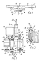
- Fig.l shows schematically the main functional units of an engraving machine cutter section, that is excluding the platen for receiving the workpiece.
- the cutter section has a beam l0 movable in the Y direction ll, and a carriage l2 movable along the beam l0 in the X direction l3.
- a cutter unit l4 is movable on a slide l5 in the Z direction perpendicular to the plane of the drawing by means of a solenoid unit l6.
- the cutter unit l4 comprises a cutter plate l7 which carries a cutter head l8 driven by a drive motor l9.
- the head l8 is movable again in the Z direction on the plate l7 by means of a stepping motor 20.
- the solenoid unit l6 and the cutter unit l4 with its constituent parts are shown in detail in Fig.2.
- the solenoid unit l6 mounted on carriage l2 is linked by an arm 22 to the cutter plate l7.
- the armature 23 of the solenoid is moved up and down between end positions, determined by an adjuster nut 24, carrying with it a rod 25 linked to the arm 22. Movement is damped by a spring 26 and the downward pressure of the cutter unit on the workpiece is maintained by a spring 27.
- the motor unit is mounted by two brackets 28 for sliding movements on a vertical rod 29 fixed on the carriage l2.
- the cutter head is driven by a belt 3l from the drive motor l9.
- a milling cutter 32 projects from a nose cone 33 by an amount which determines the depth of the engraved pattern in the workpiece.
- the cutter 32 is integral with a drive spindle 35, which rotates within the nose cone 33 and an integral externally toothed cap 36.
- the latter is internally threaded at 37 and screwed on an external thread on a sleeve 38.
- the cap 36 By rotation of the cap 36, the nose cone is raised and lowered relative to the cutter 32 and spindle 35 which is journalled in bearings in the sleeve 38.
- the sleeve 38 itself is externally threaded at 40 and is rotatable within an outer housing 4l which is fixed on the cutter plate l7.
- a selector key 42 is slidable on a pin 43 on the sleeve 38 between an upper position in which the sleeve 38 is locked to the outer housing 4l, and a lower position (as shown) in which the cap 36 is locked to the sleeVe 38.
- the stepping motor 20 also fixed to the plate l7 drives the cap 36 by a toothed belt 44.
- the motor 20 rotates the cap 36 and the sleeve 38 together relative to the outer housing 4l so that the cutter 32 and the nose cone 33 are moved in unison relative to the cutter plate l7.
- the nose cone 33 is not required and can be detached from the cap 36.
- the cap 36 moves up and down relative to the spindle 35 and cutter 32, thus adjusting the projection of the cutter.
- the control can be programmed in terms of drive of the stepping motor which, depending upon the setting of the selector key 42, controls either the absolute height of the cutter or the projection of the cutter through the nose cone.
- movement of the key 42 can also be effected by a solenoid, the operation of which can also then be programmed with the other controls so that the entire operation of the machine is carried out under computer control.
Landscapes
- Control Of Cutting Processes (AREA)
Applications Claiming Priority (2)
| Application Number | Priority Date | Filing Date | Title |
|---|---|---|---|
| GB8616380 | 1986-07-04 | ||
| GB868616380A GB8616380D0 (en) | 1986-07-04 | 1986-07-04 | Engraving machine |
Publications (2)
| Publication Number | Publication Date |
|---|---|
| EP0251814A2 true EP0251814A2 (de) | 1988-01-07 |
| EP0251814A3 EP0251814A3 (de) | 1989-08-23 |
Family
ID=10600594
Family Applications (1)
| Application Number | Title | Priority Date | Filing Date |
|---|---|---|---|
| EP87305917A Withdrawn EP0251814A3 (de) | 1986-07-04 | 1987-07-03 | Graviermaschine |
Country Status (3)
| Country | Link |
|---|---|
| US (1) | US4836721A (de) |
| EP (1) | EP0251814A3 (de) |
| GB (1) | GB8616380D0 (de) |
Cited By (3)
| Publication number | Priority date | Publication date | Assignee | Title |
|---|---|---|---|---|
| GB2225290A (en) * | 1988-09-29 | 1990-05-30 | Ando Electric | Engraving device having double return mechanism of penholder supporter |
| EP0569672A1 (de) * | 1992-05-11 | 1993-11-18 | Otto Borries KG | Vorrichtung zum Einformen einer Beschriftung an einer kegeligen oder kegelähnlichen Fläche von rotationssymmetrischen Körpern |
| CN103591152A (zh) * | 2012-08-16 | 2014-02-19 | 苏州市兴博塑胶模具有限公司 | 一种主轴卡具 |
Families Citing this family (3)
| Publication number | Priority date | Publication date | Assignee | Title |
|---|---|---|---|---|
| US5311667A (en) * | 1993-03-02 | 1994-05-17 | Brady Usa, Inc. | Method and apparatus for adjusting line width in a sign engraving machine |
| FR2849549B1 (fr) * | 2002-12-27 | 2005-10-07 | Gravograph Ind Internat | Moteur electrique a axe creux et machine a graver le mettant en oeuvre |
| JP2015502867A (ja) * | 2011-09-30 | 2015-01-29 | カナディアン バンク ノート カンパニー,リミテッド | 触覚機能作成ツール |
Family Cites Families (16)
| Publication number | Priority date | Publication date | Assignee | Title |
|---|---|---|---|---|
| GB389102A (en) * | 1931-06-09 | 1933-03-09 | John Willey Dalton | Improvements in and relating to engraving |
| FR945725A (fr) * | 1947-04-11 | 1949-05-12 | Machine à graver et à reproduire | |
| FR999529A (fr) * | 1949-11-10 | 1952-02-01 | Forezienne D Ind Mecanique Soc | Tête mobile à commande directe pour machine à graver |
| US2638500A (en) * | 1951-06-28 | 1953-05-12 | Clare E Ernst | Process and apparatus for photoelectric engraving |
| US2723598A (en) * | 1951-12-26 | 1955-11-15 | Ekstrom Carlson & Co | Power actuated router |
| US2874479A (en) * | 1955-07-15 | 1959-02-24 | Fairchild Camera Instr Co | Engraving machine stylus index |
| US3166987A (en) * | 1962-06-14 | 1965-01-26 | Western Electric Co | Device for controlling the cutting depth of a tool |
| US3891015A (en) * | 1972-09-05 | 1975-06-24 | Olin Corp | Constant depth cutter assembly |
| US4037982A (en) * | 1974-09-11 | 1977-07-26 | Infranor S.A. | Machine tools |
| DE2728794C2 (de) * | 1977-06-25 | 1984-03-29 | Aristo Graphic Systeme Gmbh & Co Kg, 2000 Hamburg | Fräskopf zum Ausschneiden von Schablonen aus Karton o.dgl. |
| US4273482A (en) * | 1978-07-03 | 1981-06-16 | Conti-Form Machine Tools Limited | Automatic tool-moving machine |
| FR2437909A1 (fr) * | 1978-10-06 | 1980-04-30 | Vierstraete Jean | Dispositif tournant de compression de pieces plates fixe sur un des elements d'usinage d'une machine-outil |
| FR2459111A1 (fr) * | 1979-06-15 | 1981-01-09 | Sormel Sa | Automate de manipulation precise a cadence elevee |
| US4382728A (en) * | 1979-10-25 | 1983-05-10 | The Boeing Company | Workpiece retaining pressure-foot assembly for orthogonally movable machine tool |
| US4515505A (en) * | 1982-10-28 | 1985-05-07 | International Business Machines Corporation | Pressure foot assembly for an end mill delete cutter |
| US4717291A (en) * | 1986-10-06 | 1988-01-05 | The Boeing Company | Automatic countersink depth control tool for fastener installer |
-
1986
- 1986-07-04 GB GB868616380A patent/GB8616380D0/en active Pending
-
1987
- 1987-07-03 EP EP87305917A patent/EP0251814A3/de not_active Withdrawn
- 1987-07-06 US US07/070,027 patent/US4836721A/en not_active Expired - Fee Related
Cited By (3)
| Publication number | Priority date | Publication date | Assignee | Title |
|---|---|---|---|---|
| GB2225290A (en) * | 1988-09-29 | 1990-05-30 | Ando Electric | Engraving device having double return mechanism of penholder supporter |
| EP0569672A1 (de) * | 1992-05-11 | 1993-11-18 | Otto Borries KG | Vorrichtung zum Einformen einer Beschriftung an einer kegeligen oder kegelähnlichen Fläche von rotationssymmetrischen Körpern |
| CN103591152A (zh) * | 2012-08-16 | 2014-02-19 | 苏州市兴博塑胶模具有限公司 | 一种主轴卡具 |
Also Published As
| Publication number | Publication date |
|---|---|
| US4836721A (en) | 1989-06-06 |
| GB8616380D0 (en) | 1986-08-13 |
| EP0251814A3 (de) | 1989-08-23 |
Similar Documents
| Publication | Publication Date | Title |
|---|---|---|
| DE69512535T2 (de) | Verfahren und vorrichtung zum polieren von edelsteinen | |
| DE102009006797B4 (de) | Linsenbearbeitungsvorrichtung | |
| EP0126037B1 (de) | Vorrichtung zum Schneiden von Flachglasscheiben nach einem programmierten Profil | |
| EP0131743A2 (de) | Kalibrierungsmessgerät für einen computergesteuerten Linsengenerator oder dergleichen | |
| US4836721A (en) | Engraving machine | |
| KR100435331B1 (ko) | 밀링 머신용 지그 | |
| US5511598A (en) | Veneer-slicer with remotely controllable blade angle adjustment | |
| JP4327857B2 (ja) | ディジタル制御式穿孔装置を用いて光学レンズに穴を開ける方法と、その方法を実施する装置 | |
| US4517870A (en) | Machine for manufacturing a template for edge grinding a spectacle lens | |
| JPH04217492A (ja) | シート材料裁断機械 | |
| JP2794505B2 (ja) | 加工圧制御装置 | |
| US3702604A (en) | Work mounting mechanism in slicing machine | |
| GB2274801A (en) | Sheet cutting apparatus | |
| CN212218617U (zh) | 一种全方位切割机 | |
| US4737053A (en) | Automatic machine for shaping the external profile of spectacle lenses | |
| CN113770550A (zh) | 一种带有角度自动调节功能的智能化激光切割机 | |
| US4524544A (en) | Machine for backing-off and/or grinding drifting spindles provided with teeth | |
| US4995300A (en) | Lathe for generating aspherical surfaces on work pieces | |
| US6782883B2 (en) | Cutting device for breaking fragile materials such as semiconductor wafers or the like | |
| US4909679A (en) | Plastic lens edge beveler | |
| EP0583291B1 (de) | Maschine zum schaerfen von saegeblaettern | |
| US3942287A (en) | Contour grinders | |
| US5074346A (en) | Tire grooving apparatus | |
| EP1072358B1 (de) | Glasscheibenrand-Bearbeitungsvorrichtung | |
| JP4517269B2 (ja) | Z補正付ダイシング装置 |
Legal Events
| Date | Code | Title | Description |
|---|---|---|---|
| PUAI | Public reference made under article 153(3) epc to a published international application that has entered the european phase |
Free format text: ORIGINAL CODE: 0009012 |
|
| AK | Designated contracting states |
Kind code of ref document: A2 Designated state(s): DE FR GB |
|
| PUAL | Search report despatched |
Free format text: ORIGINAL CODE: 0009013 |
|
| AK | Designated contracting states |
Kind code of ref document: A3 Designated state(s): DE FR GB |
|
| STAA | Information on the status of an ep patent application or granted ep patent |
Free format text: STATUS: THE APPLICATION IS DEEMED TO BE WITHDRAWN |
|
| 18D | Application deemed to be withdrawn |
Effective date: 19890801 |
|
| RIN1 | Information on inventor provided before grant (corrected) |
Inventor name: CAMPLING, BRIAN |