EP0251836A1 - Vollständiges Wärmerohr-Modul - Google Patents
Vollständiges Wärmerohr-Modul Download PDFInfo
- Publication number
- EP0251836A1 EP0251836A1 EP87401180A EP87401180A EP0251836A1 EP 0251836 A1 EP0251836 A1 EP 0251836A1 EP 87401180 A EP87401180 A EP 87401180A EP 87401180 A EP87401180 A EP 87401180A EP 0251836 A1 EP0251836 A1 EP 0251836A1
- Authority
- EP
- European Patent Office
- Prior art keywords
- heat pipe
- condenser
- integral heat
- wick
- component
- Prior art date
- Legal status (The legal status is an assumption and is not a legal conclusion. Google has not performed a legal analysis and makes no representation as to the accuracy of the status listed.)
- Granted
Links
Images
Classifications
-
- H—ELECTRICITY
- H10—SEMICONDUCTOR DEVICES; ELECTRIC SOLID-STATE DEVICES NOT OTHERWISE PROVIDED FOR
- H10W—GENERIC PACKAGES, INTERCONNECTIONS, CONNECTORS OR OTHER CONSTRUCTIONAL DETAILS OF DEVICES COVERED BY CLASS H10
- H10W40/00—Arrangements for thermal protection or thermal control
- H10W40/70—Fillings or auxiliary members in containers or in encapsulations for thermal protection or control
- H10W40/73—Fillings or auxiliary members in containers or in encapsulations for thermal protection or control for cooling by change of state
-
- F—MECHANICAL ENGINEERING; LIGHTING; HEATING; WEAPONS; BLASTING
- F28—HEAT EXCHANGE IN GENERAL
- F28D—HEAT-EXCHANGE APPARATUS, NOT PROVIDED FOR IN ANOTHER SUBCLASS, IN WHICH THE HEAT-EXCHANGE MEDIA DO NOT COME INTO DIRECT CONTACT
- F28D15/00—Heat-exchange apparatus with the intermediate heat-transfer medium in closed tubes passing into or through the conduit walls ; Heat-exchange apparatus employing intermediate heat-transfer medium or bodies
- F28D15/02—Heat-exchange apparatus with the intermediate heat-transfer medium in closed tubes passing into or through the conduit walls ; Heat-exchange apparatus employing intermediate heat-transfer medium or bodies in which the medium condenses and evaporates, e.g. heat pipes
- F28D15/0233—Heat-exchange apparatus with the intermediate heat-transfer medium in closed tubes passing into or through the conduit walls ; Heat-exchange apparatus employing intermediate heat-transfer medium or bodies in which the medium condenses and evaporates, e.g. heat pipes the conduits having a particular shape, e.g. non-circular cross-section, annular
-
- F—MECHANICAL ENGINEERING; LIGHTING; HEATING; WEAPONS; BLASTING
- F28—HEAT EXCHANGE IN GENERAL
- F28D—HEAT-EXCHANGE APPARATUS, NOT PROVIDED FOR IN ANOTHER SUBCLASS, IN WHICH THE HEAT-EXCHANGE MEDIA DO NOT COME INTO DIRECT CONTACT
- F28D15/00—Heat-exchange apparatus with the intermediate heat-transfer medium in closed tubes passing into or through the conduit walls ; Heat-exchange apparatus employing intermediate heat-transfer medium or bodies
- F28D15/02—Heat-exchange apparatus with the intermediate heat-transfer medium in closed tubes passing into or through the conduit walls ; Heat-exchange apparatus employing intermediate heat-transfer medium or bodies in which the medium condenses and evaporates, e.g. heat pipes
- F28D15/04—Heat-exchange apparatus with the intermediate heat-transfer medium in closed tubes passing into or through the conduit walls ; Heat-exchange apparatus employing intermediate heat-transfer medium or bodies in which the medium condenses and evaporates, e.g. heat pipes with tubes having a capillary structure
- F28D15/046—Heat-exchange apparatus with the intermediate heat-transfer medium in closed tubes passing into or through the conduit walls ; Heat-exchange apparatus employing intermediate heat-transfer medium or bodies in which the medium condenses and evaporates, e.g. heat pipes with tubes having a capillary structure characterised by the material or the construction of the capillary structure
-
- H—ELECTRICITY
- H10—SEMICONDUCTOR DEVICES; ELECTRIC SOLID-STATE DEVICES NOT OTHERWISE PROVIDED FOR
- H10W—GENERIC PACKAGES, INTERCONNECTIONS, CONNECTORS OR OTHER CONSTRUCTIONAL DETAILS OF DEVICES COVERED BY CLASS H10
- H10W72/00—Interconnections or connectors in packages
- H10W72/071—Connecting or disconnecting
- H10W72/072—Connecting or disconnecting of bump connectors
- H10W72/07251—Connecting or disconnecting of bump connectors characterised by changes in properties of the bump connectors during connecting
-
- H—ELECTRICITY
- H10—SEMICONDUCTOR DEVICES; ELECTRIC SOLID-STATE DEVICES NOT OTHERWISE PROVIDED FOR
- H10W—GENERIC PACKAGES, INTERCONNECTIONS, CONNECTORS OR OTHER CONSTRUCTIONAL DETAILS OF DEVICES COVERED BY CLASS H10
- H10W72/00—Interconnections or connectors in packages
- H10W72/20—Bump connectors, e.g. solder bumps or copper pillars; Dummy bumps; Thermal bumps
-
- H—ELECTRICITY
- H10—SEMICONDUCTOR DEVICES; ELECTRIC SOLID-STATE DEVICES NOT OTHERWISE PROVIDED FOR
- H10W—GENERIC PACKAGES, INTERCONNECTIONS, CONNECTORS OR OTHER CONSTRUCTIONAL DETAILS OF DEVICES COVERED BY CLASS H10
- H10W72/00—Interconnections or connectors in packages
- H10W72/851—Dispositions of multiple connectors or interconnections
- H10W72/874—On different surfaces
- H10W72/877—Bump connectors and die-attach connectors
Definitions
- This invention relates to a heat pipe for cooling electronic components, and more particularly to an integral heat pipe module for cooling semiconductor chips.
- Cooling fins large enough to properly disipate the heat generated by a chip would be so large that supplying them would defeat the purpose of having a miniaturized chip. Cooling fans are unsuitable for the same reason. Furthermore, many cooling fans large enough to adequately cool integrated circuit chips weigh more and consume more power that the chips themselves.
- modules have a mechanical member with relatively low thermal resistance in contact with the surface of the chip.
- the mechanical member provides a conductive path to transfer the heat generated by the chip to a heat sink.
- These modules impose a mechanical stress on the chip because of the physical contact of the mechanical member. This stress is aggravated because the thermal expansion characteristics of the chip and mechanical member are usually significantly different. Also, because each module has a large number of components, they are relatively expensive to manufacture.
- Heat pipes have also been used to dissipate heat generated by semiconductor chips.
- Heat pipes are closed systems having a two-phase working fluid inside a container.
- the working fluid has a vaporization temperature within the operative temperature range of the chips to be cooled.
- One end of the heat pipe is exposed to the component to be cooled and the opposite end is exposed to a heat sink.
- the heat generated by the chip vaporizes the working fluid in the adjacent section of the pipe.
- the vapor travels to the cooler regions of the pipe.
- the latent heat of vaporization is then transferred by conduction to the heak sink, and the vapor condenses.
- the condensed liquid is transferred back to the end of the pipe adjacent to the component to repeat the cycle.
- the integral heat pipe is the other type of heat pipe. It is built into the electronic component package, or module. One or more chips are directly exposed to the working fluid. In many of these heat pipes the chips are located in the bottom of a liquid pool. The heat is transferred from the chips to the fluid by nucleate boiling. If the heat flux from a chip becomes too great, a vapor bubble may form around the chip. The bubble forms an insulating layer that effectively stops further evaporation and heat transfer.
- Some integral heat pipes require a wick inside the module. Often the wick is a glass fiber or dielectric powder that is affixed to the chips and the interior of the module. These wicks may place a mechanical stress on the chips. Also, inserting the wick inside the module adds significantly to the cost of manufacturing the heat pipe.
- the new apparatus should be able to efficiently transfer the heat away from the chips so the chips will remain within the range of their operating temperature. Furthermore, it should be able to transfer heat way from the chips regardless of their heat flux.
- the new apparatus should also be small so that its use will not defeat the advantage of miniaturized components. Also, it should not rely on an external source of power, should not subject the chip to undue mechanical stress, and should be relatively economical to produce.
- This invention comprises an integral heat pipe module where the semiconductor chips are mounted on a substrate and the substrate functions as the base or input end of the heat pipe module.
- a condenser cap is attached to the substrate to form a sealed pipe chamber around the chips.
- the top of the cap, opposite the substrate, is provided with a fluted condenser surface.
- a multi-layer fibrous wick may be located between tops of the chips and the bottom of the condenser surface.
- the tops of the chips may be provided with a grooved surface in contact with the wick.
- the pipe chamber is supplied with a neutral two-phase working fluid and sealed.
- the top of the module or output can be provided with an appropriate heat sink.
- the working fluid is split into vapor phase and liquid phase fractions.
- the liquid portion is on, or adjacent to, the chips as a relatively thin film, or contained within the wick.
- the heat produced by the chips evaporates the thin film of liquid adjacent the chips.
- the vapor moves to the fluted condenser surfaces at the top of module.
- the heat sink extracts the latent heat of vaporization, causing the vapor to condense.
- the recondensed liquid returns to the base of the heat pipe to repeat the cooling cycle.
- the fluted condenser surface at the top of the heat pipe has sufficient surface area to conduct large quantities of latent heat away from the vapor per unit of time. This makes the module very efficient at transferring heat away from the chips. Since there is only a thin film of liquid in contact with the chips the liquid evaporates readily. Also, there is almost no possibility that a vapor bubble will form over the chips, inhibiting the heat transfer process. Adding the wick increases the heat transfer characteristics of the module, yet the stress the wick places on the chip is minimal. When the grooved chip is provided with a grooved top surface an inverted meniscus forms between the liquid in the wick and the chip. The meniscus enhances the evaporation efficiency of the chip, increasing the overall heat transfer characteristics of the heat pipe module.
- the heat pipe module is relatively small and can be designed for use with just one or two chips.
- the module does not have any moving parts and does not require any external power. Furthermore, only a few parts are needed to assemble this heat pipe module, and even with the wick, it is relatively economical to produce.
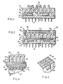
- an integral heat pipe module l0 is provided with one or more electrical components, here semiconductor chips l2, bonded to a substrate l4.
- the substrate is provided with a number of external leads l6 so the module can be connected to the electrical unit for which it was designed.
- a condenser cap l8 is fastened over the substrate and defines a chamber 20 around the chips.
- the condenser cap has a lip 22 that extends around the perimeter of the substrate for securing it to the substrate.
- a sealing ring 24 is located between the top perimeter of the substrate and the cap lip to provide a hermetic seal around the pipe chamber.
- the top of the condenser cap is provided with a number of cooling fins 25.
- a condenser surface 26 is located under the condenser cap l8 opposite the chips l2.
- the condenser surface is provided with a number of parallel flutes 28 that extend the length of the cap.
- Each flute has vertically oriented sidewalls 30 and a top 32 with a semicircular cross-section.
- the condenser cap may also be provided with cross cuts 29 extending across the condenser surface, perpendicular to the flutes 28 and thereby interconnecting the flutes.
- a two-phase working fluid 33 Prior to sealing of the heat pipe module l0, a two-phase working fluid 33 is injected into the chamber 20.
- the ideal fluid is one that is chemically compatible with the module components inside the chamber, relatively non-toxic, a dielectric, and has a boiling point within the operative temperature range of the chips. In its liquid phase the working fluid should have a low viscosity and a high surface tension. Pentane is a relatively ideal working fluid for many applications.
- the chamber 20 should be filled to approximately 50% of its volume with liquid working fluid.
- liquid working fluid For a chamber 20 having dimensions of 5.l cm ⁇ 5.l cm ⁇ 0.3 cm, approximately l cc of working fluid was used.
- the fluid should be pressurized so there is a liquid fraction 34 of fluid is located in the bottom of the chamber, around or over the chips, and a vapor fraction in a space 35 above the liquid fraction.
- the fluid For pentane the fluid should be at approximately one atmospheric pressure.
- a thin film 39 of the liquid fraction of the working fluid covers the chips by virtue of the capillary binding action between the chips l2 and the condenser surface 26.
- the integral heat pipe module l0 functions when the chips generate heat.
- the thin film 39 of liquid working fluid 34 is in direct contact with the chip and absorbs the heat generated by them. Heat is transferred away from the chips by thin film evaporation of the liquid. The vapor travels towards the condenser surface 26, carrying with it the latent heat of evaporation. The condenser surface conducts the latent heat away from the vapor towards the cooling fins 25.
- the flutes 28 provide the condensor surface 26 with sufficient area so a large quantity of latent heat may be conducted away from the vapor at any one time.
- the vapor condenses and the liquid returns to the bottom of the chamber so the cycle can repeat.
- the cross cuts 29 provide a way for the liquid and vapor to flow between the flutes. This keeps the vapor dispersed throughout the flutes so that the liquid condenses out over the whole of the condenser surface. This also alleviates flooding of the low portion of the module if the module l0 is tilted from horizontal.
- the integral heat pipe module l0 ⁇ depicted in Fig. 2 is provided with additional features.
- a multi-layerd fibrous wick 36 is located between and in contact with the tops of the chips l2 ⁇ , l2 ⁇ and the bottom of the condenser surface 26.
- the wick is formed of multiple layers of polyester woven fabric 36a-h, as Fig. 4 illustrates, the Layer 36a in contact with the chips l2 ⁇ , l2 ⁇ 42l mesh (42l strands per inch); the intermediate layers 36b-g are 302.4 mesh, and the layer 36h in contact with the condenser surface 26 is 208 mesh.
- the top surface of the chip l2 ⁇ is provided with parallel micro grooves l5.
- the micro grooves extend across the chip and have a pitch density of approximately 60 grooves/cm.
- a chip l2 ⁇ may be provided with a grooved evaporator cap l3.
- the evaporator cap eliminates the possibility that the chip l2 ⁇ will be damaged during a grooving process. If an evaporator cap is provided, it should be formed of the same material as the chip to avoid stresses caused by the differential thermal expansion. The cap should be attached with an adhesive having a relatively low thermal resistance.
- a cold plate 38 is attached to the top of the condenser cap l8 ⁇ by screws 40.
- the cooling plate has an inlet 42, a cooling chamber 44, and an outlet 46. This allows a cooling fluid, such as water to be circulated through the cold plate.
- the wick 36 insures that the tops of the chips are always in contact with a liquid fraction of the working fluid. Specifically, the separate layers of the wick are pressed together to form a single porous structure. The capillary pumping action of the wick keeps the entire wick saturated with liquid and this keeps the top of the Chips exposed to a thin film 53, depicted in Figure 4, of liquid working fluid that readily evaporates. Since the wick is formed of pliant, flexible material, the stress it exerts on the chips is minimal. The wick's pumping action is an important advantage when the module is operated at a tilt from the horizontal. In such instances the capillary pumping action of the wick prevents the working fluid from migrating to the lowest part in the module where it would otherwise collect.
- the grooved top surfaces of the chips enhance the heat transfer efficiency of the evaporation process.
- An inverted meniscus 50 of the liquid working fluid forms between the wick and the grooved top surface.
- the liquid-vapor shear of the meniscus increases the turbulence in the liquid and forms a thin film of liquid around the grooves. This causes the working fluid to evaporate readily.
- the centers of the grooves are liquid-free and provide a path for the saturated vapor to travel to the condenser surface 26. This reduces the vapor content of the space adjacent to the liquid-vapor interface so as to induce additional evaporation into the space.
- the cold plate 38 acts as the heat sink for the latent heat of vaporization transferred by the working fluid.
- the heat pipe l0 can be economically manufactured.
- the module has sufficient heat transfer properties without the wick.
- the wick is formed of an inexpensive fiber and can be provided without appreciably increasing the cost of the module.
- Providing the chips with grooved top surfaces is recommended only if the chip's heat flux is relatively high, e.g., l6W/cm2 or greater.
- the heat pipe module is small enough so that it can be designed for use with just one or two components. Furthermore, since transfer of heat from the chips is by thin film evaporation, there is almost no possibility that an excessive chip heat flux will cause a vapor bubble to form around a chip that would inhibit the heat transfer process.
Landscapes
- Engineering & Computer Science (AREA)
- Life Sciences & Earth Sciences (AREA)
- Sustainable Development (AREA)
- Physics & Mathematics (AREA)
- Thermal Sciences (AREA)
- Mechanical Engineering (AREA)
- General Engineering & Computer Science (AREA)
- Cooling Or The Like Of Semiconductors Or Solid State Devices (AREA)
- Cooling Or The Like Of Electrical Apparatus (AREA)
Applications Claiming Priority (2)
| Application Number | Priority Date | Filing Date | Title |
|---|---|---|---|
| US86950586A | 1986-05-30 | 1986-05-30 | |
| US869505 | 1986-05-30 |
Publications (2)
| Publication Number | Publication Date |
|---|---|
| EP0251836A1 true EP0251836A1 (de) | 1988-01-07 |
| EP0251836B1 EP0251836B1 (de) | 1991-07-17 |
Family
ID=25353667
Family Applications (1)
| Application Number | Title | Priority Date | Filing Date |
|---|---|---|---|
| EP87401180A Expired - Lifetime EP0251836B1 (de) | 1986-05-30 | 1987-05-26 | Vollständiges Wärmerohr-Modul |
Country Status (5)
| Country | Link |
|---|---|
| EP (1) | EP0251836B1 (de) |
| JP (1) | JPH0727999B2 (de) |
| CN (1) | CN1006834B (de) |
| CA (1) | CA1289130C (de) |
| DE (1) | DE3771405D1 (de) |
Cited By (22)
| Publication number | Priority date | Publication date | Assignee | Title |
|---|---|---|---|---|
| DE4019091A1 (de) * | 1990-06-15 | 1991-12-19 | Battelle Institut E V | Waermeableitungseinrichtung fuer halbleiterbauelemente und verfahren zu deren herstellung |
| EP0435473A3 (en) * | 1989-12-29 | 1992-01-02 | Digital Equipment Corporation | Evaporator having etched fiber nucleation sites and method of fabricating same |
| US5453641A (en) * | 1992-12-16 | 1995-09-26 | Sdl, Inc. | Waste heat removal system |
| WO1998000869A1 (de) * | 1996-06-29 | 1998-01-08 | Robert Bosch Gmbh | Anordnung zur wärmeableitung bei chipmodulen auf mehrschicht-keramikträgern, insbesondere multichipmodule |
| US5864176A (en) * | 1997-04-04 | 1999-01-26 | Unisys Corporation | Electro-mechnical subassembly having a greatly reduced thermal resistance between two mating faces by including a film of liquid, that evaporates without leaving any residue, between the faces |
| EP0910235A1 (de) * | 1997-09-30 | 1999-04-21 | Lucent Technologies Inc. | Zusammengesetzte Wärmesenke |
| EP0881675A3 (de) * | 1997-05-30 | 1999-12-08 | Hewlett-Packard Company | Halbleiterpackung mit innerem Wärmerohr |
| FR2783312A1 (fr) * | 1998-09-15 | 2000-03-17 | Matra Marconi Space France | Boucle fluide a pompage capillaire |
| US6735077B2 (en) * | 2001-10-01 | 2004-05-11 | Fujitsu Limited | Thermal diffuser and radiator |
| EP1381083A3 (de) * | 2002-07-11 | 2004-12-08 | Raytheon Company | Verfahren und Vorrichtung zur Kühlung eines Bauteiles |
| KR100460180B1 (ko) * | 2002-04-08 | 2004-12-08 | (주)울텍 | 다공질 실리콘을 이용한 전자 소자 냉각용 히트 파이프 |
| US6957550B2 (en) | 2003-05-19 | 2005-10-25 | Raytheon Company | Method and apparatus for extracting non-condensable gases in a cooling system |
| US7000691B1 (en) | 2002-07-11 | 2006-02-21 | Raytheon Company | Method and apparatus for cooling with coolant at a subambient pressure |
| US7254957B2 (en) | 2005-02-15 | 2007-08-14 | Raytheon Company | Method and apparatus for cooling with coolant at a subambient pressure |
| US7422053B2 (en) | 2002-05-15 | 2008-09-09 | Convergence Technologies (Usa), Llc | Vapor augmented heatsink with multi-wick structure |
| US7907409B2 (en) | 2008-03-25 | 2011-03-15 | Raytheon Company | Systems and methods for cooling a computing component in a computing rack |
| US7908874B2 (en) | 2006-05-02 | 2011-03-22 | Raytheon Company | Method and apparatus for cooling electronics with a coolant at a subambient pressure |
| US7921655B2 (en) | 2007-09-21 | 2011-04-12 | Raytheon Company | Topping cycle for a sub-ambient cooling system |
| US7934386B2 (en) | 2008-02-25 | 2011-05-03 | Raytheon Company | System and method for cooling a heat generating structure |
| US8341965B2 (en) | 2004-06-24 | 2013-01-01 | Raytheon Company | Method and system for cooling |
| US8651172B2 (en) | 2007-03-22 | 2014-02-18 | Raytheon Company | System and method for separating components of a fluid coolant for cooling a structure |
| US9383145B2 (en) | 2005-11-30 | 2016-07-05 | Raytheon Company | System and method of boiling heat transfer using self-induced coolant transport and impingements |
Families Citing this family (8)
| Publication number | Priority date | Publication date | Assignee | Title |
|---|---|---|---|---|
| CN100356555C (zh) * | 2004-03-29 | 2007-12-19 | 台达电子工业股份有限公司 | 散热器 |
| ES2570980T3 (es) * | 2008-05-05 | 2016-05-23 | Univ Cornell | Uso de una membrana de material compuesto |
| KR101070842B1 (ko) * | 2009-06-11 | 2011-10-06 | 주식회사 자온지 | 방열장치 및 이를 구비한 전자장치 |
| CN104867890A (zh) * | 2015-05-07 | 2015-08-26 | 上海交通大学 | 一种用于3d芯片的相变冷却结构 |
| CN105914191B (zh) * | 2016-06-20 | 2018-03-16 | 深圳市宏钢机械设备有限公司 | 一种水冷散热的集成电路封装 |
| JP6848417B2 (ja) * | 2016-12-19 | 2021-03-24 | 日本電気株式会社 | 冷却装置 |
| JP6920115B2 (ja) * | 2017-07-04 | 2021-08-18 | 新光電気工業株式会社 | ヒートパイプ及びヒートパイプの製造方法 |
| CN108278581B (zh) * | 2018-01-28 | 2019-11-29 | 陈攀攀 | 一种led阵列模块的冷却结构 |
Citations (1)
| Publication number | Priority date | Publication date | Assignee | Title |
|---|---|---|---|---|
| GB1435110A (en) * | 1973-08-31 | 1976-05-12 | Atomic Energy Authority Uk | Microcircuit packages |
Family Cites Families (2)
| Publication number | Priority date | Publication date | Assignee | Title |
|---|---|---|---|---|
| JPS6116699Y2 (de) * | 1980-11-25 | 1986-05-22 | ||
| JPS59232448A (ja) * | 1983-06-16 | 1984-12-27 | Fujitsu Ltd | 液冷容器 |
-
1987
- 1987-05-26 EP EP87401180A patent/EP0251836B1/de not_active Expired - Lifetime
- 1987-05-26 DE DE8787401180T patent/DE3771405D1/de not_active Expired - Fee Related
- 1987-05-27 CA CA000538118A patent/CA1289130C/en not_active Expired - Fee Related
- 1987-05-28 JP JP62133238A patent/JPH0727999B2/ja not_active Expired - Lifetime
- 1987-05-30 CN CN87104536.2A patent/CN1006834B/zh not_active Expired
Patent Citations (1)
| Publication number | Priority date | Publication date | Assignee | Title |
|---|---|---|---|---|
| GB1435110A (en) * | 1973-08-31 | 1976-05-12 | Atomic Energy Authority Uk | Microcircuit packages |
Non-Patent Citations (5)
| Title |
|---|
| IBM TECHNICAL DISCLOSURE BULLETIN, vol. 13, no. 5, October 1970, page 1048, New York, US; P.W. ING: "Self-cooling heat exchanger-condenser" * |
| IBM TECHNICAL DISCLOSURE BULLETIN, vol. 20, no. 7, December 1977, pages 2728-2729, New York, US; H. KRUMM: "Chip cooling" * |
| IBM TECHNICAL DISCLOSURE BULLETIN, vol. 22, no. 3, August 1979, page 957, New York, US; P. BAKOS et al.: "Programmable heat sink device for thermal enhancement" * |
| PATENT ABSTRACTS OF JAPAN, vol. 6, no. 189 (E-133)[1067], 28th September 1982; & JP-A-57 103 338 (HITACHI SEISAKUSHO K.K.) 26-06-1982 * |
| PATENT ABSTRACTS OF JAPAN, vol. 7, no. 154 (E-185)[1299], 6th July 1983; & JP-A-58 64 055 (FUJITSU K.K.) 16-04-1983 * |
Cited By (30)
| Publication number | Priority date | Publication date | Assignee | Title |
|---|---|---|---|---|
| EP0435473A3 (en) * | 1989-12-29 | 1992-01-02 | Digital Equipment Corporation | Evaporator having etched fiber nucleation sites and method of fabricating same |
| US5223747A (en) * | 1990-06-15 | 1993-06-29 | Battelle-Institut E.V. | Heat dissipating device |
| DE4019091A1 (de) * | 1990-06-15 | 1991-12-19 | Battelle Institut E V | Waermeableitungseinrichtung fuer halbleiterbauelemente und verfahren zu deren herstellung |
| US5453641A (en) * | 1992-12-16 | 1995-09-26 | Sdl, Inc. | Waste heat removal system |
| US6365260B1 (en) | 1996-06-29 | 2002-04-02 | Robert Bosch Gmbh | Arrangement for heat dissipation in chip modules on multilayered ceramic carriers, in particular multichip modules |
| WO1998000869A1 (de) * | 1996-06-29 | 1998-01-08 | Robert Bosch Gmbh | Anordnung zur wärmeableitung bei chipmodulen auf mehrschicht-keramikträgern, insbesondere multichipmodule |
| US5864176A (en) * | 1997-04-04 | 1999-01-26 | Unisys Corporation | Electro-mechnical subassembly having a greatly reduced thermal resistance between two mating faces by including a film of liquid, that evaporates without leaving any residue, between the faces |
| EP0881675A3 (de) * | 1997-05-30 | 1999-12-08 | Hewlett-Packard Company | Halbleiterpackung mit innerem Wärmerohr |
| EP1381082A3 (de) * | 1997-05-30 | 2004-01-28 | Hewlett-Packard Company, A Delaware Corporation | Halbleiterpackung mit innerem Wärmerohr |
| EP0910235A1 (de) * | 1997-09-30 | 1999-04-21 | Lucent Technologies Inc. | Zusammengesetzte Wärmesenke |
| US6062302A (en) * | 1997-09-30 | 2000-05-16 | Lucent Technologies Inc. | Composite heat sink |
| FR2783312A1 (fr) * | 1998-09-15 | 2000-03-17 | Matra Marconi Space France | Boucle fluide a pompage capillaire |
| US6735077B2 (en) * | 2001-10-01 | 2004-05-11 | Fujitsu Limited | Thermal diffuser and radiator |
| KR100460180B1 (ko) * | 2002-04-08 | 2004-12-08 | (주)울텍 | 다공질 실리콘을 이용한 전자 소자 냉각용 히트 파이프 |
| US7422053B2 (en) | 2002-05-15 | 2008-09-09 | Convergence Technologies (Usa), Llc | Vapor augmented heatsink with multi-wick structure |
| US7650931B2 (en) | 2002-05-15 | 2010-01-26 | Covergence Technologies Limited | Vapor augmented heatsink with multi-wick structure |
| US6937471B1 (en) | 2002-07-11 | 2005-08-30 | Raytheon Company | Method and apparatus for removing heat from a circuit |
| US7000691B1 (en) | 2002-07-11 | 2006-02-21 | Raytheon Company | Method and apparatus for cooling with coolant at a subambient pressure |
| EP1381083A3 (de) * | 2002-07-11 | 2004-12-08 | Raytheon Company | Verfahren und Vorrichtung zur Kühlung eines Bauteiles |
| US7607475B2 (en) | 2002-07-11 | 2009-10-27 | Raytheon Company | Apparatus for cooling with coolant at subambient pressure |
| US6957550B2 (en) | 2003-05-19 | 2005-10-25 | Raytheon Company | Method and apparatus for extracting non-condensable gases in a cooling system |
| US8341965B2 (en) | 2004-06-24 | 2013-01-01 | Raytheon Company | Method and system for cooling |
| US7254957B2 (en) | 2005-02-15 | 2007-08-14 | Raytheon Company | Method and apparatus for cooling with coolant at a subambient pressure |
| US9383145B2 (en) | 2005-11-30 | 2016-07-05 | Raytheon Company | System and method of boiling heat transfer using self-induced coolant transport and impingements |
| US7908874B2 (en) | 2006-05-02 | 2011-03-22 | Raytheon Company | Method and apparatus for cooling electronics with a coolant at a subambient pressure |
| US8490418B2 (en) | 2006-05-02 | 2013-07-23 | Raytheon Company | Method and apparatus for cooling electronics with a coolant at a subambient pressure |
| US8651172B2 (en) | 2007-03-22 | 2014-02-18 | Raytheon Company | System and method for separating components of a fluid coolant for cooling a structure |
| US7921655B2 (en) | 2007-09-21 | 2011-04-12 | Raytheon Company | Topping cycle for a sub-ambient cooling system |
| US7934386B2 (en) | 2008-02-25 | 2011-05-03 | Raytheon Company | System and method for cooling a heat generating structure |
| US7907409B2 (en) | 2008-03-25 | 2011-03-15 | Raytheon Company | Systems and methods for cooling a computing component in a computing rack |
Also Published As
| Publication number | Publication date |
|---|---|
| CN1006834B (zh) | 1990-02-14 |
| DE3771405D1 (de) | 1991-08-22 |
| CA1289130C (en) | 1991-09-17 |
| EP0251836B1 (de) | 1991-07-17 |
| JPS6354758A (ja) | 1988-03-09 |
| JPH0727999B2 (ja) | 1995-03-29 |
| CN87104536A (zh) | 1988-05-11 |
Similar Documents
| Publication | Publication Date | Title |
|---|---|---|
| US4833567A (en) | Integral heat pipe module | |
| EP0251836A1 (de) | Vollständiges Wärmerohr-Modul | |
| US6474074B2 (en) | Apparatus for dense chip packaging using heat pipes and thermoelectric coolers | |
| US6858929B2 (en) | Semiconductor package with lid heat spreader | |
| US6490160B2 (en) | Vapor chamber with integrated pin array | |
| US5283715A (en) | Integrated heat pipe and circuit board structure | |
| US5587880A (en) | Computer cooling system operable under the force of gravity in first orientation and against the force of gravity in second orientation | |
| US5268812A (en) | Cooling multi-chip modules using embedded heat pipes | |
| US5355942A (en) | Cooling multi-chip modules using embedded heat pipes | |
| US4503483A (en) | Heat pipe cooling module for high power circuit boards | |
| US6085831A (en) | Direct chip-cooling through liquid vaporization heat exchange | |
| US6615912B2 (en) | Porous vapor valve for improved loop thermosiphon performance | |
| US20060034052A1 (en) | Integrated cooling system for electronic devices | |
| US20080236795A1 (en) | Low-profile heat-spreading liquid chamber using boiling | |
| US4313492A (en) | Micro helix thermo capsule | |
| US4212349A (en) | Micro bellows thermo capsule | |
| US7665509B2 (en) | Heat exchange module for electronic components | |
| US7677052B2 (en) | Systems for improved passive liquid cooling | |
| WO2003017365A2 (en) | Thermal transfer devices using heat pipes | |
| JP5682409B2 (ja) | ループ型ヒートパイプ及び電子装置 | |
| US20070095509A1 (en) | Heat dissipation having a heat pipe | |
| KR100468278B1 (ko) | 전도체 일체형 히트파이프 냉각기 | |
| KR200337381Y1 (ko) | 분리형 히트파이프를 이용한 냉각장치 | |
| WO2002011506A2 (en) | Vapor chamber with integrated pin array | |
| CA1198828A (en) | Heat pipe cooling module for high power circuit boards |
Legal Events
| Date | Code | Title | Description |
|---|---|---|---|
| PUAI | Public reference made under article 153(3) epc to a published international application that has entered the european phase |
Free format text: ORIGINAL CODE: 0009012 |
|
| AK | Designated contracting states |
Kind code of ref document: A1 Designated state(s): CH DE FR GB LI SE |
|
| 17P | Request for examination filed |
Effective date: 19880503 |
|
| 17Q | First examination report despatched |
Effective date: 19900406 |
|
| GRAA | (expected) grant |
Free format text: ORIGINAL CODE: 0009210 |
|
| AK | Designated contracting states |
Kind code of ref document: B1 Designated state(s): CH DE FR GB LI SE |
|
| REF | Corresponds to: |
Ref document number: 3771405 Country of ref document: DE Date of ref document: 19910822 |
|
| ET | Fr: translation filed | ||
| PLBE | No opposition filed within time limit |
Free format text: ORIGINAL CODE: 0009261 |
|
| STAA | Information on the status of an ep patent application or granted ep patent |
Free format text: STATUS: NO OPPOSITION FILED WITHIN TIME LIMIT |
|
| 26N | No opposition filed | ||
| EAL | Se: european patent in force in sweden |
Ref document number: 87401180.2 |
|
| PGFP | Annual fee paid to national office [announced via postgrant information from national office to epo] |
Ref country code: SE Payment date: 19980420 Year of fee payment: 12 Ref country code: FR Payment date: 19980420 Year of fee payment: 12 |
|
| PGFP | Annual fee paid to national office [announced via postgrant information from national office to epo] |
Ref country code: DE Payment date: 19980421 Year of fee payment: 12 |
|
| PGFP | Annual fee paid to national office [announced via postgrant information from national office to epo] |
Ref country code: GB Payment date: 19980427 Year of fee payment: 12 |
|
| PGFP | Annual fee paid to national office [announced via postgrant information from national office to epo] |
Ref country code: CH Payment date: 19980506 Year of fee payment: 12 |
|
| PG25 | Lapsed in a contracting state [announced via postgrant information from national office to epo] |
Ref country code: GB Free format text: LAPSE BECAUSE OF NON-PAYMENT OF DUE FEES Effective date: 19990526 |
|
| PG25 | Lapsed in a contracting state [announced via postgrant information from national office to epo] |
Ref country code: SE Free format text: LAPSE BECAUSE OF NON-PAYMENT OF DUE FEES Effective date: 19990527 |
|
| PG25 | Lapsed in a contracting state [announced via postgrant information from national office to epo] |
Ref country code: LI Free format text: LAPSE BECAUSE OF NON-PAYMENT OF DUE FEES Effective date: 19990531 Ref country code: CH Free format text: LAPSE BECAUSE OF NON-PAYMENT OF DUE FEES Effective date: 19990531 |
|
| REG | Reference to a national code |
Ref country code: CH Ref legal event code: PL |
|
| GBPC | Gb: european patent ceased through non-payment of renewal fee |
Effective date: 19990526 |
|
| EUG | Se: european patent has lapsed |
Ref document number: 87401180.2 |
|
| PG25 | Lapsed in a contracting state [announced via postgrant information from national office to epo] |
Ref country code: FR Free format text: LAPSE BECAUSE OF NON-PAYMENT OF DUE FEES Effective date: 20000131 |
|
| PG25 | Lapsed in a contracting state [announced via postgrant information from national office to epo] |
Ref country code: DE Free format text: LAPSE BECAUSE OF NON-PAYMENT OF DUE FEES Effective date: 20000301 |
|
| REG | Reference to a national code |
Ref country code: FR Ref legal event code: ST |