EP0251978B1 - Statorschaufel - Google Patents
Statorschaufel Download PDFInfo
- Publication number
- EP0251978B1 EP0251978B1 EP87630098A EP87630098A EP0251978B1 EP 0251978 B1 EP0251978 B1 EP 0251978B1 EP 87630098 A EP87630098 A EP 87630098A EP 87630098 A EP87630098 A EP 87630098A EP 0251978 B1 EP0251978 B1 EP 0251978B1
- Authority
- EP
- European Patent Office
- Prior art keywords
- vane
- spanwisely
- airfoil body
- span
- spanwise
- Prior art date
- Legal status (The legal status is an assumption and is not a legal conclusion. Google has not performed a legal analysis and makes no representation as to the accuracy of the status listed.)
- Expired - Lifetime
Links
- 239000012530 fluid Substances 0.000 claims description 29
- 238000011144 upstream manufacturing Methods 0.000 claims description 9
- 238000006073 displacement reaction Methods 0.000 claims description 5
- 230000003247 decreasing effect Effects 0.000 claims description 3
- 238000009826 distribution Methods 0.000 description 11
- 239000007789 gas Substances 0.000 description 11
- 238000012546 transfer Methods 0.000 description 9
- 238000001816 cooling Methods 0.000 description 6
- 238000013461 design Methods 0.000 description 5
- 230000015556 catabolic process Effects 0.000 description 4
- 239000000112 cooling gas Substances 0.000 description 4
- 238000006731 degradation reaction Methods 0.000 description 4
- 230000003416 augmentation Effects 0.000 description 3
- 230000008901 benefit Effects 0.000 description 3
- 230000004075 alteration Effects 0.000 description 2
- 230000000694 effects Effects 0.000 description 2
- 238000003780 insertion Methods 0.000 description 2
- 230000037431 insertion Effects 0.000 description 2
- 230000003993 interaction Effects 0.000 description 2
- 238000012986 modification Methods 0.000 description 2
- 230000004048 modification Effects 0.000 description 2
- 230000009286 beneficial effect Effects 0.000 description 1
- 238000004140 cleaning Methods 0.000 description 1
- 239000002826 coolant Substances 0.000 description 1
- 230000001939 inductive effect Effects 0.000 description 1
- 238000007689 inspection Methods 0.000 description 1
- 239000000463 material Substances 0.000 description 1
- 238000000034 method Methods 0.000 description 1
- 230000008439 repair process Effects 0.000 description 1
- 238000007493 shaping process Methods 0.000 description 1
- 239000007787 solid Substances 0.000 description 1
- 238000012360 testing method Methods 0.000 description 1
- 230000005068 transpiration Effects 0.000 description 1
Images


Classifications
-
- F—MECHANICAL ENGINEERING; LIGHTING; HEATING; WEAPONS; BLASTING
- F01—MACHINES OR ENGINES IN GENERAL; ENGINE PLANTS IN GENERAL; STEAM ENGINES
- F01D—NON-POSITIVE DISPLACEMENT MACHINES OR ENGINES, e.g. STEAM TURBINES
- F01D5/00—Blades; Blade-carrying members; Heating, heat-insulating, cooling or antivibration means on the blades or the members
- F01D5/12—Blades
- F01D5/14—Form or construction
- F01D5/18—Hollow blades, i.e. blades with cooling or heating channels or cavities; Heating, heat-insulating or cooling means on blades
- F01D5/187—Convection cooling
- F01D5/188—Convection cooling with an insert in the blade cavity to guide the cooling fluid, e.g. forming a separation wall
- F01D5/189—Convection cooling with an insert in the blade cavity to guide the cooling fluid, e.g. forming a separation wall the insert having a tubular cross-section, e.g. airfoil shape
-
- F—MECHANICAL ENGINEERING; LIGHTING; HEATING; WEAPONS; BLASTING
- F01—MACHINES OR ENGINES IN GENERAL; ENGINE PLANTS IN GENERAL; STEAM ENGINES
- F01D—NON-POSITIVE DISPLACEMENT MACHINES OR ENGINES, e.g. STEAM TURBINES
- F01D5/00—Blades; Blade-carrying members; Heating, heat-insulating, cooling or antivibration means on the blades or the members
- F01D5/12—Blades
- F01D5/14—Form or construction
- F01D5/141—Shape, i.e. outer, aerodynamic form
-
- F—MECHANICAL ENGINEERING; LIGHTING; HEATING; WEAPONS; BLASTING
- F01—MACHINES OR ENGINES IN GENERAL; ENGINE PLANTS IN GENERAL; STEAM ENGINES
- F01D—NON-POSITIVE DISPLACEMENT MACHINES OR ENGINES, e.g. STEAM TURBINES
- F01D9/00—Stators
- F01D9/02—Nozzles; Nozzle boxes; Stator blades; Guide conduits, e.g. individual nozzles
-
- Y—GENERAL TAGGING OF NEW TECHNOLOGICAL DEVELOPMENTS; GENERAL TAGGING OF CROSS-SECTIONAL TECHNOLOGIES SPANNING OVER SEVERAL SECTIONS OF THE IPC; TECHNICAL SUBJECTS COVERED BY FORMER USPC CROSS-REFERENCE ART COLLECTIONS [XRACs] AND DIGESTS
- Y10—TECHNICAL SUBJECTS COVERED BY FORMER USPC
- Y10S—TECHNICAL SUBJECTS COVERED BY FORMER USPC CROSS-REFERENCE ART COLLECTIONS [XRACs] AND DIGESTS
- Y10S415/00—Rotary kinetic fluid motors or pumps
- Y10S415/914—Device to control boundary layer
Definitions
- stator vanes do not in themselves effect any transfer of energy between the turbomachine shaft and the working fluid. Rather, the stator vanes function only as a means for enabling the rotating elements of the turbomachine to more effectively interact with the working fluid. Further, it will be appreciated that an optimized velocity profile of the working fluid entering the rotor stage is desirable in order to achieve proper interaction over the spans of the individual blades.
- One method used in the prior art to accomplish this flow distribution is the variation of the size of the nozzle throat formed between adjacent stator vanes to achieve a minimum throat dimension proximate the vane span midpoint of the vane. This is accomplished in the prior art by curving the vane span in the vicinity of the vane leading or trailing edge in order to narrow the spacing between adjacent vanes at the vane span midpoint.
- the resulting spanwise curved vane achieves the desired mass flow redistribution at the exit of the vane stage, but its use has been accompanied by a number of operational drawbacks which have limited its effectiveness.
- a second drawback occurs particularly in those vanes immediately downstream of the combustor section in a gas turbine engine which requires some form of internal cooling in order to withstand the high temperature environment. Curved span blades of the prior art are less easily fitted with internal cooling gas impingement structures for creating a high rate of heat transfer with a limited flow of cooling medium.
- a third drawback of a curved span design vane is its non-uniform surface pressure distribution which is a direct result of the non-uniform airfoil cross-section required for nozzle throat dimension variation.
- the non-uniform surface pressure distribution induces a spanwise pressure gradient which in turn results in aerodynamic losses that diminish overall engine output.
- stator vane configuration which achieves and maintains the desired uniform velocity profile at the downstream rotor stage inlet while avoiding the losses and other drawbacks associated with prior art curved span vane designs.
- the object of the present invention is to provide a stator vane configuration which provides a stable, optimum working fluid velocity profile downstream of the vane stage, which can be easily fitted with internal cooling gas impingement structures and provides uniform surface pressure distribution.
- a stator vane for a turbomachine said vane extending spanwisely across an annular stream of axially flowing working fluid comprising an airfoil body for redirecting the fluid stream and including a concave pressure surface, a convex suction surface, a leading edge and a trailing edge, said leading and trailing edges defining a spanwisely varying chord length therebetween, said chord length reaching a maximum at a point intermediate the spanwisely spaced ends of the vane and decreasing with relative spanwise displacement from said point, characterized in that the vane is substantially straight in spanwise direction and the vane leading edge is substantially linear in said spanwise direction, and that a downstream portion of the airfoil body located between an upstream portion thereof and the trailing edge is extended in chordwise direction intermediate the spanwisely spaced ends of the vane and relative to the chordwise length of the downstream portion at said spaced vane ends.
- the optimum downstream working fluid velocity distribution is accomplished by varying the size of the nozzle throat formed between circumferentially adjacent stator vanes, the nozzle throat having a minimum size at a location intermediate the spanwise ends of the stator vanes.
- the nozzle throat size is varied without curving the vane airfoil in the spanwise direction and without substantially changing the cross sectional shape of orientation of at least the forward portion of the stator vane.
- the vane configuration according to the present invention achieves a spanwisely varying nozzle throat size (minimum throat dimension at spanwise midpoint) for including a greater working fluid mass flow adjacent the spanwise inner and outer vane ends.
- the flow modification thus induced results in a more desirable working fluid axial velocity profile entering the downstream rotor stage.
- chordal dimension is accomplished by changing only the downstream portion of the vane cross section to achieve the desired chordal dimension and throat size over the vane span.
- shape of the suction side of the vane cross section remains substantially similar in shape over the span of the vane, with the downstream portion of the pressure side of the vane cross section being reconfigured to fair the upstream pressure surface into the trailing edge.
- the varying chord vane according to the present invention thus maintains a substantially similar forward cross section and suction surface shape over the blade span.
- Such consistency allows the use of easily insertable, internal heat transfer structures for cooling the vane as well as avoiding any degradation of vane performance caused by non-uniform surface pressure distribution over spanwisely spaced portions of an individual vane.
- the uniform shape of the vane surfaces in the spanwise direction and the linear vane span avoids inducing a spanwise vane surface pressure gradient as well as undesirable axial vortex flow between adjacent vanes as compared to the prior art, curved span vanes.
- stator vane and stator vane stage will now be described in greater detail with reference to the drawings, wherein:
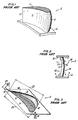
- Figures 1-3 show a prior art stator vane 2 for forming a varying nozzle throat with respect to radial displacement along the vane span.
- Figure 1 shows such a prior art vane 2 having an airfoil body 10 with a curved span leading edge 12 and a substantially linear trailing edge 14.
- the airfoil body 10 is secured at the radially inward end to a platform 16.
- the radially outward airfoil body end is also typically secured to a similar transversely extending member which is not shown here for clarity.
- Figure 1 The perspective view of Figure 1 may best be appreciated with reference to Figure 3 which shows a radially inward looking view of the prior art vane 2.
- the airfoil body 10 is shown having a cross section noted by reference numeral 18 at the radially inward and radially outward ends thereof, and a cross section denoted 20 at or near the body midspan.
- the suction side 36 is thus displaced circumferentially along the radial span of the vane 2, thereby achieving the varying throat size in conjunction with circumferentially adjacent vanes (not shown).
- the airfoil body 10 of the prior art vane 2 as shown in Figure 3 thus defines a constant chord length over the vane span as denoted by dimensions 22, 24.
- the curvature of the airfoil span causes a variation of the trailing edge angles 26, 28 in addition to the varying nozzle throat.
- the result of the varying throat size and trailing edge angle in the prior art vanes is the realization of an optimum axial gas velocity profile at the vane stage exit plane. As noted above, however, this optimum profile has been found to deteriorate rapidly between the vane stage exit and the adjacent, downstream rotor inlet.
- FIG. 4 shows a perspective view of the stator vane 4 according to the present invention.
- the vane 4 includes an airfoil body 38 extending spanwisely across an annularly flowing stream of working fluid (not shown) and being secured at the radially inner, or root, end 40 to a platform 42 as shown in the Figure.
- the radially outer, or tip, end 44 is also secured to an outer platform or other structure (not shown) forming the radially outward cylindrical boundary of the annular working fluid flow stream.
- the airfoil body includes a leading edge 46 and a trailing edge 48, and defines a plurality of airfoil cross sections shown representatively at the radially inner and outer ends 40, 44 and at the vane midspan 50.
- chordal dimension 52, 54 over the span of the airfoil body 38 results in a variation of the stator vane throat size as defined between two circumferentially adjacent vanes 4, 4a configured according to the present invention.
- the nozzle throat 56 defined at the vane outer end 44 is larger than the nozzle throat 58 defined at the blade midspan.
- the magnitude of the nozzle exit angle 60 measured at the trailing edge of the vane tip 44 is less than that of the exit angle 62 measured at the vane midspan 50.
- the vane configuration according to the present invention thus increases the axial velocity component of the working fluid adjacent the radially inward and outward portions of the annular working fluid stream by reducing the nozzle throat in the vane midspan and increasing working fluid mass flow adjacent the annulus boundaries.
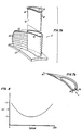
- Figures 6a and 6b represent experimental and computational data supporting the effectiveness of the vane configuration according to the present invention.
- Figures 6a, 6b show axial velocity, V x′ plotted vertically against percent vane span on the horizontal axis. Zero percent span corresponds to the radially inner end 40 of the vane while 100 percent span corresponds to the radially outer end 44.
- both the prior art vane 2 and the vane according to the present invention 4 provide similar respective axial gas velocity profiles 64, 66 at the gas exit plane of the respective stator vane stages.
- This optimal profile in the area of the inner and outer annular radii is achieved at least in part by the constant shape of the airfoil body 38 along the span of the blade 4.
- the upstream portion 68 of the vane 4 is substantially unchanged along the blade span, while the downstream portion 70 is altered dramatically.
- the suction side 72 of the vane airfoil body 38 also remains unchanged in shape even in the downstream portion 70 while the pressure side 74 is faired into the trailing edge 48 in order to accommodate the alteration in chordal dimension over the vane span.
- FIG. 7a Another advantage of the linear or straight span airfoil body configuration of the vane according to the present invention is illustrated in Figure 7a wherein the vane 4 according to the present invention is shown having an internal cooling cavity 76 extending spanwisely between the radially inner end 40 and the radially outer end 44.
- the cavity 76 is adapted for receiving an internal heat transfer augmentation structure 78 such as the impingement tube shown in the removed position in Figure 7a.
- the impingement tube 78 operates by receiving a flow of cooling gas 80, such as air, into the tube interior and directing it outward against the interior surface of the cavity 76 through a plurality of impingement openings 82.
- cooling air exiting the impingement openings 82 impacts the interior of the cavity 76 at relatively high velocity thus achieving a high rate of heat transfer between the vane material and a given flow of cooling gas.
- the cooling air 80 may exit the vane 4 either radially or through transpiration openings 84 shown typically in Figures 7a and 7b.
Landscapes
- Engineering & Computer Science (AREA)
- Mechanical Engineering (AREA)
- General Engineering & Computer Science (AREA)
- Physics & Mathematics (AREA)
- Fluid Mechanics (AREA)
- Turbine Rotor Nozzle Sealing (AREA)
Claims (3)
Applications Claiming Priority (2)
| Application Number | Priority Date | Filing Date | Title |
|---|---|---|---|
| US868397 | 1986-05-28 | ||
| US06/868,397 US4741667A (en) | 1986-05-28 | 1986-05-28 | Stator vane |
Publications (3)
| Publication Number | Publication Date |
|---|---|
| EP0251978A2 EP0251978A2 (de) | 1988-01-07 |
| EP0251978A3 EP0251978A3 (en) | 1989-05-24 |
| EP0251978B1 true EP0251978B1 (de) | 1991-05-02 |
Family
ID=25351592
Family Applications (1)
| Application Number | Title | Priority Date | Filing Date |
|---|---|---|---|
| EP87630098A Expired - Lifetime EP0251978B1 (de) | 1986-05-28 | 1987-05-26 | Statorschaufel |
Country Status (5)
| Country | Link |
|---|---|
| US (1) | US4741667A (de) |
| EP (1) | EP0251978B1 (de) |
| JP (1) | JPS62294704A (de) |
| CA (1) | CA1278522C (de) |
| DE (1) | DE3769714D1 (de) |
Families Citing this family (70)
| Publication number | Priority date | Publication date | Assignee | Title |
|---|---|---|---|---|
| US4889470A (en) * | 1988-08-01 | 1989-12-26 | Westinghouse Electric Corp. | Compressor diaphragm assembly |
| US5088892A (en) * | 1990-02-07 | 1992-02-18 | United Technologies Corporation | Bowed airfoil for the compression section of a rotary machine |
| US5281084A (en) * | 1990-07-13 | 1994-01-25 | General Electric Company | Curved film cooling holes for gas turbine engine vanes |
| US5211703A (en) * | 1990-10-24 | 1993-05-18 | Westinghouse Electric Corp. | Stationary blade design for L-OC row |
| DE4228879A1 (de) * | 1992-08-29 | 1994-03-03 | Asea Brown Boveri | Axialdurchströmte Turbine |
| US5326221A (en) * | 1993-08-27 | 1994-07-05 | General Electric Company | Over-cambered stage design for steam turbines |
| GB9417406D0 (en) * | 1994-08-30 | 1994-10-19 | Gec Alsthom Ltd | Turbine blade |
| US6375419B1 (en) | 1995-06-02 | 2002-04-23 | United Technologies Corporation | Flow directing element for a turbine engine |
| JPH10184304A (ja) * | 1996-12-27 | 1998-07-14 | Toshiba Corp | 軸流タービンのタービンノズルおよびタービン動翼 |
| US6195983B1 (en) | 1999-02-12 | 2001-03-06 | General Electric Company | Leaned and swept fan outlet guide vanes |
| GB0003676D0 (en) * | 2000-02-17 | 2000-04-05 | Abb Alstom Power Nv | Aerofoils |
| JP2002221006A (ja) * | 2001-01-25 | 2002-08-09 | Ishikawajima Harima Heavy Ind Co Ltd | タービンノズルのスロートエリア計測方法 |
| US6672832B2 (en) * | 2002-01-07 | 2004-01-06 | General Electric Company | Step-down turbine platform |
| GB2384276A (en) * | 2002-01-18 | 2003-07-23 | Alstom | Gas turbine low pressure stage |
| EP1582695A1 (de) * | 2004-03-26 | 2005-10-05 | Siemens Aktiengesellschaft | Schaufel für eine Strömungsmaschine |
| US7967571B2 (en) * | 2006-11-30 | 2011-06-28 | General Electric Company | Advanced booster rotor blade |
| US8292574B2 (en) | 2006-11-30 | 2012-10-23 | General Electric Company | Advanced booster system |
| US8087884B2 (en) * | 2006-11-30 | 2012-01-03 | General Electric Company | Advanced booster stator vane |
| JP4838733B2 (ja) * | 2007-01-12 | 2011-12-14 | 三菱重工業株式会社 | ガスタービンの翼構造 |
| US7740449B1 (en) | 2007-01-26 | 2010-06-22 | Florida Turbine Technologies, Inc. | Process for adjusting a flow capacity of an airfoil |
| GB0704426D0 (en) * | 2007-03-08 | 2007-04-18 | Rolls Royce Plc | Aerofoil members for a turbomachine |
| US20090016871A1 (en) * | 2007-07-10 | 2009-01-15 | United Technologies Corp. | Systems and Methods Involving Variable Vanes |
| US20090139236A1 (en) * | 2007-11-29 | 2009-06-04 | General Electric Company | Premixing device for enhanced flameholding and flash back resistance |
| US8197209B2 (en) * | 2007-12-19 | 2012-06-12 | United Technologies Corp. | Systems and methods involving variable throat area vanes |
| US8075259B2 (en) * | 2009-02-13 | 2011-12-13 | United Technologies Corporation | Turbine vane airfoil with turning flow and axial/circumferential trailing edge configuration |
| US10287987B2 (en) * | 2010-07-19 | 2019-05-14 | United Technologies Corporation | Noise reducing vane |
| WO2012053024A1 (ja) * | 2010-10-18 | 2012-04-26 | 株式会社 日立製作所 | 遷音速翼 |
| EP2476862B1 (de) * | 2011-01-13 | 2013-11-20 | Alstom Technology Ltd | Leitschaufel für eine axiale Strömungsmaschine und zugehörige Strömungsmaschine |
| US8967959B2 (en) * | 2011-10-28 | 2015-03-03 | General Electric Company | Turbine of a turbomachine |
| US8992179B2 (en) | 2011-10-28 | 2015-03-31 | General Electric Company | Turbine of a turbomachine |
| US9255480B2 (en) * | 2011-10-28 | 2016-02-09 | General Electric Company | Turbine of a turbomachine |
| US9051843B2 (en) | 2011-10-28 | 2015-06-09 | General Electric Company | Turbomachine blade including a squeeler pocket |
| ITTO20111009A1 (it) | 2011-11-03 | 2013-05-04 | Avio Spa | Profilo aerodinamico di una turbina |
| US9017037B2 (en) * | 2012-01-24 | 2015-04-28 | United Technologies Corporation | Rotor with flattened exit pressure profile |
| EP2620592A1 (de) * | 2012-01-26 | 2013-07-31 | Alstom Technology Ltd | Gasturbinentriebwerksschaufel mit einem rohrförmigen Prallkühlungselement |
| US8926289B2 (en) | 2012-03-08 | 2015-01-06 | Hamilton Sundstrand Corporation | Blade pocket design |
| US9157326B2 (en) * | 2012-07-02 | 2015-10-13 | United Technologies Corporation | Airfoil for improved flow distribution with high radial offset |
| US10184340B2 (en) * | 2013-03-15 | 2019-01-22 | United Technologies Corporation | Geared turbofan engine having a reduced number of fan blades and improved acoustics |
| EP3907374B1 (de) | 2013-08-21 | 2025-05-28 | RTX Corporation | Turbinenanordnung mit variabler fläche und sekundärströmungsmodulation |
| US10352180B2 (en) * | 2013-10-23 | 2019-07-16 | General Electric Company | Gas turbine nozzle trailing edge fillet |
| US9458732B2 (en) * | 2013-10-25 | 2016-10-04 | General Electric Company | Transition duct assembly with modified trailing edge in turbine system |
| WO2015175052A2 (en) | 2014-02-19 | 2015-11-19 | United Technologies Corporation | Gas turbine engine airfoil |
| EP3108123B1 (de) | 2014-02-19 | 2023-10-04 | Raytheon Technologies Corporation | Turboluftstrahltriebwerk mit getriebefan und niederdruckverdichterschaufeln |
| EP3108103B1 (de) | 2014-02-19 | 2023-09-27 | Raytheon Technologies Corporation | Fanschaufel für ein gastrubinentriebwerk |
| EP3108100B1 (de) | 2014-02-19 | 2021-04-14 | Raytheon Technologies Corporation | Gasturbinengebläseschaufel |
| US10570915B2 (en) | 2014-02-19 | 2020-02-25 | United Technologies Corporation | Gas turbine engine airfoil |
| US9140127B2 (en) | 2014-02-19 | 2015-09-22 | United Technologies Corporation | Gas turbine engine airfoil |
| EP3985226B1 (de) * | 2014-02-19 | 2024-12-25 | RTX Corporation | Gasturbinentriebwerk-schaufelprofil |
| WO2015175073A2 (en) | 2014-02-19 | 2015-11-19 | United Technologies Corporation | Gas turbine engine airfoil |
| US10570916B2 (en) | 2014-02-19 | 2020-02-25 | United Technologies Corporation | Gas turbine engine airfoil |
| WO2015175043A2 (en) | 2014-02-19 | 2015-11-19 | United Technologies Corporation | Gas turbine engine airfoil |
| EP3108105B1 (de) | 2014-02-19 | 2021-05-12 | Raytheon Technologies Corporation | Gasturbinenmotor-tragfläche |
| WO2015126941A1 (en) | 2014-02-19 | 2015-08-27 | United Technologies Corporation | Gas turbine engine airfoil |
| US10584715B2 (en) | 2014-02-19 | 2020-03-10 | United Technologies Corporation | Gas turbine engine airfoil |
| EP3108120B1 (de) | 2014-02-19 | 2021-03-31 | Raytheon Technologies Corporation | Gasturbinentriebwerk mit einer getriebearchitektur und einer spezifischen festen schaufelstruktur |
| EP3108106B1 (de) | 2014-02-19 | 2022-05-04 | Raytheon Technologies Corporation | Schaufelblatt eines gasturbinenmotors |
| EP3575551B1 (de) | 2014-02-19 | 2021-10-27 | Raytheon Technologies Corporation | Gasturbinenmotorschaufel |
| US10465702B2 (en) | 2014-02-19 | 2019-11-05 | United Technologies Corporation | Gas turbine engine airfoil |
| WO2015126454A1 (en) | 2014-02-19 | 2015-08-27 | United Technologies Corporation | Gas turbine engine airfoil |
| EP3108101B1 (de) | 2014-02-19 | 2022-04-20 | Raytheon Technologies Corporation | Gasturbinenmotor-tragfläche |
| US10495106B2 (en) | 2014-02-19 | 2019-12-03 | United Technologies Corporation | Gas turbine engine airfoil |
| WO2015175044A2 (en) | 2014-02-19 | 2015-11-19 | United Technologies Corporation | Gas turbine engine airfoil |
| US9567858B2 (en) | 2014-02-19 | 2017-02-14 | United Technologies Corporation | Gas turbine engine airfoil |
| US9611744B2 (en) | 2014-04-04 | 2017-04-04 | Betty Jean Taylor | Intercooled compressor for a gas turbine engine |
| US11248622B2 (en) * | 2016-09-02 | 2022-02-15 | Raytheon Technologies Corporation | Repeating airfoil tip strong pressure profile |
| FR3070448B1 (fr) * | 2017-08-28 | 2019-09-06 | Safran Aircraft Engines | Aube de redresseur de soufflante de turbomachine, ensemble de turbomachine comprenant une telle aube et turbomachine equipee de ladite aube ou dudit ensemble |
| US12553348B2 (en) * | 2018-11-09 | 2026-02-17 | Rtx Corporation | Airfoil with arced baffle |
| JP7029181B2 (ja) * | 2019-04-22 | 2022-03-03 | 株式会社アテクト | ノズルベーン |
| DE102019210693A1 (de) | 2019-07-19 | 2021-01-21 | MTU Aero Engines AG | Laufschaufel für eine strömungsmaschine |
| CN110617117B (zh) * | 2019-08-02 | 2022-04-08 | 中国航发贵阳发动机设计研究所 | 一种涡轮导向器喉道面积调节方法 |
Citations (1)
| Publication number | Priority date | Publication date | Assignee | Title |
|---|---|---|---|---|
| DE672789C (de) * | 1936-04-22 | 1939-03-10 | Aeg | Hochdruckdampfturbinenschaufel |
Family Cites Families (11)
| Publication number | Priority date | Publication date | Assignee | Title |
|---|---|---|---|---|
| CH171763A (de) * | 1932-11-15 | 1934-09-15 | Provincial Incandescent Fittin | Elektrischer Strom- und Spannungsmesser für mehrere Messbereiche. |
| DE672989C (de) * | 1935-12-24 | 1939-03-15 | Mij Voor Zwavelzuurbereiding V | Verfahren zum Gewinnen oder Entfernen von Metallen mit niedrigerer Verbrennungswaerme als der des Eisens |
| CH218193A (de) * | 1940-12-07 | 1941-11-30 | Oerlikon Maschf | Turbinen-Schaufelung, insbesondere für Gasturbinen. |
| US2801790A (en) * | 1950-06-21 | 1957-08-06 | United Aircraft Corp | Compressor blading |
| GB719061A (en) * | 1950-06-21 | 1954-11-24 | United Aircraft Corp | Blade arrangement for improving the performance of a gas turbine plant |
| US2746672A (en) * | 1950-07-27 | 1956-05-22 | United Aircraft Corp | Compressor blading |
| FR1110068A (fr) * | 1953-10-22 | 1956-02-06 | Maschf Augsburg Nuernberg Ag | Aube directrice pour machines à circulation axiale |
| BE570267A (de) * | 1957-08-16 | |||
| GB916672A (en) * | 1959-12-23 | 1963-01-23 | Prvni Brnenska Strojirna Zd Y | Improvements in and relating to exhaust gas turbines |
| DE2034890A1 (de) * | 1969-07-21 | 1971-02-04 | Rolls Royce Ltd Derby, Derbyshire (Großbritannien) | Schaufel fur Axialstromungsmaschinen |
| GB2129882B (en) * | 1982-11-10 | 1986-04-16 | Rolls Royce | Gas turbine stator vane |
-
1986
- 1986-05-28 US US06/868,397 patent/US4741667A/en not_active Expired - Fee Related
-
1987
- 1987-05-07 CA CA000536631A patent/CA1278522C/en not_active Expired - Lifetime
- 1987-05-26 EP EP87630098A patent/EP0251978B1/de not_active Expired - Lifetime
- 1987-05-26 DE DE8787630098T patent/DE3769714D1/de not_active Expired - Lifetime
- 1987-05-28 JP JP62133245A patent/JPS62294704A/ja active Pending
Patent Citations (1)
| Publication number | Priority date | Publication date | Assignee | Title |
|---|---|---|---|---|
| DE672789C (de) * | 1936-04-22 | 1939-03-10 | Aeg | Hochdruckdampfturbinenschaufel |
Also Published As
| Publication number | Publication date |
|---|---|
| EP0251978A3 (en) | 1989-05-24 |
| JPS62294704A (ja) | 1987-12-22 |
| DE3769714D1 (de) | 1991-06-06 |
| CA1278522C (en) | 1991-01-02 |
| EP0251978A2 (de) | 1988-01-07 |
| US4741667A (en) | 1988-05-03 |
Similar Documents
| Publication | Publication Date | Title |
|---|---|---|
| EP0251978B1 (de) | Statorschaufel | |
| EP1259711B1 (de) | Schaufel für eine axial durchströmte turbomaschine | |
| EP1731712B1 (de) | Turbinenschaufel mit variablem und zusammengesetztem Schaufel/Deckbandübergangsbereich | |
| JP4063937B2 (ja) | ガスタービンエンジン内の翼の冷却通路の乱流促進構造 | |
| US8647054B2 (en) | Axial turbo engine with low gap losses | |
| EP3608505B1 (de) | Turbine mit seitenwandführung | |
| EP0942150B1 (de) | Leitschaufelanordnung für eine Turbomaschine | |
| EP0654585B1 (de) | Geometrie einer Turbomaschinenschaufel | |
| US8858159B2 (en) | Gas turbine engine component having wavy cooling channels with pedestals | |
| US5468125A (en) | Turbine blade with improved heat transfer surface | |
| JP4311919B2 (ja) | ガスタービンエンジン用のタービン翼形部 | |
| EP0704602A2 (de) | Turbinenschaufel | |
| JPH04262002A (ja) | 蒸気タービンの静翼構造 | |
| EP3436668A1 (de) | Turbinenschaufel mit verwirbelungsfunktion an einer kalten wand | |
| WO2013133945A1 (en) | Airfoil with improved internal cooling channel pedestals | |
| JP4245873B2 (ja) | ガスタービンエンジン用のタービン翼形部 | |
| US5035578A (en) | Blading for reaction turbine blade row | |
| US20170211393A1 (en) | Gas turbine aerofoil trailing edge | |
| JP2684936B2 (ja) | ガスタービン及びガスタービン翼 | |
| CN205532726U (zh) | 涡轮叶片中的内部冷却通道 | |
| JP2015127541A (ja) | タービンブレード内の構造構成および冷却回路 | |
| US20170145958A1 (en) | Gas turbine engine | |
| US12270317B2 (en) | Airfoils for gas turbine engines | |
| EP3425165B1 (de) | Mechanische komponente | |
| RU2857659C1 (ru) | Форма лопасти вентилятора ТВРД |
Legal Events
| Date | Code | Title | Description |
|---|---|---|---|
| PUAI | Public reference made under article 153(3) epc to a published international application that has entered the european phase |
Free format text: ORIGINAL CODE: 0009012 |
|
| AK | Designated contracting states |
Kind code of ref document: A2 Designated state(s): DE FR GB |
|
| PUAL | Search report despatched |
Free format text: ORIGINAL CODE: 0009013 |
|
| AK | Designated contracting states |
Kind code of ref document: A3 Designated state(s): DE FR GB |
|
| 17P | Request for examination filed |
Effective date: 19890704 |
|
| 17Q | First examination report despatched |
Effective date: 19891010 |
|
| GRAA | (expected) grant |
Free format text: ORIGINAL CODE: 0009210 |
|
| PGFP | Annual fee paid to national office [announced via postgrant information from national office to epo] |
Ref country code: FR Payment date: 19910416 Year of fee payment: 5 |
|
| PGFP | Annual fee paid to national office [announced via postgrant information from national office to epo] |
Ref country code: DE Payment date: 19910418 Year of fee payment: 5 |
|
| AK | Designated contracting states |
Kind code of ref document: B1 Designated state(s): DE FR GB |
|
| PGFP | Annual fee paid to national office [announced via postgrant information from national office to epo] |
Ref country code: GB Payment date: 19910502 Year of fee payment: 5 |
|
| ET | Fr: translation filed | ||
| REF | Corresponds to: |
Ref document number: 3769714 Country of ref document: DE Date of ref document: 19910606 |
|
| PLBE | No opposition filed within time limit |
Free format text: ORIGINAL CODE: 0009261 |
|
| STAA | Information on the status of an ep patent application or granted ep patent |
Free format text: STATUS: NO OPPOSITION FILED WITHIN TIME LIMIT |
|
| 26N | No opposition filed | ||
| PG25 | Lapsed in a contracting state [announced via postgrant information from national office to epo] |
Ref country code: GB Effective date: 19920526 |
|
| GBPC | Gb: european patent ceased through non-payment of renewal fee |
Effective date: 19920526 |
|
| PG25 | Lapsed in a contracting state [announced via postgrant information from national office to epo] |
Ref country code: FR Effective date: 19930129 |
|
| PG25 | Lapsed in a contracting state [announced via postgrant information from national office to epo] |
Ref country code: DE Effective date: 19930202 |
|
| REG | Reference to a national code |
Ref country code: FR Ref legal event code: ST |