EP0252184A1 - Lecture d'un compteur à travers le couvercle d'une fosse - Google Patents
Lecture d'un compteur à travers le couvercle d'une fosse Download PDFInfo
- Publication number
- EP0252184A1 EP0252184A1 EP86115258A EP86115258A EP0252184A1 EP 0252184 A1 EP0252184 A1 EP 0252184A1 EP 86115258 A EP86115258 A EP 86115258A EP 86115258 A EP86115258 A EP 86115258A EP 0252184 A1 EP0252184 A1 EP 0252184A1
- Authority
- EP
- European Patent Office
- Prior art keywords
- sensor
- meter
- face plate
- wall
- enclosure
- Prior art date
- Legal status (The legal status is an assumption and is not a legal conclusion. Google has not performed a legal analysis and makes no representation as to the accuracy of the status listed.)
- Withdrawn
Links
Images
Classifications
-
- G—PHYSICS
- G08—SIGNALLING
- G08C—TRANSMISSION SYSTEMS FOR MEASURED VALUES, CONTROL OR SIMILAR SIGNALS
- G08C17/00—Arrangements for transmitting signals characterised by the use of a wireless electrical link
- G08C17/04—Arrangements for transmitting signals characterised by the use of a wireless electrical link using magnetically coupled devices
-
- H—ELECTRICITY
- H04—ELECTRIC COMMUNICATION TECHNIQUE
- H04B—TRANSMISSION
- H04B5/00—Near-field transmission systems, e.g. inductive or capacitive transmission systems
- H04B5/20—Near-field transmission systems, e.g. inductive or capacitive transmission systems characterised by the transmission technique; characterised by the transmission medium
- H04B5/24—Inductive coupling
- H04B5/26—Inductive coupling using coils
- H04B5/266—One coil at each side, e.g. with primary and secondary coils
-
- G—PHYSICS
- G01—MEASURING; TESTING
- G01D—MEASURING NOT SPECIALLY ADAPTED FOR A SPECIFIC VARIABLE; ARRANGEMENTS FOR MEASURING TWO OR MORE VARIABLES NOT COVERED IN A SINGLE OTHER SUBCLASS; TARIFF METERING APPARATUS; MEASURING OR TESTING NOT OTHERWISE PROVIDED FOR
- G01D4/00—Tariff metering apparatus
- G01D4/002—Remote reading of utility meters
- G01D4/006—Remote reading of utility meters to a non-fixed location, i.e. mobile location
-
- H—ELECTRICITY
- H04—ELECTRIC COMMUNICATION TECHNIQUE
- H04B—TRANSMISSION
- H04B5/00—Near-field transmission systems, e.g. inductive or capacitive transmission systems
- H04B5/70—Near-field transmission systems, e.g. inductive or capacitive transmission systems specially adapted for specific purposes
- H04B5/73—Near-field transmission systems, e.g. inductive or capacitive transmission systems specially adapted for specific purposes for taking measurements, e.g. using sensing coils
-
- H—ELECTRICITY
- H04—ELECTRIC COMMUNICATION TECHNIQUE
- H04B—TRANSMISSION
- H04B5/00—Near-field transmission systems, e.g. inductive or capacitive transmission systems
- H04B5/70—Near-field transmission systems, e.g. inductive or capacitive transmission systems specially adapted for specific purposes
- H04B5/77—Near-field transmission systems, e.g. inductive or capacitive transmission systems specially adapted for specific purposes for interrogation
-
- Y—GENERAL TAGGING OF NEW TECHNOLOGICAL DEVELOPMENTS; GENERAL TAGGING OF CROSS-SECTIONAL TECHNOLOGIES SPANNING OVER SEVERAL SECTIONS OF THE IPC; TECHNICAL SUBJECTS COVERED BY FORMER USPC CROSS-REFERENCE ART COLLECTIONS [XRACs] AND DIGESTS
- Y02—TECHNOLOGIES OR APPLICATIONS FOR MITIGATION OR ADAPTATION AGAINST CLIMATE CHANGE
- Y02B—CLIMATE CHANGE MITIGATION TECHNOLOGIES RELATED TO BUILDINGS, e.g. HOUSING, HOUSE APPLIANCES OR RELATED END-USER APPLICATIONS
- Y02B90/00—Enabling technologies or technologies with a potential or indirect contribution to GHG emissions mitigation
- Y02B90/20—Smart grids as enabling technology in buildings sector
-
- Y—GENERAL TAGGING OF NEW TECHNOLOGICAL DEVELOPMENTS; GENERAL TAGGING OF CROSS-SECTIONAL TECHNOLOGIES SPANNING OVER SEVERAL SECTIONS OF THE IPC; TECHNICAL SUBJECTS COVERED BY FORMER USPC CROSS-REFERENCE ART COLLECTIONS [XRACs] AND DIGESTS
- Y04—INFORMATION OR COMMUNICATION TECHNOLOGIES HAVING AN IMPACT ON OTHER TECHNOLOGY AREAS
- Y04S—SYSTEMS INTEGRATING TECHNOLOGIES RELATED TO POWER NETWORK OPERATION, COMMUNICATION OR INFORMATION TECHNOLOGIES FOR IMPROVING THE ELECTRICAL POWER GENERATION, TRANSMISSION, DISTRIBUTION, MANAGEMENT OR USAGE, i.e. SMART GRIDS
- Y04S20/00—Management or operation of end-user stationary applications or the last stages of power distribution; Controlling, monitoring or operating thereof
- Y04S20/30—Smart metering, e.g. specially adapted for remote reading
Definitions
- This invention relates to the reading of utility meters which are located outside of the residence in pits below the surface of the ground.
- a long standing problem in the utility industry is the economic reading of utility meters without inconvenience to the home owner.
- the problem is especially acute in connection with the reading of water meters.
- the reading of such meter installations presents a number of problems in that it may cause inconvenience to the homeowner, or the homeowner may be absent at the time the individual taking meter readings is making his rounds making it necessary to subsequently revisit such residences, or delay taking the reading until the next regularly scheduled visit or request the homeowner to take the reading visually and send it to the utility on forms provided by the utility.
- Another approach to the problem has been to provide the meter within the residence with an encoded register with storage means in which data representative of volumetric flow through the meter is accumulated.
- the output from the encoded register is then connected to a receptacle located outside of the building.
- a readout device is carried by the person taking the reading and by plugging the readout device into the receptacle thereby connecting the readout device with the output of the encoded register so that the data stored in the register is downloaded into the readout device.
- An interrogation signal is sent by the portable interrogator/storage unit through the inductively coupled coils to the encoded register at the meter, which in response to the interrogation signal transmits the data accumulated by the encoder through the inductive coupling into the portable interrogator/storage unit.
- the system described immediately above has the advantage of economical and error-free recording of data accumulated by the meter encoder.
- the entire meter is located outside of the residence within a pit below the surface of the ground.
- it is current practice to locate the meter sensor unit on the meter itself which of course is below the level of the ground within the pit.
- the individual taking the reading is equipped with an interrogator/storage unit and a portable sensor as described above but which in such cases would be located at the end of an extension rod.
- the individual taking the reading then removes the pit cover and extends the portable sensor into the pit until it is in close enough proximity with the sensor on the meter to establish an inductive coupling between the two coils located respectively within the meter sensor and the portable sensor.
- Such an arrangement is shown in Bulletin W-1500 published by the Municipal and Control Division of the Rockwell International Corporation.
- Applicants have devised a meter reading system in which the meter sensor is located in the cover of the pit in which the meter itself is installed.
- the individual performing the reading operation then carries a portable interrogator/storage unit and the portable sensor is located at the end of an extension rod.
- the portable interrogator sensor then is brought into close proximity to the meter sensor located on the pit cover in order to achieve an inductive coupling between the two coils located respectively in the two sensors whereby data accumulated in the encoded register at the meter may be transmitted from the register via the two sensors into the interrogator/storage unit where it is stored until downloaded by equipment installed at the utilities premises.
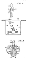
- Figure 1 shows an underground chamber or pit 10 the walls and floor 12 of which are formed of some suitable material such as masonry.
- a water meter 14 is installed together with an encoded register 16 driven by the flow responsive element within the meter 14.
- the encoded register 16 is comprised of a water tight housing which encloses several digit wheels driven by the meter flow responsive element to indicate the volume of water having flowed through the meter. The position of each digit wheel is sensed by suitable electric circuitry such as that as described in co-pending application for U. S. patent of Bruce Gray, Serial No. 510,753 filed July 1, 1983.
- register 16 The output of register 16 is electrically connected by means of a waterproof cord 18 to a meter sensor designated generally by the numeral 20 located in the pit cover 22 which is removable or hinged to the top of the pit.
- the sensor assembly 20 is comprised of a housing 30 which in turn is comprised of a face plate 32 which has a downwardly extending tubular extension 34.
- the tubular extension 34 has an exterior threaded section 36 and projects through an opening 38 in the pit cover 22.
- a locking nut 40 is threaded onto the threaded section 36 from the inside of the cover 22 so as to clamp the portion of the cover 22 surrounding the opening 38 between face plate 32 and locking nut 40.
- a passage 44 extends axially through housing 30 and an annular shoulder 42 is formed in the face plate 32 around the upper end of the passage 44.
- the meter sensor 46 is received within the passage 44 so that its upper end abuts against shoulder 42 in face plate 32 when in place in the assembly.
- the passage 44 is internally threaded to receive a threaded tube 52 to clamp the sensor 46 between shoulder 42 in face plate 32 and the end of the tube 52.
- a circular recess 54 is formed in the upper surface of face plate 32 by uniformly spaced radially extending sloping raised portions 56.
- the sensor 46 contains an inductive coil sealed within the sensor which is electrically connected to the register 16 (Fig. 1) by means of cord 18.
- an interrogator sensor 60 is contained within a housing 62 which is mounted on the end of extension 66 by means of a universal joint 64 to facilitate alignment of housing 62 in recess 54.
- housing 62 is fully inserted into recess 54 the sensors 46 and 60 will be inductively coupled.
- the housing 62 is of a size to snugly fit into recess 54 to thereby guide the sensor 60 into a good inductive coupling with sensor 46.
- the extension rod 66 is carried by an individual 68 who takes the meter reading.
- the individual also carries an interrogator/storage unit 70 which is connected by suitable wiring 72 extending through extension 66 to the coil within the sensor 60.
- the individual 68 In order to read the data accumulated by the encoded register 16, the individual 68 merely inserts the housing 62 into the recess 54. He then operates a switch on the handle 65 of the upper end of extension 66 to cause an interrogation signal to be sent through the sensor 60 and sensor 46 to the encoded register 16. Upon receipt of the interrogation signal the encoded register causes a signal to be sent back through sensors 46 and 60 to the interrogation/storage unit 70 which signal contains an identification of the particular meter being interrogated and digital data representative of the volumetric flow through the meter accumulated by the register.
Landscapes
- Engineering & Computer Science (AREA)
- Computer Networks & Wireless Communication (AREA)
- Physics & Mathematics (AREA)
- General Physics & Mathematics (AREA)
- Signal Processing (AREA)
- Arrangements For Transmission Of Measured Signals (AREA)
- Details Of Flowmeters (AREA)
Applications Claiming Priority (2)
| Application Number | Priority Date | Filing Date | Title |
|---|---|---|---|
| US87104386A | 1986-06-05 | 1986-06-05 | |
| US871043 | 1986-06-05 |
Publications (1)
| Publication Number | Publication Date |
|---|---|
| EP0252184A1 true EP0252184A1 (fr) | 1988-01-13 |
Family
ID=25356595
Family Applications (1)
| Application Number | Title | Priority Date | Filing Date |
|---|---|---|---|
| EP86115258A Withdrawn EP0252184A1 (fr) | 1986-06-05 | 1986-11-04 | Lecture d'un compteur à travers le couvercle d'une fosse |
Country Status (4)
| Country | Link |
|---|---|
| EP (1) | EP0252184A1 (fr) |
| JP (1) | JPS62287400A (fr) |
| DE (1) | DE252184T1 (fr) |
| ES (1) | ES2001153A4 (fr) |
Cited By (12)
| Publication number | Priority date | Publication date | Assignee | Title |
|---|---|---|---|---|
| FR2639107A1 (fr) * | 1988-11-14 | 1990-05-18 | Pont A Mousson | Procede et dispositif pour detecter l'etat d'une vanne |
| EP0380727A1 (fr) * | 1989-02-01 | 1990-08-08 | Megatone Ltd. | Appareil de distraction ou d'éducation produisant des sons |
| US5298894A (en) * | 1992-06-17 | 1994-03-29 | Badger Meter, Inc. | Utility meter transponder/antenna assembly for underground installations |
| WO1994022238A1 (fr) * | 1993-03-18 | 1994-09-29 | Thames Water Utilities Limited | Transmission de donnees |
| US5825303A (en) * | 1996-08-30 | 1998-10-20 | Badger Meter, Inc. | Sealed housing and method of sealing for apparatus in meter pit enclosures |
| US6218995B1 (en) | 1997-06-13 | 2001-04-17 | Itron, Inc. | Telemetry antenna system |
| US6262685B1 (en) | 1997-10-24 | 2001-07-17 | Itron, Inc. | Passive radiator |
| FR2841066A1 (fr) * | 2002-06-14 | 2003-12-19 | Michaud Sa | Dispositif de transmission d'informations a couplage magnetique |
| WO2006110362A3 (fr) * | 2005-04-08 | 2007-01-18 | M & Fc Holding Llc | Port de communications inductif destine a un dispositif de communication de lecture de compteur automatique |
| US7446672B2 (en) | 2005-03-24 | 2008-11-04 | M&Fc Holding, Llc | Method and apparatus for coupling a meter register to an automatic meter reading communication device |
| US8223034B2 (en) | 2009-09-11 | 2012-07-17 | Eister AMCO Water, LLC | Horizontal pit mount interface device |
| US8378847B2 (en) | 2009-09-11 | 2013-02-19 | Elster Amco Water, Llc | Pit mount interface device |
Families Citing this family (2)
| Publication number | Priority date | Publication date | Assignee | Title |
|---|---|---|---|---|
| JPH0799558B2 (ja) * | 1990-07-25 | 1995-10-25 | 柏原計器工業株式会社 | 流量検針装置 |
| JP2006236074A (ja) * | 2005-02-25 | 2006-09-07 | Toshiba Corp | 検針装置、無線タグ検針システム及び検針方法 |
Citations (6)
| Publication number | Priority date | Publication date | Assignee | Title |
|---|---|---|---|---|
| US3549985A (en) * | 1969-02-27 | 1970-12-22 | Electronic Sensing Prod Inc | Metal detecting device having a diskshaped head for housing a coil system |
| DE2732626A1 (de) * | 1976-08-08 | 1978-02-09 | Nippon Soken | Verbindungsvorrichtung zur uebertragung logischer signale |
| EP0011991A1 (fr) * | 1978-11-23 | 1980-06-11 | E. Allman & Company Limited | Perfectionnements relatifs à des dispositifs de commande à distance |
| US4463354A (en) * | 1981-12-09 | 1984-07-31 | Sears Lawrence M | Apparatus for communicating utility usage related information from a utility usage location to a portable utility usage registering device |
| EP0131732A2 (fr) * | 1983-06-20 | 1985-01-23 | M & FC HOLDING COMPANY, INC. | Système de couplage inductif pour la transmission bidirectionnelle de données numériques |
| US4500881A (en) * | 1982-09-23 | 1985-02-19 | Liquidometer Corporation | Inductively-coupled signalling system |
Family Cites Families (2)
| Publication number | Priority date | Publication date | Assignee | Title |
|---|---|---|---|---|
| JPS6037831U (ja) * | 1983-08-24 | 1985-03-15 | 横須賀市 | 穴内設置計測装置 |
| JPS60104999U (ja) * | 1983-12-16 | 1985-07-17 | 愛知時計電機株式会社 | 受信報知隔測装置 |
-
1986
- 1986-11-04 ES ES86115258T patent/ES2001153A4/es active Pending
- 1986-11-04 DE DE198686115258T patent/DE252184T1/de active Pending
- 1986-11-04 EP EP86115258A patent/EP0252184A1/fr not_active Withdrawn
- 1986-12-01 JP JP61286564A patent/JPS62287400A/ja active Granted
Patent Citations (6)
| Publication number | Priority date | Publication date | Assignee | Title |
|---|---|---|---|---|
| US3549985A (en) * | 1969-02-27 | 1970-12-22 | Electronic Sensing Prod Inc | Metal detecting device having a diskshaped head for housing a coil system |
| DE2732626A1 (de) * | 1976-08-08 | 1978-02-09 | Nippon Soken | Verbindungsvorrichtung zur uebertragung logischer signale |
| EP0011991A1 (fr) * | 1978-11-23 | 1980-06-11 | E. Allman & Company Limited | Perfectionnements relatifs à des dispositifs de commande à distance |
| US4463354A (en) * | 1981-12-09 | 1984-07-31 | Sears Lawrence M | Apparatus for communicating utility usage related information from a utility usage location to a portable utility usage registering device |
| US4500881A (en) * | 1982-09-23 | 1985-02-19 | Liquidometer Corporation | Inductively-coupled signalling system |
| EP0131732A2 (fr) * | 1983-06-20 | 1985-01-23 | M & FC HOLDING COMPANY, INC. | Système de couplage inductif pour la transmission bidirectionnelle de données numériques |
Cited By (16)
| Publication number | Priority date | Publication date | Assignee | Title |
|---|---|---|---|---|
| FR2639107A1 (fr) * | 1988-11-14 | 1990-05-18 | Pont A Mousson | Procede et dispositif pour detecter l'etat d'une vanne |
| EP0369918A1 (fr) * | 1988-11-14 | 1990-05-23 | Pont-A-Mousson S.A. | Procédé et dispositif pour détecter l'état d'une vanne |
| EP0380727A1 (fr) * | 1989-02-01 | 1990-08-08 | Megatone Ltd. | Appareil de distraction ou d'éducation produisant des sons |
| US5298894A (en) * | 1992-06-17 | 1994-03-29 | Badger Meter, Inc. | Utility meter transponder/antenna assembly for underground installations |
| WO1994022238A1 (fr) * | 1993-03-18 | 1994-09-29 | Thames Water Utilities Limited | Transmission de donnees |
| GB2291566A (en) * | 1993-03-18 | 1996-01-24 | Thames Water Utilities | Data transmission |
| GB2291566B (en) * | 1993-03-18 | 1996-09-11 | Thames Water Utilities | Data transmission |
| US5825303A (en) * | 1996-08-30 | 1998-10-20 | Badger Meter, Inc. | Sealed housing and method of sealing for apparatus in meter pit enclosures |
| US6218995B1 (en) | 1997-06-13 | 2001-04-17 | Itron, Inc. | Telemetry antenna system |
| US6262685B1 (en) | 1997-10-24 | 2001-07-17 | Itron, Inc. | Passive radiator |
| FR2841066A1 (fr) * | 2002-06-14 | 2003-12-19 | Michaud Sa | Dispositif de transmission d'informations a couplage magnetique |
| US7446672B2 (en) | 2005-03-24 | 2008-11-04 | M&Fc Holding, Llc | Method and apparatus for coupling a meter register to an automatic meter reading communication device |
| WO2006110362A3 (fr) * | 2005-04-08 | 2007-01-18 | M & Fc Holding Llc | Port de communications inductif destine a un dispositif de communication de lecture de compteur automatique |
| US7221286B2 (en) * | 2005-04-08 | 2007-05-22 | M&Fc Holding, Llc | Inductive communications port for an automatic meter reading communication device |
| US8223034B2 (en) | 2009-09-11 | 2012-07-17 | Eister AMCO Water, LLC | Horizontal pit mount interface device |
| US8378847B2 (en) | 2009-09-11 | 2013-02-19 | Elster Amco Water, Llc | Pit mount interface device |
Also Published As
| Publication number | Publication date |
|---|---|
| DE252184T1 (de) | 1988-07-21 |
| JPS62287400A (ja) | 1987-12-14 |
| ES2001153A4 (es) | 1988-05-01 |
| JPH0548520B2 (fr) | 1993-07-21 |
Similar Documents
| Publication | Publication Date | Title |
|---|---|---|
| EP0252184A1 (fr) | Lecture d'un compteur à travers le couvercle d'une fosse | |
| US7446672B2 (en) | Method and apparatus for coupling a meter register to an automatic meter reading communication device | |
| US6369769B1 (en) | Flush mounted pit lid antenna | |
| CA2091551C (fr) | Groupe transpondeur-antenne pour compteur d'installation souterraine | |
| US4888706A (en) | Fluid distribution to multiple users through distributed intelligence sub-centers | |
| US4901007A (en) | Portable electrical energy monitor | |
| US4523460A (en) | Fluid measuring, testing and accounting system | |
| US4729106A (en) | Fluid distribution to multiple users through distributed intelligence sub-centers | |
| AU651582B2 (en) | Two and three wire utility data communications system | |
| KR102008089B1 (ko) | 스마트미터링 기반 온도센서를 내장한 무선통신 단말 시스템 및 그 구동방법 | |
| EP1866605B1 (fr) | Port de communications inductif destine a un dispositif de communication de lecture de compteur automatique | |
| US6954144B1 (en) | Water pit transmitter assembly | |
| CZ167491A3 (en) | Self-contained system for detection and recording pulses | |
| JP2008516234A (ja) | パイプライン網内の振動の追跡 | |
| RU2077735C1 (ru) | Система информационного обеспечения разработки нефтяных месторождений | |
| KR20190139576A (ko) | 스마트미터링 기반 침수센서 및 잠금장치와 연동하는 무선통신 단말 시스템 및 그 구동방법 | |
| JPS56123383A (en) | Information transmission system for controlling corrosion prevention | |
| US4421417A (en) | Fluid delivery monitor | |
| EP1215471B1 (fr) | Détecteur de niveau de fluide | |
| US6748802B1 (en) | Universal mounting bracket for coupling a water meter to a data logger | |
| EP3824254B1 (fr) | Système, procédé et produit programme d'ordinateur permettant de réveiller un compteur d'eau | |
| JP2013178273A (ja) | パイプライン網内の振動の追跡 | |
| US7123163B2 (en) | System for measuring a parameter within a closed environment | |
| JPH0719927A (ja) | 発信器付流量メータ | |
| CN216559160U (zh) | 一种具有防电磁干扰功能的nb-iot远传水表 |
Legal Events
| Date | Code | Title | Description |
|---|---|---|---|
| PUAI | Public reference made under article 153(3) epc to a published international application that has entered the european phase |
Free format text: ORIGINAL CODE: 0009012 |
|
| AK | Designated contracting states |
Kind code of ref document: A1 Designated state(s): CH DE ES FR GB IT LI NL |
|
| ITCL | It: translation for ep claims filed |
Representative=s name: SOCIETA' ITALIANA BREVETTI S.P.A. |
|
| TCNL | Nl: translation of patent claims filed | ||
| EL | Fr: translation of claims filed | ||
| 17P | Request for examination filed |
Effective date: 19880203 |
|
| DET | De: translation of patent claims | ||
| RAP1 | Party data changed (applicant data changed or rights of an application transferred) |
Owner name: M & FC HOLDING COMPANY, INC. |
|
| STAA | Information on the status of an ep patent application or granted ep patent |
Free format text: STATUS: THE APPLICATION IS DEEMED TO BE WITHDRAWN |
|
| 18D | Application deemed to be withdrawn |
Effective date: 19900531 |
|
| RIN1 | Information on inventor provided before grant (corrected) |
Inventor name: SUTHERLAND, RAY Inventor name: PAINLEY, ELMER F. Inventor name: EDWARDS, JAMES F., JR. |