EP0252285A1 - Elektrischer Schalter - Google Patents
Elektrischer Schalter Download PDFInfo
- Publication number
- EP0252285A1 EP0252285A1 EP19870107957 EP87107957A EP0252285A1 EP 0252285 A1 EP0252285 A1 EP 0252285A1 EP 19870107957 EP19870107957 EP 19870107957 EP 87107957 A EP87107957 A EP 87107957A EP 0252285 A1 EP0252285 A1 EP 0252285A1
- Authority
- EP
- European Patent Office
- Prior art keywords
- contact member
- movable contact
- circuit breaker
- slider
- angle
- Prior art date
- Legal status (The legal status is an assumption and is not a legal conclusion. Google has not performed a legal analysis and makes no representation as to the accuracy of the status listed.)
- Withdrawn
Links
- 238000006073 displacement reaction Methods 0.000 claims abstract description 18
- 238000004140 cleaning Methods 0.000 description 12
- 230000000694 effects Effects 0.000 description 4
- 238000006243 chemical reaction Methods 0.000 description 2
- 238000010586 diagram Methods 0.000 description 2
- 229920000136 polysorbate Polymers 0.000 description 2
- 229910001369 Brass Inorganic materials 0.000 description 1
- 239000010951 brass Substances 0.000 description 1
- 238000013016 damping Methods 0.000 description 1
- 238000009434 installation Methods 0.000 description 1
- 210000003127 knee Anatomy 0.000 description 1
- 239000000463 material Substances 0.000 description 1
- 230000037361 pathway Effects 0.000 description 1
- 230000000717 retained effect Effects 0.000 description 1
- 238000005096 rolling process Methods 0.000 description 1
Images

Classifications
-
- H—ELECTRICITY
- H01—ELECTRIC ELEMENTS
- H01H—ELECTRIC SWITCHES; RELAYS; SELECTORS; EMERGENCY PROTECTIVE DEVICES
- H01H1/00—Contacts
- H01H1/12—Contacts characterised by the manner in which co-operating contacts engage
- H01H1/14—Contacts characterised by the manner in which co-operating contacts engage by abutting
- H01H1/18—Contacts characterised by the manner in which co-operating contacts engage by abutting with subsequent sliding
Definitions
- the present invention relates to an electric circuit breaker with a housing comprising a pair of fixed contact members or contact rails and a movable contact member with a first and a second, substantially parallel contact surface, said movable contact member being displaceable for establishing a connection between the two fixed contact members and with spring means for pressing the movable contact member against the fixed contact members in a closed position and where the movable contact member is attached to a slider movable on a guide track provided for this purpose and aligned with the spring means, said slider pressing the movable contact member into the open position when subjected to a pressure-transferring mechanism activated by the control handle of the circuit breaker and where the contact surfaces and the displacement direction of the guide track of the slider form an angle different from 90°.
- a circuit breaker which is characterised by the movable contact member comprising a first and a second midpart between, said first and second contact surfaces said first midpart being substantially perpendicular to the displacement direction of the slider and said second midpart being substantially parallel to the displacement direction of the slider.
- the movement of the movable contact member from the open to the closed position consists of two movements: First, the movable contact member is pressed by a spring in the displacement direction of the slider, said spring or springs being arranged perpendicular to the contact member, until the movable contact surfaces touch the fixed contact surfaces. Then the reaction forces of the fixed contact members oppose part of the spring pressure, resulting in a displacement force parallel to the contact surfaces. The resulting displacement force is proportional to the cosine of the angle between the contact surfaces and the direction of the spring forces and causes a displacement of the movable contact member parallel to the fixed contact surfaces, such that possible dirt is wiped off. Thus a self-cleaning effect is achieved.
- the guide track in the housing is arranged in such a way that the angle between the track and the bottom of the normally horizontally installed housing is approx. 10°, and such that the end of the slider actuating the movable contact member is closer to the bottom of the housing than the slider end subjected to the pressure-transferring mechanism, and the fixed and the movable contact surfaces form an angle of approx. 60° with said bottom.
- the corresponding known circuit breaker without self-cleaning contacts comprises a guide track, which is usually horizontal in the installation position, while contact surfaces and rails are normally vertical to this position.
- the circuit breaker housing furthermore comprises a retainer surface arranged such that a bend connecting the first and the second planar midparts of the contact member abuts the retainer surface in the closed position of the circuit breaker and when the breaker is opened, the bend or "knee" is guided back to its start position by the retainer surface.
- the retainer surface has two effects: First, the retainer surface stops the displacement of the movable contact member during the closing operation and thus defines its final position, second, the retainer surface is a guide surface for the movable contact member, when the latter is returned to its open position.
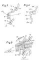
- the circuit breaker is shown in its preferred embodiment and comprises a housing 10, wherein a pair of fixed contacts 21 and 23 is mounted, which can be connected by a movable contact member 25.
- the movable contact member 25 is fastened between a strong spring 19, in the following referred to as toggle spring, and a somewhat weaker spring 31 inside a slider 27 sliding along a track 29 supported by guide points and guide grooves in the housing.
- Figure 1 shows furthermore that the toggle spring 19 is aligned with a track 29 and is at its base end guided and supported by a retainer wall 20.
- the circuit breaker is in Figure 1 shown in its closed position.
- a lever arm turning around a pivot 13 is actuated.
- the lever arm 11 is part of a partially circular holder 12 with a toggle arm 15, which can turn around the pivot 13 together with the lever arm 11.
- the toggle arm 15 is by means of a rotating joint 16 attached to one end of another arm 17, which is tapered being flat but rounded at the other end and is referred to in the following as toggle member 17.
- the toggle arm 15, the pivot 16 and the toggle member 17 constitute the pressure-transferring mechanism referred to in the introduction.
- the toggle member 17 protrudes into a V-shaped recess at one end of the slider 27, which moves in the track 29.
- the other end of the slider is provided with a track or groove, receiving the movable contact member 25.
- the movable contact member 25 is bent as shown in Figure 4 so that the contact member has two contact surfaces 25 a and 25 e at each end and a first planar midpart 25 b , approx. perpendicular to the other midpart 25 d with the two midparts meeting at the bend 25 c .
- the angle between the contact surface 25 a and the first midpart 25 b is between 130° and 150°, preferably 140°.
- the first midpart 25 b is, when mounted in the circuit breaker, approx. perpendicular to the slider and is guided in a track at the end surface of the slider.
- the movable contact member can be displaced in this track during the last part of the closing engagement, when the self-cleaning takes place.
- the first midpart 25 b is provided with a cam 38, which supports the adjacent end of the spring 19 so that the spring and the contact member 25 slip simultaneously, cleaning the contact surfaces.
- the bend 25 c abuts a retainer surface 33, which, as shown in the drawing, can be a continuation of the retainer wall 20. During the closing operation the retainer surface 33 stops the movable contact member and thus limits the travel x .
- the retainer surface 33 is preferably situated so that the angle between the retainer surface and the displacement direction of the slider defined by the track 29 is approx. 20°.
- the retainer surface 33 acts as a guiding surface for the bend 25 c when the movable contact member is pressed back into its start position.
- the movement of the movable contact member is thus triangular, as shown in Figure 5, where the first part of the closing operation is shown by the rectilinear movement 34 and the last part of the closing operation, i.e. the self-cleaning, is shown by the vector 35 with the length x .
- the movement follows the vector 36 defined by the retainer surface 33.
- the described embodiment of the circuit breaker possesses the additional advantage of a surprisingly short bounce time, which is presumably due to the sliding engagement combined with a dampening effect in the retainer wall and the contact member.
- An angle of approx. 80° between the first and the second midparts 25 b and 25 d of the contact member is found to be especially advantageous for achieving a short bounce time.
- the proposed new circuit breaker thus enables a controlled, well-defined travel exactly as long as is necessary for achieving a suitable cleaning of the contacts.
Landscapes
- Breakers (AREA)
Applications Claiming Priority (2)
| Application Number | Priority Date | Filing Date | Title |
|---|---|---|---|
| DK2608/86 | 1986-06-03 | ||
| DK260886A DK260886A (da) | 1986-06-03 | 1986-06-03 | Elektrisk afbryder |
Publications (1)
| Publication Number | Publication Date |
|---|---|
| EP0252285A1 true EP0252285A1 (de) | 1988-01-13 |
Family
ID=8113665
Family Applications (1)
| Application Number | Title | Priority Date | Filing Date |
|---|---|---|---|
| EP19870107957 Withdrawn EP0252285A1 (de) | 1986-06-03 | 1987-06-02 | Elektrischer Schalter |
Country Status (2)
| Country | Link |
|---|---|
| EP (1) | EP0252285A1 (de) |
| DK (1) | DK260886A (de) |
Cited By (3)
| Publication number | Priority date | Publication date | Assignee | Title |
|---|---|---|---|---|
| EP0515269A1 (de) * | 1991-05-22 | 1992-11-25 | Dav | Elektrischer Schnappschalter und aus mehreren Abteilen bestehende Schalteinheit |
| EP0576259A3 (en) * | 1992-06-24 | 1994-05-25 | Crabtree Electrical Ind Ltd | Electric switches |
| WO1999059177A1 (fr) * | 1998-05-14 | 1999-11-18 | Socomec S.A. | Appareil de coupure electrique pour installation electrique a basse tension alternative |
Citations (5)
| Publication number | Priority date | Publication date | Assignee | Title |
|---|---|---|---|---|
| DE2132658A1 (de) * | 1971-06-30 | 1973-01-18 | Marquardt J & J | Elektrischer schalter |
| DE2525467A1 (de) * | 1975-06-07 | 1976-12-16 | Calor Emag Elektrizitaets Ag | Kontaktanordnung |
| DE2817815A1 (de) * | 1978-04-22 | 1979-10-31 | Schaltbau Gmbh | Schnappschalter mit einer ueber einen stoessel betaetigten kontaktbruecke |
| EP0011413A1 (de) * | 1978-11-03 | 1980-05-28 | Bonnella Switches Limited | Schalter |
| EP0105817A1 (de) * | 1982-10-06 | 1984-04-18 | MANUFACTURE DES ALPES FRANCAISES Société Anonyme | Drehende Schaltvorrichtung mit Druckknöpfen und Selbstreinigung der Kontakte |
-
1986
- 1986-06-03 DK DK260886A patent/DK260886A/da unknown
-
1987
- 1987-06-02 EP EP19870107957 patent/EP0252285A1/de not_active Withdrawn
Patent Citations (5)
| Publication number | Priority date | Publication date | Assignee | Title |
|---|---|---|---|---|
| DE2132658A1 (de) * | 1971-06-30 | 1973-01-18 | Marquardt J & J | Elektrischer schalter |
| DE2525467A1 (de) * | 1975-06-07 | 1976-12-16 | Calor Emag Elektrizitaets Ag | Kontaktanordnung |
| DE2817815A1 (de) * | 1978-04-22 | 1979-10-31 | Schaltbau Gmbh | Schnappschalter mit einer ueber einen stoessel betaetigten kontaktbruecke |
| EP0011413A1 (de) * | 1978-11-03 | 1980-05-28 | Bonnella Switches Limited | Schalter |
| EP0105817A1 (de) * | 1982-10-06 | 1984-04-18 | MANUFACTURE DES ALPES FRANCAISES Société Anonyme | Drehende Schaltvorrichtung mit Druckknöpfen und Selbstreinigung der Kontakte |
Cited By (6)
| Publication number | Priority date | Publication date | Assignee | Title |
|---|---|---|---|---|
| EP0515269A1 (de) * | 1991-05-22 | 1992-11-25 | Dav | Elektrischer Schnappschalter und aus mehreren Abteilen bestehende Schalteinheit |
| FR2676856A1 (fr) * | 1991-05-22 | 1992-11-27 | Dav | Commutateur electrique a action brusque et ensemble de commutation forme de plusieurs compartiments. |
| EP0576259A3 (en) * | 1992-06-24 | 1994-05-25 | Crabtree Electrical Ind Ltd | Electric switches |
| WO1999059177A1 (fr) * | 1998-05-14 | 1999-11-18 | Socomec S.A. | Appareil de coupure electrique pour installation electrique a basse tension alternative |
| FR2778789A1 (fr) * | 1998-05-14 | 1999-11-19 | Socomec Sa | Appareil de coupure electrique pour installation electrique a basse tension alternative |
| US6278619B1 (en) | 1998-05-14 | 2001-08-21 | Socomec S.A. | Circuit breaker for low voltage alternating electric installation |
Also Published As
| Publication number | Publication date |
|---|---|
| DK260886A (da) | 1987-12-04 |
| DK260886D0 (da) | 1986-06-03 |
Similar Documents
| Publication | Publication Date | Title |
|---|---|---|
| US5689996A (en) | Shifting means for an automatic transmission in a motor vehicle | |
| EP0468622B1 (de) | Schalter mit veränderlichem Widerstand | |
| CA1232631A (en) | Circuit-breaker with slide conversion to double acting operation | |
| EP0388085B1 (de) | Druckknopfschalter mit einer Verriegelungsvorrichtung | |
| EP0252285A1 (de) | Elektrischer Schalter | |
| US5043540A (en) | Slide switch | |
| US4636597A (en) | Electrical snap switch | |
| US5568860A (en) | Pivot point contact with scrubbing action switch | |
| US7750260B2 (en) | Leading auxiliary switch for circuit breaker | |
| US20090145734A1 (en) | Electrical Switch Element, Particularly A Relay, With Swivelling Lever Switch Mechanism | |
| US4501940A (en) | Opposed contact switch | |
| US7059890B2 (en) | Device for contacting an electrical conductor | |
| CA2180165C (en) | Precision double-pole single-throw switch assembly | |
| US7002091B2 (en) | Shaving head cleaner | |
| WO1998028762A1 (en) | Dual slide three-position switch | |
| EP0297868A3 (de) | Elektrische Schalter | |
| DE3478774D1 (en) | Switches with a pivotally supported contact arm | |
| US4368450A (en) | Contact arrangement | |
| JP2003516611A (ja) | 可動ガイド部材を備えた真空接触器 | |
| JPH02997Y2 (de) | ||
| SU1799485A3 (ru) | Пуteboй bыkлючateль | |
| US4853506A (en) | Pressure actuated snap switch | |
| JPH0343628Y2 (de) | ||
| JPS6367295B2 (de) | ||
| EP0049550A1 (de) | Automatische Schaltvorrichtung |
Legal Events
| Date | Code | Title | Description |
|---|---|---|---|
| PUAI | Public reference made under article 153(3) epc to a published international application that has entered the european phase |
Free format text: ORIGINAL CODE: 0009012 |
|
| AK | Designated contracting states |
Kind code of ref document: A1 Designated state(s): AT BE CH DE ES FR GB GR IT LI LU NL SE |
|
| 17P | Request for examination filed |
Effective date: 19880223 |
|
| 17Q | First examination report despatched |
Effective date: 19900403 |
|
| STAA | Information on the status of an ep patent application or granted ep patent |
Free format text: STATUS: THE APPLICATION IS DEEMED TO BE WITHDRAWN |
|
| 18D | Application deemed to be withdrawn |
Effective date: 19901105 |
|
| RIN1 | Information on inventor provided before grant (corrected) |
Inventor name: DENEKE, ALBERT |