EP0252322B1 - Antrieb für elektrischen Rollstuhl - Google Patents
Antrieb für elektrischen Rollstuhl Download PDFInfo
- Publication number
- EP0252322B1 EP0252322B1 EP87108361A EP87108361A EP0252322B1 EP 0252322 B1 EP0252322 B1 EP 0252322B1 EP 87108361 A EP87108361 A EP 87108361A EP 87108361 A EP87108361 A EP 87108361A EP 0252322 B1 EP0252322 B1 EP 0252322B1
- Authority
- EP
- European Patent Office
- Prior art keywords
- coupling pin
- wheel
- plate
- lever
- drive plate
- Prior art date
- Legal status (The legal status is an assumption and is not a legal conclusion. Google has not performed a legal analysis and makes no representation as to the accuracy of the status listed.)
- Expired - Lifetime
Links
- 230000008878 coupling Effects 0.000 claims abstract description 67
- 238000010168 coupling process Methods 0.000 claims abstract description 67
- 238000005859 coupling reaction Methods 0.000 claims abstract description 67
- 230000005540 biological transmission Effects 0.000 description 8
- 238000010276 construction Methods 0.000 description 6
- 230000001276 controlling effect Effects 0.000 description 2
- 238000006073 displacement reaction Methods 0.000 description 1
- 230000007935 neutral effect Effects 0.000 description 1
- 230000001105 regulatory effect Effects 0.000 description 1
Images


Classifications
-
- A—HUMAN NECESSITIES
- A61—MEDICAL OR VETERINARY SCIENCE; HYGIENE
- A61G—TRANSPORT, PERSONAL CONVEYANCES, OR ACCOMMODATION SPECIALLY ADAPTED FOR PATIENTS OR DISABLED PERSONS; OPERATING TABLES OR CHAIRS; CHAIRS FOR DENTISTRY; FUNERAL DEVICES
- A61G5/00—Chairs or personal conveyances specially adapted for patients or disabled persons, e.g. wheelchairs
- A61G5/04—Chairs or personal conveyances specially adapted for patients or disabled persons, e.g. wheelchairs motor-driven
- A61G5/041—Chairs or personal conveyances specially adapted for patients or disabled persons, e.g. wheelchairs motor-driven having a specific drive-type
- A61G5/045—Rear wheel drive
-
- A—HUMAN NECESSITIES
- A61—MEDICAL OR VETERINARY SCIENCE; HYGIENE
- A61G—TRANSPORT, PERSONAL CONVEYANCES, OR ACCOMMODATION SPECIALLY ADAPTED FOR PATIENTS OR DISABLED PERSONS; OPERATING TABLES OR CHAIRS; CHAIRS FOR DENTISTRY; FUNERAL DEVICES
- A61G5/00—Chairs or personal conveyances specially adapted for patients or disabled persons, e.g. wheelchairs
- A61G5/10—Parts, details or accessories
- A61G5/1078—Parts, details or accessories with shock absorbers or other suspension arrangements between wheels and frame
-
- B—PERFORMING OPERATIONS; TRANSPORTING
- B60—VEHICLES IN GENERAL
- B60K—ARRANGEMENT OR MOUNTING OF PROPULSION UNITS OR OF TRANSMISSIONS IN VEHICLES; ARRANGEMENT OR MOUNTING OF PLURAL DIVERSE PRIME-MOVERS IN VEHICLES; AUXILIARY DRIVES FOR VEHICLES; INSTRUMENTATION OR DASHBOARDS FOR VEHICLES; ARRANGEMENTS IN CONNECTION WITH COOLING, AIR INTAKE, GAS EXHAUST OR FUEL SUPPLY OF PROPULSION UNITS IN VEHICLES
- B60K1/00—Arrangement or mounting of electrical propulsion units
- B60K1/02—Arrangement or mounting of electrical propulsion units comprising more than one electric motor
-
- F—MECHANICAL ENGINEERING; LIGHTING; HEATING; WEAPONS; BLASTING
- F16—ENGINEERING ELEMENTS AND UNITS; GENERAL MEASURES FOR PRODUCING AND MAINTAINING EFFECTIVE FUNCTIONING OF MACHINES OR INSTALLATIONS; THERMAL INSULATION IN GENERAL
- F16D—COUPLINGS FOR TRANSMITTING ROTATION; CLUTCHES; BRAKES
- F16D11/00—Clutches in which the members have interengaging parts
- F16D11/14—Clutches in which the members have interengaging parts with clutching members movable only axially
-
- A—HUMAN NECESSITIES
- A61—MEDICAL OR VETERINARY SCIENCE; HYGIENE
- A61G—TRANSPORT, PERSONAL CONVEYANCES, OR ACCOMMODATION SPECIALLY ADAPTED FOR PATIENTS OR DISABLED PERSONS; OPERATING TABLES OR CHAIRS; CHAIRS FOR DENTISTRY; FUNERAL DEVICES
- A61G2203/00—General characteristics of devices
- A61G2203/10—General characteristics of devices characterised by specific control means, e.g. for adjustment or steering
- A61G2203/14—Joysticks
-
- A—HUMAN NECESSITIES
- A61—MEDICAL OR VETERINARY SCIENCE; HYGIENE
- A61G—TRANSPORT, PERSONAL CONVEYANCES, OR ACCOMMODATION SPECIALLY ADAPTED FOR PATIENTS OR DISABLED PERSONS; OPERATING TABLES OR CHAIRS; CHAIRS FOR DENTISTRY; FUNERAL DEVICES
- A61G5/00—Chairs or personal conveyances specially adapted for patients or disabled persons, e.g. wheelchairs
- A61G5/10—Parts, details or accessories
- A61G5/1056—Arrangements for adjusting the seat
- A61G5/1075—Arrangements for adjusting the seat tilting the whole seat backwards
-
- B—PERFORMING OPERATIONS; TRANSPORTING
- B60—VEHICLES IN GENERAL
- B60L—PROPULSION OF ELECTRICALLY-PROPELLED VEHICLES; SUPPLYING ELECTRIC POWER FOR AUXILIARY EQUIPMENT OF ELECTRICALLY-PROPELLED VEHICLES; ELECTRODYNAMIC BRAKE SYSTEMS FOR VEHICLES IN GENERAL; MAGNETIC SUSPENSION OR LEVITATION FOR VEHICLES; MONITORING OPERATING VARIABLES OF ELECTRICALLY-PROPELLED VEHICLES; ELECTRIC SAFETY DEVICES FOR ELECTRICALLY-PROPELLED VEHICLES
- B60L2200/00—Type of vehicles
- B60L2200/34—Wheel chairs
-
- B—PERFORMING OPERATIONS; TRANSPORTING
- B60—VEHICLES IN GENERAL
- B60L—PROPULSION OF ELECTRICALLY-PROPELLED VEHICLES; SUPPLYING ELECTRIC POWER FOR AUXILIARY EQUIPMENT OF ELECTRICALLY-PROPELLED VEHICLES; ELECTRODYNAMIC BRAKE SYSTEMS FOR VEHICLES IN GENERAL; MAGNETIC SUSPENSION OR LEVITATION FOR VEHICLES; MONITORING OPERATING VARIABLES OF ELECTRICALLY-PROPELLED VEHICLES; ELECTRIC SAFETY DEVICES FOR ELECTRICALLY-PROPELLED VEHICLES
- B60L2220/00—Electrical machine types; Structures or applications thereof
- B60L2220/40—Electrical machine applications
- B60L2220/42—Electrical machine applications with use of more than one motor
-
- B—PERFORMING OPERATIONS; TRANSPORTING
- B60—VEHICLES IN GENERAL
- B60L—PROPULSION OF ELECTRICALLY-PROPELLED VEHICLES; SUPPLYING ELECTRIC POWER FOR AUXILIARY EQUIPMENT OF ELECTRICALLY-PROPELLED VEHICLES; ELECTRODYNAMIC BRAKE SYSTEMS FOR VEHICLES IN GENERAL; MAGNETIC SUSPENSION OR LEVITATION FOR VEHICLES; MONITORING OPERATING VARIABLES OF ELECTRICALLY-PROPELLED VEHICLES; ELECTRIC SAFETY DEVICES FOR ELECTRICALLY-PROPELLED VEHICLES
- B60L2220/00—Electrical machine types; Structures or applications thereof
- B60L2220/40—Electrical machine applications
- B60L2220/46—Wheel motors, i.e. motor connected to only one wheel
-
- B—PERFORMING OPERATIONS; TRANSPORTING
- B60—VEHICLES IN GENERAL
- B60L—PROPULSION OF ELECTRICALLY-PROPELLED VEHICLES; SUPPLYING ELECTRIC POWER FOR AUXILIARY EQUIPMENT OF ELECTRICALLY-PROPELLED VEHICLES; ELECTRODYNAMIC BRAKE SYSTEMS FOR VEHICLES IN GENERAL; MAGNETIC SUSPENSION OR LEVITATION FOR VEHICLES; MONITORING OPERATING VARIABLES OF ELECTRICALLY-PROPELLED VEHICLES; ELECTRIC SAFETY DEVICES FOR ELECTRICALLY-PROPELLED VEHICLES
- B60L2260/00—Operating Modes
- B60L2260/20—Drive modes; Transition between modes
- B60L2260/28—Four wheel or all wheel drive
-
- Y—GENERAL TAGGING OF NEW TECHNOLOGICAL DEVELOPMENTS; GENERAL TAGGING OF CROSS-SECTIONAL TECHNOLOGIES SPANNING OVER SEVERAL SECTIONS OF THE IPC; TECHNICAL SUBJECTS COVERED BY FORMER USPC CROSS-REFERENCE ART COLLECTIONS [XRACs] AND DIGESTS
- Y02—TECHNOLOGIES OR APPLICATIONS FOR MITIGATION OR ADAPTATION AGAINST CLIMATE CHANGE
- Y02T—CLIMATE CHANGE MITIGATION TECHNOLOGIES RELATED TO TRANSPORTATION
- Y02T10/00—Road transport of goods or passengers
- Y02T10/60—Other road transportation technologies with climate change mitigation effect
- Y02T10/64—Electric machine technologies in electromobility
Definitions
- This invention relates to an improved drive for an electric wheelchair.
- each driven wheel has an associated electric motor for driving the wheel with there being a proportional control means for controlling the drive transmitted to the wheels for regulating speed and steering.
- One problem which arises with such electrically driven wheelchairs is that of "freewheeling" which may be required if the batteries or one or more electric motors fail.
- the drive transmission from the motor to the driven wheel can be disengaged or de-clutched in order for the desired "freewheeling" to be obtained.
- it is often not possible to push the wheelchair manually or any manual pushing requires considerable effort because the motor and drive has to be turned.
- each coupling device comprises a coupling pin mounted on one of the hub plate and a drive plate mounted on the spindle for driven rotation by the motor, one end of the coupling pin being engaged with a selected one of a plurality of arcuately spaced recesses in the other of the hub plate and drive plate to couple the hub plate and drive plate together for driven rotation of the wheel by the motor, and the other end of the coupling pin being connected to the associated lever which is positioned on the outboard side of the wheel, for access to the user, and is arranged on actuation to displace the coupling pin axially out of engagement with the recess to uncouple the hub
- the drive to the driven wheel(s) of the wheelchair may be uncoupled by simple lever actuation of a coupling pin which is engaged to couple the hub plate and drive plate together for normal driving of the wheel but which may be disengaged to uncouple the drive when required by the user operating a simple manual lever.
- the arrangement is simple and is quite separate to the motor and any gear box or reduction gear that might be mounted on the output shaft of the motor.
- this invention can be applied to various types and kinds of motor by merely providing the drive plate, the hub plate and the coupling pin assembly as part of the wheel assembly.
- the recesses are uniformly spaced arcuately apart, and at least six recesses would be provided although more could be provided, for instance up to twelve.
- the coupling pin may easily be engaged with any one of the recesses following prior uncoupling without requiring the wheel to be turned through 360°. This provides a facility for the wheelchair user merely to move the chair a few inches in order to re-engage the coupling pin.
- the coupling pin is acted on by spring means urging the pin towards the selected recess so that the coupling pin is normally maintained in engagement with the selected recess by the spring force.
- the manually operable lever merely has to displace the coupling pin against the spring force to disengage the coupling pin and thus uncouple the drive from the motor.
- the manually operable lever is located in a first position when the coupling pin is engaged with the selected recess, and the lever is located in a second position when the coupling pin is disengaged from a recess.
- the lever is located in a first position when the coupling pin is engaged with the selected recess, and the lever is located in a second position when the coupling pin is disengaged from a recess.
- the coupling pin assembly may be mounted on the hub plate with the recesses being provided in the drive plate.
- the drive plate is preferably positioned on the inboard side of the hub plate with the lever being positioned on the outboard side for access to the user.
- the coupling pin assembly may be mounted on the drive plate with the recesses being provided in the hub plate.
- the drive plate is preferably positioned on the outboard side of the hub plate with the lever positioned on the outboard side of the drive plate for access to the user.
- the drive to the driven wheels may be disengaged or uncoupled by the user as, and when, required.
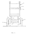
- the wheelchair comprises a frame 1 of generally known kind and having a pair of front caster wheels 2 and a pair of rear driven wheels 3.
- the wheelchair has side frames 4 of which one supports a control means 5 having a joystick 6.
- a bearer member 7 extends across the lower part of the wheelchair providing a mount and carrier for batteries 8 which are connected to each of the electric motors 9 respectively associated with each driven wheel 3.
- the control means is connected to the batteries and motors for controlling the motors and proportional control for driving and steering the wheelchair.
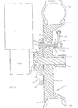
- the motor 9 is connected to a spindle 10 through a reduction worm gearbox 11 to drive the spindle 10 as demanded by the user through the control means.
- a drive plate 12 is fixedly mounted on the inboard portion of the spindle 10 by a cross-key 13.
- the drive plate 12 has an annular flanged portion 14 which is provided with a series of arcuately spaced apart recesses 15.
- the wheel 3 comprises a hub plate 16 having a central boss 17 mounting a bushing 18 through which the outboard end of the spindle 10 extends with there being a circlip retainer 19 mounted on the spindle to hold the wheel on the spindle in known manner.
- a spindle end cap 20 encloses both the spindle end and projecting part of the boss 17.
- the hub plate 16 has an outer rim portion 21 mounting a tyre 22.
- a coupling device 23 is mounted in the hub plate 16 in the web portion intermediate the boss 17 and the rim 21.
- the coupling device 23 comprises a headed coupling pin 24 extending substantially parallel to the spindle 10 received in a counterbore 25 that extends both through the hub plate and a pillar boss 26 projecting outwardly of the hub plate 16.
- the larger end of the counterbore 25 receives a spring 27 arranged to act on the head of the pin 24 to urge same outwardly of the bore 25 towards and into an aligned recess 15 of the drive plate 12.
- the other end of the coupling pin 24 extends through the smaller part of the bore 25 and mounts a lever 28 that is accessible to the user outboard and just above the wheel centre as shown in Figure 1.
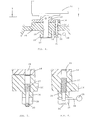
- the pillar boss 26 is formed with a tranverse opening 29 in the form of diametric slot and the rod 30 of the lever 28 extends through a tranverse bore in the free end of the coupling pin 24.
- the rod 30 projects on either side of the end of the pin 24 and, as shown in Figures 3,4 and 6 is received within the transverse opening 29 and confined therein to provide a first located position of the lever 28 in which the headed pin engages with a respective recess 15 in the drive plate 12.
- the spring bias acting on the head of the coupling pin 24 maintains the coupling pin in engagement with the drive plate recess and the lever 28 cannot be inadvertently turned due to the interference of the side walls of the slot in the pillar boss 26.
- the outer end face of the pillar boss 26 is formed with a channel groove 31 for locating the rod 30 in a second position as shown in Figure 5 in which the coupling pin 24 is displaced against the spring bias to disengage the head of the pin from the recess 15 by pulling and turning the lever 28 through 90° until seated in the groove 31.
- the coupling pin is located in the second disengaged position, and due to the spring biass acting on the coupling pin, the lever 28 is biassed and maintained in engagement with the groove 31 against inadvertent displacement.
- the drive plate has a series of twelve recesses 15 uniformly spaced around the flange 14 with each recess having a centre radially equi-spaced from the centre of the spindle 10 so that the coupling pin 24 may engage any one of the recesses 15 by rotating the wheel just a small arcuate distance if, on recoupling, the drive plate is not aligned with a recess 15 in register with the coupling pin head.
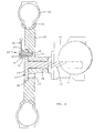
- the hub plate 16, rotatably mounted on the spindle 10 by bushing 18, has an annular recess 40 on the outboard side in which the drive plate 12, fixedly mounted on the outboard end of the spindle 10, is received to hold the wheel 3 on the spindle 10, and the coupling device 23 is mounted in the drive plate 12 in the annular flanged portion 14 for engagement with the hub plate 16.
- the coupling device 23 is of similar construction to that of the first embodiment and comprises the headed coupling pin 24 extending substantially parallel to the spindle 10 in the counterbore formed in the drive plate 12 and the pillar boss 26 which projects outwardly of the drive plate 12.
- the series of arcuately spaced pin receiving recesses 15 are provided in the hub plate 16 and the coupling pin 24 is biassed by the spring 27 located in the counterbore to engage a selected aligned one of the recesses 15 for coupling the drive plate 12 and hub plate 16 together for driven rotation of the wheel 3 by the motor 9.
- the coupling pin 24 is withdrawn from the recess 15 to uncouple the drive plate 12 and hub plate 16 for free rotation of the wheel 3 on the spindle 10 by pulling and turning the lever 28 provided at the outer end of the coupling pin 24 to locate the lever rod 30 in the channel groove (not shown) formed in the outer end face of the pillar boss 26 and is recoupled by the reverse operation as described in the first embodiment.
- the wheelchair user can both couple and uncouple the drive to the wheels of the wheelchair by a simple lever movement not requiring any particular skill nor an attendant.
- the coupling device is very simple, and can be provided for various types of motors as may be used on wheelchairs.
- the coupling device can be applied to wheelchairs having front wheel drive.
- the lever for operating the coupling pin may be arranged in a different manner, for instance the pillar boss could have cam faces in the slot to act in guiding the lever between the two located positions.
- the lever may be pivotally mounted on the end of the coupling pin with the slot being stepped from one side to the other so that the lever is located in one step for the first position and on turning through 180° is located in the other step for the axially displaced second position.
- recesses may be varied, and eight or six recess may be sufficient for some sizes and applications of this invention.
- the recesses in the embodiments as just described are shown as through holes, but the recesses may be formed as blind bores if desired.
- the arrangement and configuration of the wheel may be varied within the scope of this invention, and the pillar boss may not be an integral part of the hub plate ( Figures 3 to 7) or the drive plate ( Figure 8).
- the coupling device could be an assembly to be bolted or otherwise secured to a hub plate or drive plate at the appropriate position.
- the drive plate and the hub plate would engage each other when the coupling pin is engaged in the recess in order to provide thrust faces for drive transmission.
Landscapes
- Engineering & Computer Science (AREA)
- Mechanical Engineering (AREA)
- Animal Behavior & Ethology (AREA)
- General Health & Medical Sciences (AREA)
- Health & Medical Sciences (AREA)
- Veterinary Medicine (AREA)
- Public Health (AREA)
- Life Sciences & Earth Sciences (AREA)
- General Engineering & Computer Science (AREA)
- Chemical & Material Sciences (AREA)
- Combustion & Propulsion (AREA)
- Transportation (AREA)
- Automatic Cycles, And Cycles In General (AREA)
- Brushes (AREA)
- Power Steering Mechanism (AREA)
- Carriages For Children, Sleds, And Other Hand-Operated Vehicles (AREA)
- Gas-Filled Discharge Tubes (AREA)
- Arrangement Or Mounting Of Propulsion Units For Vehicles (AREA)
- Transmission Devices (AREA)
- Handcart (AREA)
Claims (10)
10. Rollstuhl nach Anspruch 8, dadurch gekennzeichnet, daß der pfeilerförmige Anguß (26) Nockenoberflächen in dem Schlitz (29) aufweist, die zur Führung des Bedienungshandgriffes (28) zwischen den beiden Endstellungen dienen.
Priority Applications (1)
| Application Number | Priority Date | Filing Date | Title |
|---|---|---|---|
| AT87108361T ATE64090T1 (de) | 1986-07-05 | 1987-06-10 | Antrieb fuer elektrischen rollstuhl. |
Applications Claiming Priority (2)
| Application Number | Priority Date | Filing Date | Title |
|---|---|---|---|
| GB8616434 | 1986-07-05 | ||
| GB868616434A GB8616434D0 (en) | 1986-07-05 | 1986-07-05 | Drive for electric wheelchairs |
Publications (3)
| Publication Number | Publication Date |
|---|---|
| EP0252322A2 EP0252322A2 (de) | 1988-01-13 |
| EP0252322A3 EP0252322A3 (en) | 1988-06-08 |
| EP0252322B1 true EP0252322B1 (de) | 1991-06-05 |
Family
ID=10600621
Family Applications (1)
| Application Number | Title | Priority Date | Filing Date |
|---|---|---|---|
| EP87108361A Expired - Lifetime EP0252322B1 (de) | 1986-07-05 | 1987-06-10 | Antrieb für elektrischen Rollstuhl |
Country Status (4)
| Country | Link |
|---|---|
| EP (1) | EP0252322B1 (de) |
| AT (1) | ATE64090T1 (de) |
| DE (1) | DE3770531D1 (de) |
| GB (2) | GB8616434D0 (de) |
Cited By (1)
| Publication number | Priority date | Publication date | Assignee | Title |
|---|---|---|---|---|
| WO2009000011A1 (en) * | 2007-06-27 | 2008-12-31 | Clausen Gregory N | Transmission system for a cycle |
Families Citing this family (6)
| Publication number | Priority date | Publication date | Assignee | Title |
|---|---|---|---|---|
| WO1992004200A1 (en) * | 1990-09-04 | 1992-03-19 | Fortress Lite-Style, Inc. | Foldable wheelchair with optional power or manual drive |
| US5197559A (en) * | 1990-09-04 | 1993-03-30 | Fortress Life-Style, Inc. | Foldable wheelchair with optional power or manual drive |
| US5161630A (en) * | 1990-09-04 | 1992-11-10 | Fortress Lite-Style, Inc. | Wheelchair drive assembly |
| DE4127257A1 (de) * | 1991-08-17 | 1993-02-18 | Haas & Alber Haustechnik Und A | Kleinfahrzeug, insbesondere rollstuhl mit faltbarem stuhlgestell |
| US5562174A (en) * | 1993-09-07 | 1996-10-08 | Chen; Sen-Jung | Wheel assembly for a wheelchair |
| FR3150708B1 (fr) * | 2023-07-04 | 2025-08-29 | Mangenot Jean Marie | Axe pour fauteuil roulant permettant le couplage et le découplage d’une roue avec un dispositif de motorisation porté par ledit fauteuil |
Family Cites Families (6)
| Publication number | Priority date | Publication date | Assignee | Title |
|---|---|---|---|---|
| US1189195A (en) * | 1916-05-22 | 1916-06-27 | J And A Carter | Electrically-propelled invalid-chair. |
| AT285810B (de) * | 1968-10-01 | 1970-11-10 | Meyer Fa Wilhelm | Krankenfahrstuhl |
| GB1363649A (en) * | 1971-11-24 | 1974-08-14 | Dudley Controls Ltd | Invalid carrieages |
| GB1463500A (en) * | 1973-06-09 | 1977-02-02 | Cragg H | Wheelchairs |
| GB2102360B (en) * | 1981-06-26 | 1984-11-28 | Barrett Limited W And F | Wheelchair motorised drive unit |
| GB2188839B (en) * | 1985-03-20 | 1989-11-29 | Castro Convertibles Corp | Mattress guard |
-
1986
- 1986-07-05 GB GB868616434A patent/GB8616434D0/en active Pending
-
1987
- 1987-06-10 EP EP87108361A patent/EP0252322B1/de not_active Expired - Lifetime
- 1987-06-10 DE DE8787108361T patent/DE3770531D1/de not_active Expired - Lifetime
- 1987-06-10 AT AT87108361T patent/ATE64090T1/de not_active IP Right Cessation
- 1987-06-30 GB GB8715300A patent/GB2192161B/en not_active Expired
Cited By (1)
| Publication number | Priority date | Publication date | Assignee | Title |
|---|---|---|---|---|
| WO2009000011A1 (en) * | 2007-06-27 | 2008-12-31 | Clausen Gregory N | Transmission system for a cycle |
Also Published As
| Publication number | Publication date |
|---|---|
| EP0252322A2 (de) | 1988-01-13 |
| ATE64090T1 (de) | 1991-06-15 |
| GB8715300D0 (en) | 1987-08-05 |
| DE3770531D1 (de) | 1991-07-11 |
| GB8616434D0 (en) | 1986-08-13 |
| GB2192161B (en) | 1989-05-04 |
| GB2192161A (en) | 1988-01-06 |
| EP0252322A3 (en) | 1988-06-08 |
Similar Documents
| Publication | Publication Date | Title |
|---|---|---|
| KR830002124B1 (ko) | 자동차 차동기어 장치의 액슬축 단절장치 | |
| CA1109295A (en) | Planetary transmission with hydraulic engagement and disengagement | |
| JP3002040B2 (ja) | デファレンシャル装置 | |
| EP4122733B1 (de) | Kupplungsvorrichtung und parkstruktur für doppelstromquellen-antriebsdrehzahlreduzierer | |
| US6827663B2 (en) | Differential gear | |
| EP1543248B1 (de) | Bidirektionale freilaufkupplung für eine primärantriebsachse | |
| US6991571B2 (en) | Variable ratio drive system | |
| US6540640B2 (en) | Power on demand differential | |
| US6837819B2 (en) | Transfer case with two planetary gear sets having a common carrier | |
| US4230211A (en) | Free wheel hub apparatus for vehicles | |
| JPH06280947A (ja) | 駆動車軸の差動装置用調整ロック機構 | |
| JPH10196770A (ja) | 選択的に制動されるトランスファケース等用のプラネタリギヤキャリヤ | |
| US5267915A (en) | Planetary wheel drive assembly | |
| JP2006029586A (ja) | 差動駆動アクチュエータ | |
| EP0252322A2 (de) | Antrieb für elektrischen Rollstuhl | |
| JPH0811490B2 (ja) | 油圧式トランスアクスルアセンブリ | |
| US4498552A (en) | Lawn mower friction drive mechanism | |
| GB2391595A (en) | Transfer case with clutch engaged by a ball screw actuator | |
| US5366040A (en) | Braking device for a working vehicle | |
| US6942082B1 (en) | Drive coupling | |
| US5067934A (en) | Differential gear mechanism | |
| EP0024100A2 (de) | Getriebe | |
| US4244316A (en) | Marine vessel safeguard steering mechanism | |
| US20230256818A1 (en) | Interchangable wheel hub modules | |
| US7070035B2 (en) | Two-way coupling apparatus and method |
Legal Events
| Date | Code | Title | Description |
|---|---|---|---|
| PUAI | Public reference made under article 153(3) epc to a published international application that has entered the european phase |
Free format text: ORIGINAL CODE: 0009012 |
|
| AK | Designated contracting states |
Kind code of ref document: A2 Designated state(s): AT BE CH DE ES FR GR IT LI LU NL SE |
|
| PUAL | Search report despatched |
Free format text: ORIGINAL CODE: 0009013 |
|
| AK | Designated contracting states |
Kind code of ref document: A3 Designated state(s): AT BE CH DE ES FR GR IT LI LU NL SE |
|
| 17P | Request for examination filed |
Effective date: 19881015 |
|
| 17Q | First examination report despatched |
Effective date: 19900711 |
|
| GRAA | (expected) grant |
Free format text: ORIGINAL CODE: 0009210 |
|
| AK | Designated contracting states |
Kind code of ref document: B1 Designated state(s): AT BE CH DE ES FR GR IT LI LU NL SE |
|
| PG25 | Lapsed in a contracting state [announced via postgrant information from national office to epo] |
Ref country code: IT Free format text: LAPSE BECAUSE OF FAILURE TO SUBMIT A TRANSLATION OF THE DESCRIPTION OR TO PAY THE FEE WITHIN THE PRE;WARNING: LAPSES OF ITALIAN PATENTS WITH EFFECTIVE DATE BEFORE 2007 MAY HAVE OCCURRED AT ANY TIME BEFORE 2007. THE CORRECT EFFECTIVE DATE MAY BE DIFFERENT FROM THE ONE RECORDED.SCRIBED TIME-LIMIT Effective date: 19910605 Ref country code: GR Free format text: LAPSE BECAUSE OF FAILURE TO SUBMIT A TRANSLATION OF THE DESCRIPTION OR TO PAY THE FEE WITHIN THE PRESCRIBED TIME-LIMIT Effective date: 19910605 Ref country code: SE Effective date: 19910605 Ref country code: CH Effective date: 19910605 Ref country code: LI Effective date: 19910605 Ref country code: AT Effective date: 19910605 |
|
| REF | Corresponds to: |
Ref document number: 64090 Country of ref document: AT Date of ref document: 19910615 Kind code of ref document: T |
|
| PG25 | Lapsed in a contracting state [announced via postgrant information from national office to epo] |
Ref country code: LU Free format text: LAPSE BECAUSE OF NON-PAYMENT OF DUE FEES Effective date: 19910630 |
|
| REF | Corresponds to: |
Ref document number: 3770531 Country of ref document: DE Date of ref document: 19910711 |
|
| ET | Fr: translation filed | ||
| REG | Reference to a national code |
Ref country code: CH Ref legal event code: PL |
|
| PG25 | Lapsed in a contracting state [announced via postgrant information from national office to epo] |
Ref country code: ES Free format text: LAPSE BECAUSE OF FAILURE TO SUBMIT A TRANSLATION OF THE DESCRIPTION OR TO PAY THE FEE WITHIN THE PRESCRIBED TIME-LIMIT Effective date: 19910916 |
|
| PLBE | No opposition filed within time limit |
Free format text: ORIGINAL CODE: 0009261 |
|
| STAA | Information on the status of an ep patent application or granted ep patent |
Free format text: STATUS: NO OPPOSITION FILED WITHIN TIME LIMIT |
|
| 26N | No opposition filed | ||
| PGFP | Annual fee paid to national office [announced via postgrant information from national office to epo] |
Ref country code: FR Payment date: 19950529 Year of fee payment: 9 |
|
| PGFP | Annual fee paid to national office [announced via postgrant information from national office to epo] |
Ref country code: BE Payment date: 19950607 Year of fee payment: 9 |
|
| PGFP | Annual fee paid to national office [announced via postgrant information from national office to epo] |
Ref country code: NL Payment date: 19950629 Year of fee payment: 9 |
|
| PGFP | Annual fee paid to national office [announced via postgrant information from national office to epo] |
Ref country code: DE Payment date: 19950720 Year of fee payment: 9 |
|
| PG25 | Lapsed in a contracting state [announced via postgrant information from national office to epo] |
Ref country code: BE Effective date: 19960630 |
|
| BERE | Be: lapsed |
Owner name: THE SPASTICS SOCIETY Effective date: 19960630 |
|
| PG25 | Lapsed in a contracting state [announced via postgrant information from national office to epo] |
Ref country code: NL Effective date: 19970101 |
|
| PG25 | Lapsed in a contracting state [announced via postgrant information from national office to epo] |
Ref country code: FR Effective date: 19970228 |
|
| PG25 | Lapsed in a contracting state [announced via postgrant information from national office to epo] |
Ref country code: DE Effective date: 19970301 |
|
| NLV4 | Nl: lapsed or anulled due to non-payment of the annual fee |
Effective date: 19970101 |
|
| REG | Reference to a national code |
Ref country code: FR Ref legal event code: ST |