EP0252416A2 - Isolationsprüfschaltung für gasisolierte Geräte - Google Patents
Isolationsprüfschaltung für gasisolierte Geräte Download PDFInfo
- Publication number
- EP0252416A2 EP0252416A2 EP87109411A EP87109411A EP0252416A2 EP 0252416 A2 EP0252416 A2 EP 0252416A2 EP 87109411 A EP87109411 A EP 87109411A EP 87109411 A EP87109411 A EP 87109411A EP 0252416 A2 EP0252416 A2 EP 0252416A2
- Authority
- EP
- European Patent Office
- Prior art keywords
- voltage
- polarity
- insulation
- test
- impulse
- Prior art date
- Legal status (The legal status is an assumption and is not a legal conclusion. Google has not performed a legal analysis and makes no representation as to the accuracy of the status listed.)
- Granted
Links
- 238000012360 testing method Methods 0.000 title claims abstract description 59
- 238000009413 insulation Methods 0.000 title claims abstract description 46
- 230000010355 oscillation Effects 0.000 claims description 4
- 239000002245 particle Substances 0.000 description 18
- 230000015556 catabolic process Effects 0.000 description 9
- 238000010586 diagram Methods 0.000 description 8
- 239000003990 capacitor Substances 0.000 description 5
- 239000012212 insulator Substances 0.000 description 4
- 238000001514 detection method Methods 0.000 description 3
- 238000000034 method Methods 0.000 description 3
- 230000035945 sensitivity Effects 0.000 description 3
- 239000004020 conductor Substances 0.000 description 2
- 230000005684 electric field Effects 0.000 description 2
- 238000013100 final test Methods 0.000 description 2
- 125000006850 spacer group Chemical group 0.000 description 2
- 238000004804 winding Methods 0.000 description 2
- 238000013016 damping Methods 0.000 description 1
- 230000002950 deficient Effects 0.000 description 1
- 238000002474 experimental method Methods 0.000 description 1
- 238000009434 installation Methods 0.000 description 1
- 238000004519 manufacturing process Methods 0.000 description 1
- 230000001105 regulatory effect Effects 0.000 description 1
- 238000007493 shaping process Methods 0.000 description 1
- 230000035939 shock Effects 0.000 description 1
Images


Classifications
-
- G—PHYSICS
- G01—MEASURING; TESTING
- G01R—MEASURING ELECTRIC VARIABLES; MEASURING MAGNETIC VARIABLES
- G01R31/00—Arrangements for testing electric properties; Arrangements for locating electric faults; Arrangements for electrical testing characterised by what is being tested not provided for elsewhere
- G01R31/12—Testing dielectric strength or breakdown voltage ; Testing or monitoring effectiveness or level of insulation, e.g. of a cable or of an apparatus, for example using partial discharge measurements; Electrostatic testing
-
- G—PHYSICS
- G01—MEASURING; TESTING
- G01R—MEASURING ELECTRIC VARIABLES; MEASURING MAGNETIC VARIABLES
- G01R31/00—Arrangements for testing electric properties; Arrangements for locating electric faults; Arrangements for electrical testing characterised by what is being tested not provided for elsewhere
- G01R31/12—Testing dielectric strength or breakdown voltage ; Testing or monitoring effectiveness or level of insulation, e.g. of a cable or of an apparatus, for example using partial discharge measurements; Electrostatic testing
- G01R31/1227—Testing dielectric strength or breakdown voltage ; Testing or monitoring effectiveness or level of insulation, e.g. of a cable or of an apparatus, for example using partial discharge measurements; Electrostatic testing of components, parts or materials
- G01R31/1254—Testing dielectric strength or breakdown voltage ; Testing or monitoring effectiveness or level of insulation, e.g. of a cable or of an apparatus, for example using partial discharge measurements; Electrostatic testing of components, parts or materials of gas-insulated power appliances or vacuum gaps
Definitions
- the present invention relates to an insulation testing device for a gas insulated apparatus, and particularly relates to an insulation testing device for testing an initial state of defective insulation by effectively detecting electrically-conductive (herein strictlyafter simply referred to as "conductive") foreign particles attached to the surfaces of insulators of a gas insulated apparatus, which become harmful in the operating condition.
- conductive electrically-conductive
- an AC voltage of a commercial frequency has been used as a test voltage when an insulation test of a gas insulated apparatus is carried out at a place where the gas insulated apparatus is installed, as described in "Electrical Cooperative Research", Vol. 39, No. 6, February in l984, page l33, issued by The Society of Electrical Cooperative Research.
- a relatively low voltage equivalent to ll0% of an operating voltage of a gas insulated apparatus has been employed as a test voltage used in the test of the apparatus in the location where the apparatus is installed, because it has been supposed that the final test at factory has been sufficiently carried out for the gas insulated apparatus.
- the insulation property of a gas insulated apparatus is often remarkably lowered unlike that of an conventional air insulated apparatus when contaminated with fine conductive foreign particles.
- conductive foreign particles in an applied electric field are floated by electrostatic force so as to stray within the gas insulated apparatus, because the duration of voltage application is too long.
- the conductive foreign particles which are present in a relatively low intensity electric field in the initial state of an insulation test may be moved and attached to a part of the insulated apparatus so as to be harmful to insulation.
- lowering of insulation little occurs when the conductive foreign particles stray in a gas space, but great lowering of insulation occurs when the foreign particles are attached to the insulator surface.
- the insulation test voltage at the location of installation of the gas insulated apparatus must be made as high as possible.
- an AC voltage of a commercial frequency equivalent to 75 to 80% of an insulation test voltage at factory has been employed as the test voltage as described in the aforementioned paper.
- the voltage shows a value l.7 times to 2 times as much as a normal operating voltage.
- One of the problems relates to the value of the on-site test voltage.
- Application of a voltage higher than an AC voltage of a commercial frequency is most effective in view of reliability, but the maximum value of an AC voltage of a commercial frequency in the operating state is not larger than about l30% of the rated operation voltage of the apparatus.
- Application of a voltage higher than l30% of the rated operation voltage induces a possibility that conductive foreign particles harmless in general may be moved to a part of the insulated apparatus so as to become harmful to insulation.
- the other problem relates to the applied voltage waveform in the actual operating state.
- the excessive voltage over l30% of the rated operation voltage is different in waveform from a commercial frequency voltage but has a waveform of a short-duration switching impulsive voltage. Further, it is necessary to determine the maximum value of the applied voltage taking even a limit voltage of a lightning arrester or the like into consideration.
- the insulation testing device of the invention is arranged so that an insulation test voltage in which a voltage of a positive polarity and a voltage of a negative polarity each having a duration shorter than a half period of a commercial frequency voltage appears alternately, is applied to a high voltage part of a gas insulated apparatus.
- the insulation property widely varies depending on the waveforms of the applied voltage.
- the waveform of a commercial frequency voltage is most severe for the insulation property.
- the insulation characteristics obtained upon application of a switching impulse voltage waveform in which a positive polarity and a negative polarity appear alternately onto a gas insulated apparatus is substantially the same as those obtained upon application of a commercial frequency voltage waveform onto the same apparatus. Therefore, the aforementioned problems are solved by use of a high voltage generator capable of generating such a switching impulse voltage waveform.
- an insulating part of a gas insulated apparatus can be tested under the actual operating conditions. Accordingly, when conductive foreign particles are attached to an insulating part of a gas insulated apparatus, the insulation characteristics at the insulating part can be maintained substantially equally to those in the case of application of a commercial frequency voltage, and it is possible to avoid application of a commercial frequency voltage which is impossible to be generated in an actual case.
- the dielectric strength of an insulated apparatus can be prevented from being designed excessively, resulting in reduction in manufacturing cost of the insulated apparatus.
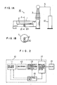
- Fig. lA shows an arrangement of the high voltage part of a gas insulated apparatus to be tested in the present invention
- Fig. lB shows a cross section of the high voltage part.
- a high voltage conductor 2 acting as a bus bar is disposed within a grounded tank l of the gas insulated apparatus and fixedly supported by an insulating spacer 20 so as to be insulated from other parts.
- a bushing 3 is provided at the part where the high voltage conductor 2 acting as a bus bar is led out in the air.
- a high test voltage is applied through the bushing 3 by a test voltage generator l0 at a final test when the assembling of the aforementioned gas insulated apparatus is finished.
- Fig. 2 is a block diagram showing the test voltage generator l0 according to the present invention.
- an AC voltage supplied from an AC voltage source ll is converted into a DC voltage by a rectifier l2.
- the DC voltage is switched over by a polarity changeover switch l3 so as to produce an output in which a positive voltage and a negative voltage appear alternately.
- the output voltage of the polarity changeover switch l3 is applied to an impulse voltage generator l4.
- the impulse voltage generator l4 may be a known one used generally. That is, in the impulse voltage generator l4, electrical charges accumulated in a capacitor is discharged to a suitable wave-shaping circuit through a gap to thereby generate an impulse voltage of a desired waveform. Thus, a test voltage of the necessary waveform (that will be described in detail later) is applied to the gas insulated apparatus to be tested, through a voltage application line 5 from the shock voltage generator l4.
- Fig. 3 is an electric circuit diagram of the test voltage generator l0 of Fig. 2.
- an AC voltage from an AC source ll0 is applied to a voltage regulator ll2 through a switch lll having a pair of contacts for making and breaking the circuit.
- the AC voltage regulated by the voltage regulator ll2 is applied to the primary winding of a main transformer ll3, so that a boosted high voltage is generated from the secondary winding of the main transformer ll3.
- the make-and-break operation of the switch lll and the voltage regulation of the voltage regulator ll2 are controlled by a voltage source control circuit l5l of a control unit l5.
- the rectifier l2 includes a pair of rectifier elements l2l and a pair of resistors l22 to carry out fully-wave rectification of the high voltage supplied from the main transformer ll3.
- the polarity changeover switch l3 includes a pair of contacts l3l to which the rectified voltages of a positive and a negative polarity are respectively applied from the rectifier l2.
- the changeover operation of the contacts l3l is controlled by a polarity switching control circuit l52 of the control unit l5.
- the impulse voltage generator l4 is illustrated as that of the voltage doubler serial charge type.
- Each of the voltages of the positive and negative polarities from the polarity changeover switch l3 charges main capacitors l42 respectively through charging resistors l40 and l4l.
- a starting signal is generated from a generator starting circuit l53 of the control unit l5.
- the starting signal from the starting circuit l53 is applied between starting gap terminals l43 of the impulse voltage generator l4, so that discharge occurs between the starting gap terminals l43.
- electrical charges accumulated in the capacitors l42 are discharged through discharge gap terminals l44 and damping resistors l45.
- the value of the thus generated impulse voltage is determined by the values of resistors l46 and l47 and a capacitor l48.
- the impulse voltage with alternations of a positive polarity (+V1) and a negative polarity (-V2) as shown in Fig. 4 is employed as a test voltage. It is effective that the time distance Td between a positive polarity voltage (+V1) and a negative polarity voltage (-V2) is made to be as short as possible. In practice, however, there is no problem in insulation characteristics when the time distance Td is selected to be of the order of several minutes. In regard to the procedure of impulse voltage application and the number of times of repetitions, it is necessary that an alternation of a positive polarity voltage and a negative polarity voltage is applied at least once. It is preferable that both polarity inversions, from positive to negative and from negative to positive, are carried out. Accordingly, it is desirable that the impulse voltage of the alternation of positive and negative polarities is applied three or more times.
- an insulation test for detecting harmful conductive foreign particles attached to the insulating spacer 20 and other parts can be carried out with substantially the same detection sensitivity as in the case where a commercial frequency voltage is applied as a test voltage.
- Fig. 5 shows relative breakdown voltage values to various test voltages applied to the gas insulated apparatus when conductive foreign particles are attached to an insulator surface of the gas insulated apparatus.
- the case a is obtained under application of a commercial frequency voltage.
- the breakdown voltage Va in this case is the lowest among various cases.
- the cases b to e are obtained under application of various impulse voltages.
- the values of breakdown voltage are shown relative to the value Va.
- a single polarity lightning impulse voltage (having a wave head length of several ⁇ sec and a wave tail time of l0 ⁇ sec) is applied.
- a lightning impulse voltage of a positive polarity and another ligntning impulse voltage of a negative polarity are applied (the negative polarity voltage is applied after application of the positive polarity voltage).
- the breakdown voltages in the cases b and c are l0% to 20% higher than that in the case a . This shows that the cases b and c are inferior in detection sensitivity for conductive foreign particles.
- a single polarity switching impulse voltage (having a wave front time of l0 to several l00 ⁇ sec and a wave tail time of l000 ⁇ sec) is applied.
- a switching impulse voltage of a positive polarity and another switching impulse voltage of a negative polarity are applied.
- the breakdown voltage in the case d is 50% or more higher than that in the case a , but the breakdown voltage in the case e is substantially equal to that in the case a . This phenomenon was confirmed experimentally.
- the foreign particle detection sensitivity is substantially equalized to that in the case where a commercial frequency voltage is used.
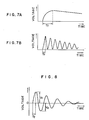
- Fig. 6 shows applied voltage values.
- Symbol a shows the value of a commercial frequency operating voltage Vo.
- the symbol b shows the value of a commercial frequency overvoltage Vac which may occur in operation.
- the symbol c shows the value of a limit voltage Varr due to a lightning arrester or the like provided in the gas insulated apparatus.
- a commercial frequency voltage within the range of from Vo to Vac or an impulsive voltage within the range of from Vac to Varr can be applied to the gas insulated apparatus. Accordingly, any suitable voltage within the range of from Vac to Varr is recommended to be applied in the present invention.
- Figs. 7A and 7B respectively show a simple impulse voltage waveform and a damped oscillation impulse voltage waveform. It is apparent from Fig. 5 that the wave front time Tf of the applied impulse voltage must not be short in order to attain insulation characteristics substantially equal to those in the case where a commercial frequency voltage is applied. According to the results of experiment, it is desirable that the wave front time Tf is several l0 ⁇ sec or more. If only the wave front time is several l0 ⁇ sec or more, the change of the waveform thereafter little affects the insulation characteristics. On the other hand, it is preferable that the wave tail time Tt is short. If the wave tail time is too long (several l000 ⁇ sec or more), the applied voltage affects the movements of conductive foreign particles similarly to the case where a commercial frequency voltage is used.
- Fig. 8 shows another waveform of a test voltage applied to the insulated apparatus.
- the different point from the voltage waveforms of Figs. 7A and 7B is in that the voltage waveform of Fig. 8 oscillates between a positive polarity and a negative polarity.
- the wave front time Tf is several l0 ⁇ sec or more similarly to the case of Fig. 7.
- the first positive polarity shot V1 and second negative polarity shot V2 of the oscillation waveform satisfy the relation: V2/V1 > 0.6, because as shown by the cases d and e in Fig.
- the breakdown voltage upon the application of a single polarity voltage and the breakdown voltage upon the application of a voltage having a polarity which is alternately reversed are lowered at the rate as described above.
Landscapes
- Physics & Mathematics (AREA)
- General Physics & Mathematics (AREA)
- Testing Relating To Insulation (AREA)
Applications Claiming Priority (2)
| Application Number | Priority Date | Filing Date | Title |
|---|---|---|---|
| JP61163272A JPS6319570A (ja) | 1986-07-11 | 1986-07-11 | ガス絶縁機器の試験方法 |
| JP163272/86 | 1986-07-11 |
Publications (3)
| Publication Number | Publication Date |
|---|---|
| EP0252416A2 true EP0252416A2 (de) | 1988-01-13 |
| EP0252416A3 EP0252416A3 (en) | 1989-11-15 |
| EP0252416B1 EP0252416B1 (de) | 1995-08-30 |
Family
ID=15770655
Family Applications (1)
| Application Number | Title | Priority Date | Filing Date |
|---|---|---|---|
| EP87109411A Expired - Lifetime EP0252416B1 (de) | 1986-07-11 | 1987-06-30 | Isolationsprüfschaltung für gasisolierte Geräte |
Country Status (7)
| Country | Link |
|---|---|
| US (1) | US4829256A (de) |
| EP (1) | EP0252416B1 (de) |
| JP (1) | JPS6319570A (de) |
| KR (1) | KR950013413B1 (de) |
| CN (1) | CN1009032B (de) |
| CA (1) | CA1268813A (de) |
| DE (1) | DE3751490T2 (de) |
Cited By (1)
| Publication number | Priority date | Publication date | Assignee | Title |
|---|---|---|---|---|
| AU616250B2 (en) * | 1988-04-18 | 1991-10-24 | Ergon Energy Corporation Limited | Instrument transformer testing apparatus |
Families Citing this family (16)
| Publication number | Priority date | Publication date | Assignee | Title |
|---|---|---|---|---|
| US5214595A (en) * | 1988-05-16 | 1993-05-25 | Hitachi, Ltd. | Abnormality diagnosing system and method for a high voltage power apparatus |
| JPH0738011B2 (ja) * | 1988-05-16 | 1995-04-26 | 株式会社日立製作所 | 高圧電力機器の異常診断システム |
| EP0491554B1 (de) * | 1990-12-17 | 1996-05-22 | Patented Devices (Proprietary) Limited | Überwachung von Teilentladungen |
| DE19639023A1 (de) * | 1996-09-23 | 1998-03-26 | Haefely Trench Ag | Impulsspannungsgeneratorschaltung |
| JP4936846B2 (ja) * | 2006-10-12 | 2012-05-23 | 株式会社東芝 | センサ付きicタグ適用絶縁スペーサ |
| JP5421538B2 (ja) * | 2008-01-10 | 2014-02-19 | 株式会社日本テクナート | 絶縁耐電圧試験方法及び装置 |
| EP2133703B1 (de) * | 2008-06-12 | 2011-10-12 | ABB Technology AG | Prüfanordnung zur Stossspannungsprüfung von elektrischen Hochspannungskomponenten |
| DE102009012114B4 (de) * | 2009-03-06 | 2016-04-21 | Maschinenfabrik Reinhausen Gmbh | Gesteuerte Abschneidefunkenstrecke sowie elektrische Anlage mit einer gesteuerten Abschneidefunkenstrecke |
| EP2485313B1 (de) * | 2009-09-30 | 2021-11-24 | Dai Nippon Printing Co., Ltd. | Vorrichtung zur überprüfung von isolationsausfällen, verfahren zur überprüfung von isolationsausfällen damit sowie verfahren zur herstellung einer elektrochemischen zelle |
| CN102721905A (zh) * | 2012-05-28 | 2012-10-10 | 上海华力微电子有限公司 | 提高绝缘体击穿电压失效分析效率的测试结构及使用方法 |
| CN103823167A (zh) * | 2014-03-14 | 2014-05-28 | 云南电力试验研究院(集团)有限公司电力研究院 | 一种电力用2mv便携式快前沿紧凑型现场冲击试验装置及其控制方法 |
| CN103837805A (zh) * | 2014-03-14 | 2014-06-04 | 云南电力试验研究院(集团)有限公司电力研究院 | 一种现场用gis雷电耐压试验装置 |
| CN107271739A (zh) * | 2017-07-19 | 2017-10-20 | 国网湖南省电力公司 | 一种10kV工频续流试验装置的一次侧保护电路 |
| CN107329059A (zh) * | 2017-07-19 | 2017-11-07 | 西安交通大学 | 一种gis内自由导电微粒的叠加电压检测装置及方法 |
| KR102220751B1 (ko) * | 2018-11-14 | 2021-02-26 | 주식회사 한라 | 수직 배관 설치시 편심보정 커넥터 유니트 |
| CN111678982B (zh) * | 2020-06-24 | 2022-03-29 | 广东电网有限责任公司电力科学研究院 | 一种用于检测替代气体的气固绝缘相容性的实验方法及装置 |
Family Cites Families (7)
| Publication number | Priority date | Publication date | Assignee | Title |
|---|---|---|---|---|
| US2324835A (en) * | 1942-05-16 | 1943-07-20 | Gen Electric | Impulse tester |
| JPS5239308A (en) * | 1975-09-23 | 1977-03-26 | Omron Tateisi Electronics Co | Data transmission system |
| US4140965A (en) * | 1976-02-25 | 1979-02-20 | Optron, Inc. | Isolation voltage test apparatus |
| GB2029587B (en) * | 1978-08-11 | 1982-09-02 | Tokyo Shibaura Electric Co | Methods and apparatus for diagnosing faults in the insulation of electrical insulator |
| CH634416A5 (de) * | 1978-12-08 | 1983-01-31 | Hochspannung Forsch | Hochspannungspruefanlage zur pruefung einer isolation. |
| JPS59630A (ja) * | 1982-06-28 | 1984-01-05 | Tokyo Electric Co Ltd | 電子料金秤 |
| JPS5934170A (ja) * | 1982-08-20 | 1984-02-24 | Hitachi Ltd | 断路器の充電電流しや断時対地絶縁検証試験法 |
-
1986
- 1986-07-11 JP JP61163272A patent/JPS6319570A/ja active Granted
-
1987
- 1987-06-30 DE DE3751490T patent/DE3751490T2/de not_active Expired - Fee Related
- 1987-06-30 EP EP87109411A patent/EP0252416B1/de not_active Expired - Lifetime
- 1987-07-07 CA CA000541467A patent/CA1268813A/en not_active Expired - Lifetime
- 1987-07-09 KR KR1019870007375A patent/KR950013413B1/ko not_active Expired - Fee Related
- 1987-07-09 US US07/071,358 patent/US4829256A/en not_active Expired - Lifetime
- 1987-07-11 CN CN87104748A patent/CN1009032B/zh not_active Expired
Cited By (1)
| Publication number | Priority date | Publication date | Assignee | Title |
|---|---|---|---|---|
| AU616250B2 (en) * | 1988-04-18 | 1991-10-24 | Ergon Energy Corporation Limited | Instrument transformer testing apparatus |
Also Published As
| Publication number | Publication date |
|---|---|
| EP0252416B1 (de) | 1995-08-30 |
| DE3751490D1 (de) | 1995-10-05 |
| EP0252416A3 (en) | 1989-11-15 |
| KR880002020A (ko) | 1988-04-28 |
| CN87104748A (zh) | 1988-02-03 |
| JPS6319570A (ja) | 1988-01-27 |
| KR950013413B1 (ko) | 1995-11-08 |
| JPH0551105B2 (de) | 1993-07-30 |
| DE3751490T2 (de) | 1996-04-18 |
| CN1009032B (zh) | 1990-08-01 |
| CA1268813A (en) | 1990-05-08 |
| US4829256A (en) | 1989-05-09 |
Similar Documents
| Publication | Publication Date | Title |
|---|---|---|
| EP0252416A2 (de) | Isolationsprüfschaltung für gasisolierte Geräte | |
| US6282106B2 (en) | Power supply for an electrostatic precipitator | |
| EP0226302B1 (de) | Verfahren und Vorrichtung zur Überwachung der Funktion einer Funkenzündungseinrichtung in einem Gasturbinenmotor | |
| US6029640A (en) | Method of detecting an ionization current | |
| He et al. | Effect of AC and switching impulse superimposed voltage on PD characteristics in SF 6 gas | |
| EP1279212B1 (de) | Verfahren zum schutz eines gleichstromgenerators vor überspannung | |
| US4147975A (en) | Synthetic test circuit for a metal encapsulated high voltage circuit breaker | |
| Morcos et al. | Metallic particle movement, corona, and breakdown in compressed gas insulated transmission line systems | |
| Kurihara et al. | PD characteristics in an air-filled void at room temperature under superimposed sinusoidal voltages | |
| White | A pulse method for supplying high-voltage power for electrostatic precipitation | |
| RU2046364C1 (ru) | Устройство для контроля сплошности изоляционного покрытия | |
| Haller et al. | High-voltage field testing of GIS from a physical view-point | |
| Kuznetsov et al. | Comparative analysis of acoustic signals and visual images of high-voltage discharge in transformer oil | |
| SU1359760A1 (ru) | Устройство дл испытаний выключателей на отключение емкостного тока | |
| SU1290182A1 (ru) | Устройство дл контрол высокого напр жени на токоведущих элементах трехфазной электроустановки | |
| Masuda et al. | Production of monopolar ions by traveling wave corona discharge | |
| Ni et al. | The effect of wavefront on the breakdown characteristics of transformer oil under positive impulse voltages | |
| RU2035813C1 (ru) | Высоковольтный аппарат с элегазовой изоляцией для электропередач постоянного тока | |
| Musil et al. | Behavior of transformer insulation under short-time overvoltage | |
| Lefèvre et al. | Dielectric test with oscillating discharge of synthetic insulation cables | |
| Fuhr et al. | Spark laws for the electrical breakdown in liquid hydrocarbons | |
| JPH06109800A (ja) | 部分放電監視方法 | |
| SU1368826A1 (ru) | Устройство дл синтетических испытаний высоковольтного оборудовани | |
| RU1772766C (ru) | Устройство дл измерени параметров разр дов в электрических машинах и аппаратах с экранированным токопроводом | |
| JPS60180442A (ja) | 電源装置 |
Legal Events
| Date | Code | Title | Description |
|---|---|---|---|
| PUAI | Public reference made under article 153(3) epc to a published international application that has entered the european phase |
Free format text: ORIGINAL CODE: 0009012 |
|
| 17P | Request for examination filed |
Effective date: 19870729 |
|
| AK | Designated contracting states |
Kind code of ref document: A2 Designated state(s): CH DE LI |
|
| PUAL | Search report despatched |
Free format text: ORIGINAL CODE: 0009013 |
|
| AK | Designated contracting states |
Kind code of ref document: A3 Designated state(s): CH DE LI |
|
| 17Q | First examination report despatched |
Effective date: 19920324 |
|
| GRAA | (expected) grant |
Free format text: ORIGINAL CODE: 0009210 |
|
| AK | Designated contracting states |
Kind code of ref document: B1 Designated state(s): CH DE LI |
|
| REF | Corresponds to: |
Ref document number: 3751490 Country of ref document: DE Date of ref document: 19951005 |
|
| PLBE | No opposition filed within time limit |
Free format text: ORIGINAL CODE: 0009261 |
|
| STAA | Information on the status of an ep patent application or granted ep patent |
Free format text: STATUS: NO OPPOSITION FILED WITHIN TIME LIMIT |
|
| 26N | No opposition filed | ||
| PGFP | Annual fee paid to national office [announced via postgrant information from national office to epo] |
Ref country code: CH Payment date: 20020409 Year of fee payment: 16 |
|
| PGFP | Annual fee paid to national office [announced via postgrant information from national office to epo] |
Ref country code: DE Payment date: 20020628 Year of fee payment: 16 |
|
| PG25 | Lapsed in a contracting state [announced via postgrant information from national office to epo] |
Ref country code: LI Free format text: LAPSE BECAUSE OF NON-PAYMENT OF DUE FEES Effective date: 20030630 Ref country code: CH Free format text: LAPSE BECAUSE OF NON-PAYMENT OF DUE FEES Effective date: 20030630 |
|
| PG25 | Lapsed in a contracting state [announced via postgrant information from national office to epo] |
Ref country code: DE Free format text: LAPSE BECAUSE OF NON-PAYMENT OF DUE FEES Effective date: 20040101 |
|
| REG | Reference to a national code |
Ref country code: CH Ref legal event code: PL |