EP0252448A2 - Source de lumière du type capsule pour lampe électrique - Google Patents
Source de lumière du type capsule pour lampe électrique Download PDFInfo
- Publication number
- EP0252448A2 EP0252448A2 EP87109581A EP87109581A EP0252448A2 EP 0252448 A2 EP0252448 A2 EP 0252448A2 EP 87109581 A EP87109581 A EP 87109581A EP 87109581 A EP87109581 A EP 87109581A EP 0252448 A2 EP0252448 A2 EP 0252448A2
- Authority
- EP
- European Patent Office
- Prior art keywords
- capsule
- reflector
- light
- hollow bulb
- emitting
- Prior art date
- Legal status (The legal status is an assumption and is not a legal conclusion. Google has not performed a legal analysis and makes no representation as to the accuracy of the status listed.)
- Granted
Links
Images
Classifications
-
- H—ELECTRICITY
- H01—ELECTRIC ELEMENTS
- H01K—ELECTRIC INCANDESCENT LAMPS
- H01K1/00—Details
- H01K1/38—Seals for leading-in conductors
Definitions
- the invention relates to electric lamps and particularly to capsule light sources for electric lamps for use in such applications as down lighting, display lighting, flood lighting and track lighting.
- Electric lamps including those wherein a light-emitting capsule serves as the light source therefor, have been available for years. With particular regard to those lamps used in the aforementioned environments, typically two types have evolved.
- One such lamp referred to in the art as a PAR (parabolic aluminized reflector) type lamp. typically utilizes a glass reflector and separate glass cover in which is positioned a coiled tungsten filament.
- a base member secured 1: 0 the reflector is designed for being positioned within the required socket to provide the necessary connection to a power source (e.g.. 120 VAC) for lamp operation. Examples of such lamps are illustrated in U.S. Patents 4.506.316 (Thiry et al). 4 .
- a second type of lamp of this variety includes a quartz or high silica glass envelope having therein a coiled tungsten filament and also including a base member located on the envelope. the base designed for being positioned within a socket as mentioned above.
- Lamps of this type are referred to in the lighting field with such product designations as R20 (the R standing for reflector).
- R30, R40, ER30 the ER standing for ellipsoidal reflector
- ER40 the ER standing for ellipsoidal reflector
- Examples of such lamps are illustrated in U.S. Patents 4.041.344 (LaGiusa). Re. 30 .832 (LaGiusa) and 4.331.901 (Vrijer et al).
- such lamps utilize only a coiled filament as the source.
- a light-emitting capsule for being oriented within the lamp's reflector in a stable manner. thereby assuring accurate orientation of the capsule's light source relative to the reflector's internal reflecting surfaces. This positioning is attainable in an expeditious fashion while still assuring such accuracy of position. Additionally, the unique design of the capsule affords enhanced heat sinking to thus assure prolonged lamp life.
- a primary object of this invention to enhance the electric lamp field by providing a light-emitting capsule for use in an electric lamp. which capsule can be facilely oriented within the lamp ' s reflector to assure a stable component therein.
- a light-emitting capsule for use in an electric lamp including a reflector having a forward concave reflecting portion, a rear. protruding neck portion and an opening extending through the rear neck portion.
- the capsule includes a hollow bulb portion adapted for being positioned within the concave reflecting portion of the reflector and having a light source disposed therein, and a sealed end portion adjacent the hollow bulb portion and adapted for being positioned within the opening within the rear neck portion of the reflector.
- the sealed end portion is of elongated configuration and includes a protruding end segment thereon, the protruding end segment adapted for engaging the internal surfaces of the opening within the rear neck portion of the reflector to stabilize the capsule within the reflector.
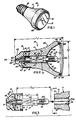
- FIG. 1 there is shown an electric lamp 10 capable of having the light-emitting capsule 13 of the instant invention located therein.
- the invention is not limited to the specific lamp embodiment defined herein, however. in that it is clearly understood that the teachings provided herein are also applicable to other electric lamps wherein a reflector possessing similar characteristics (e.g.. concave reflecting portion and extending rear neck portion) is utilized.
- lamp 10 is highly efficient and of compact. rugged design. That is, lamp 10 is specifically designed for being of relatively small construction while capable of providing light output at levels comparative to the aforementioned, two types of known lamps.
- lamp 10 includes a reflector 11. a light-emitting capsule 13 in accordance with a preferred embodiment of the invention located within the reflector, and a base member 15 which is secured to the reflector and adapted for being positioned within an appropriate socket (not shown) which in turn is electrically coupled to the power source (e.g.. 120 VAC) for providing electrical energy to the lamp (and thus capsule 13).
- Base member 15. as described herein, is of substantially similar external configuration to known bases utilized in lamps of the type described herein such that lamp 10 is readily adaptable for use within existing socket constructions.
- base member 15 possesses an external configuration similar to existing screw bases like those employed in the aforementioned PAR. R. and ER lamps. It is understood. however.
- the capsule of the invention being capable of use in other types of electric lamps, may be used in such lamps which do not include a base member as described herein.
- Examples of such lamps include well known projection lamps commonly referred to in the art as "rim mount" projection lamps wherein a reflector (e.g.. of borosilicate glass) excluding such a base is designed to accommodate a capsule therein.
- rim mount projection lamps wherein a reflector (e.g. of borosilicate glass) excluding such a base is designed to accommodate a capsule therein.
- a reflector e.g.. of borosilicate glass
- Externally projecting conductors of the capsule from the reflector's rear or apex region
- the capsule of the present invention is adaptable for use within such projection and similar type lamps, with relatively minor modification thereto being required.
- base member 15 is positioned on an external surface of the rear. protruding neck portion 17 of reflector 11. Assembly (to be further described with the description of FIG. 3 below) is accomplished by sliding the substantially cylindrically shaped base member onto the similarly configured neck portion. Fixed securement is accomplished using a quantity of ceramic adhesive 19 or the like material, or, alternatively. may be provided by other means.
- One such alternative means is a procedure known as magnetic metalforming wherein an electrical coil is located relative to (about) the base member while the base member is positioned on the reflector's neck portion. A pulsed magnetic field is generated from electric current passing through the coil to exert a controllable pressure on the metal base member. High voltage capacitors are discharged through the coil. making this created field extremely intense. The field in turn induces current in the base member, setting up an opposing magnetic field. As a result, high pressures are generated. causing the metallic base to compress and form a tight fit on the reflector's neck.
- elongated slots 21 are preferably provided within the reflector's neck portion to accommodate additional quantities of ceramic adhesive and thus provide added securement of base member 15 .
- the neck portion's external surface may be substantially smooth and thus devoid of slots such as depicted in the drawings.
- Reflector 11 is preferably of ceramic construction and thus capable of withstanding relatively high temperatures at which lamp 10 is specifically designed to operate.
- reflector temperature for electric lamp 10 during operation thereof exceeded 25 0 degrees Celsius and in one instance (wherein the capsule 13 operated at 100 watts), the corresponding reflector temperature approached 350 degrees Celsius.
- the ability to operate at such relatively high temperatures in a safe and facile manner to provide light output at levels similar to those of the aforementioned type lamps constitutes a significant feature of lamp 10 and is due in part at least to the unique design of the instant invention.
- lamp 10. in one embodiment. possessed an overall length of only about 2.1 4 inches (dimension "L" in FIG. 2) and an overall outer diameter of only about 2.00 inches (dimension "D" in FIG. 2).
- reflector 11 further includes a forward, concave reflecting portion 23 which includes therein the concave reflecting surface 25 designed for reflecting light from capsule 1 3 during lamp operation.
- surface 25 was of substantially parabolic configuration and was glazed during formation of the green ceramic reflector.
- Surface 25 may also be faceted, fluted. peened or otherwise altered to affect light output.
- Steatite ceramic powder or other types of ceramic known in the industry, with controlled particle size. is pressed into the desired shape at high pressure (as is known in the ceramic industry) to obtain a high density "green" part.
- Other known methods such as alipcasting or molding a wet slurry may also be used.
- Liquid glaze is applied, preferably by spraying, onto the area containing the desired contour for the reflective surface while the ceramic is spinning in order to achieve a very precise thin coating.
- the glaze has been formulated such that it may be sintered to obtain a hard smooth surface at the same time and temperature as required for the ceramic to be sintered and fully cured.
- the outside of the ceramic may be glazed with a clear glaze or with colors, surface finishes and patterns as desired for cosmetic purposes. Colorant may also be added to the ceramic bulk material to produce a final product having such a color.
- a metallic reflective coating 27 e.g.. vapor deposited high purity aluminum may be added over the glazed surface after sintering for the purpose of enhancing reflectivity.
- Reflector 11. as shown, includes a central opening 31 therein which, as illustrated, passes from the concave reflecting portion 23 to the outer extremity of rear. neck portion 17.
- opening 31 is preferably of substantially cylindrical configuration and lies coaxial with the optical axis (OA-OA) of the reflector. Accordingly, light-emitting capsule 13 is located substantially within opening 31 such that the hollow bulb portion 33 thereof projects within and is substantially surrounded by the concave reflecting surfaces 25 of the reflector.
- Capsule 13 is preferably a tungsten halogen capsule.
- tungsten halogen capsule By a tungsten halogen capsule is meant a capsule wherein the hollow bulb portion thereof includes a coiled (or coiled coil) tungsten filament (35) as the light source and an internal atmosphere containing a halogen, such as bromine.
- Tungsten halogen technology is known in the art and defines a procedure wherein a regenerative cycle is initiated when a tungsten halide is produced and chemically combines with particles evaporated from the energized filament to thus prevent evaporated tungsten particles from depositing on other filaments (if utilized) or on the envelope wall.
- capsules heretofore used in such technology have been constructed of quartz, high silica glass, or aluninosilicate glass. as is capsule 13.
- capsule 13 may comprise an arc discharge capsule (FIG. 6) of the general variety shown and described in U.S. Patents 4.302.699 (Keeffe et al). 4,321.504 (Keeffe et al) and 4 .454.450 (English et al). all of which are assigned to the assignee of this invention.
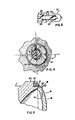
- Lamps having such capsules are also referred to as low wattage metal halide arc lamps and include a pair of spaced-apart electrodes 26 (FIG. 6) which extend within the tube (bulb). An arc is created between the electrodes during lamp operation, this arc serving as the light source.
- Capsules of the arc discharge and tungsten halogen variety typically include a press sealed end portion through which pass at least two electrical conductors which in turn project from the end thereof.
- the capsule of the instant invention includes a new and unique press sealed end portion 37 of substantially elongated configuration in comparison to the capsule's bulb portion.
- the capsule envelope in one embodiment of the invention possessed an overall length (dimension "CL" in FIG . 3) of about 1.70 inch and a corresponding seal length (dimension "SL" in FIG. 3) of about 1.05 inch.
- elongated is thus meant a capsule having a sealed end length within the range of from about thirty percent to about eighty percent of the overall capsule length. In the above example, the sealed length represented about sixty percent of the overall length.
- the sealed portion is longer than the hollow bulb portion of capsule 13.
- elongated conductive foils 39 e.g.. molybdenum
- foils 39 serve to connect the electrodes 26 to respective conductors 41 similar to those shown in FIGS. 2 and 3. It is also understood that those parts of capsule 13 not shown in FIG. 6 are similar to those in FIGS. 2. 3 and 4.
- the outer portions of each of the conductors 41 was comprised of molybdenum material while the corresponding inner portion (that coupled to coiled filament 35. if used) were each of tungsten material. In the arc discharge embodiment in FIG .
- each conductor 41 is in turn electrically coupled to a respective one of the two electrical contact portions of base member 15. As shown in FIG. 2. one conductor 41 is connected to a diode 51 through a conducting wire 53. which diode is in turn electrically connected to the conductive tip contact portion 55 of base member 15. The remaining conductor 41 is connected to the metallic shell contact portion 57 of the base member, preferably by a wire conductor 59.
- the first conductor 53 is preferably of copper material and possesses an outer diameter of about 0.030 inch.
- the second wire conductor 59 was preferably of three parts (only one shown in the drawings for illustration purposes), each of nickel material and butt-welded to form a singular element. The three parts possessed outer diameters of 0.0 20 inch. 0 . 00 6 inch and 0.020 inch. respectively. Wire 59. having this small diameter middle part. thus serves as a fusible element.
- the outer shell contact portion 57 of base member 15 in one example was of nickel-plated brass, as was the tip contact portion 55. Understandably, solder (not shown) may be utilized in base configurations of this type to provide connections between such elements as disclosed herein.
- diode 51 is sealed within a quantity of ceramic adhesive 61 or the like which in turn is located within a reservoir portion of electrically insulative material 63 (e.g., glass) which also forms part of base member 15.
- This ceramic adhesive which covers the diode, thus serves to insulate this component from heat generated by capsule 13 during lamp operation.
- the ceramic adhesive utilized for material 61 was also white in color to thus reflect heat away from the diode.
- Dylon 07 adhesive sold by Dylon Industries. Inc.. Berea. Ohio 44017.
- the purpose of utilizing diode 51 is to reduce the line voltage for lamp 10.
- the aforementioned 120 VAC was reduced to 84 VAC to thus allow a more rugged and efficient tungsten coil. Accordingly, a coil less prone to sag or damage (e.g.. during handling) is possible.
- the elongated sealed end portion 37 of capsule 13 is shown to include a protruding end segment 71 which is designed for engaging an internal surface of opening 31 within the reflector's neck portion. Such engagement enables the capsule to be oriented in a stable manner within a reflector such as reflector 11 (e.g.. during jarring as may occur during handling).
- the hollow, cylindrical bulb portion of capsule 1 3 also engage the reflector opening's internal surface, thus providing a dual contact at spaced-apart locations between capsule and reflector.
- protruding end segment 71 and bulb portion 33 are both of similar (cylindrical) configuration, with each preferably possessing similar outer diameters.
- segment 71 and bulb 33 each possessed an external (outer) diameter of about 0.395 inch.
- the aforementioned sealed portion 37. as shown, also includes a segment 72 of flattened configuration and of a width slightly greater than the corresponding outer diameter for the two capsule parts it joins (segment 71 and bulb portion 33).
- flattened segment 72 had an overall width of about 0. 450 inch and a thickness of only about 0.138 inch.
- capsule 1 3 is secured within the base member 15 to form the assembly depicted in FIG. 3. That is, the projecting conductors 4 1 are secured within the heat insulating ceramic adhesive 61 to provide a rigid capsule and base assembly. This entire assembly is then slidably positioned within the protruding neck portion 17 of reflector 11. as indicated in FIG. 3.
- the protruding end segment 71 and/or cylindrical bulb portion 33 slidably engage the reflector's internal surfaces while the metallic contact portion 57 of the base slidably engages the exterior surface of neck portion 17.
- the aforementioned adhesive 19. if utilized is applied (e.g.. located within the respective slots 21. if utilized).
- the final result of this assembly is a capsule (and internal coil or, alternatively, an arc gap) in fixed. optical alignment within the lamp's reflector.
- the aforementioned assembly technique enables the light center length (the distance from the coiled filament, or. alternatively, the arc location, to the respective reflective surfaces) to be precisely established when the capsule is connected to a base or similar component, such as base member 15.
- the aforementioned optical alignment is thus possible without further manipulation of the capsule after positioning within a lamp reflector such as defined herein.
- Extending the length of the press sealed end portion 37 of the capsule to the extent defined herein has also proven to reduce the seal temperature during lamp operation, thereby extending overall lamp life. That is, major portions of the sealed end are spaced at a substantial distance from the hot bulb portion of the capsule. In one example, a reduced seal temperature of about 100 degrees celsius was observed. It is estimated that such a substantial reduction in temperature will improve lamp life by a factor of five when the lamp is operated in the temperature ranges (e.g.. at 350 degrees celsius) mentioned above.
- a protruding end section 71 (and bulb portion, if desired) of different configuration than the one depicted in the drawings.
- an oblong configuration can be utilized. such that the exterior surfaces thereof engage fewer (e.g.. two) than the total number of projections.
- Such engagement is also possible with an end section and/or bulb portion of cylindrical external configuration.
- only one of the two spaced contacting segments (end segment 71 or bulb portion 33) of capsule 13 contacted only two projections.
- both end segment 71 and the bulb engage all (six) of the opening's projections 75 (i.e., as depicted in FIG. 4).
- the aforementionea point contact relationships between capsule and reflector has also proven advantageous with regard to the reflective coating 27. it utilized in a reflector-type lamp as lamp 10. That is, the defined positioning relationship also serves to adequately space the capsule from such a coating. It has been determined that direct contact between the capsule and such a coating may result in sublimation of the coating, the result of which may be to adversely affect the reflector's reflecting capability. This is overcome by the capsule-reflector positioning relationship described herein.
- electric lamp 10 further includes a light-transmitting cover means 81 which serves to cover the forward opening of the reflector's concave reflecting portion 23 and thus seal capsule 13 therein.
- Cover means 81 preferably of transparent glass material (e.g.. borosilicate). is secured against the forwardmost surfaces of the annular rim portion 83 of reflector 11.
- cover means 81 constituted a lens which served to direct the light output in a predetermined manner to provide the ultimate pattern desired on the subject area being so illuminated. If so used. this lens would preferably include a stippled internal surface (not shown) for diffusing light passing therethrough. particularly when the reflector's internal reflecting surface is faceted, peened. or similarly altered as mentioned above.
- the annular cover means abuts against the aforementioned forwardmost surfaces (85). As also shown, this forwardmost portion of the reflector includes an annular groove or slot 87 therein. Retention of cover means 81 is accomplished by the provision of a holder member 8 9 which, also being of annular configuration, engages the outer surface of the cover means about the periphery thereof. As shown in FIG. 5, holder member 89 is secured within the reflector's groove 81 by a quantity of adhesive 91 (e.g.. ceramic adhesive). Holder member 89 is of thin metallic material (e.g.. aluminum) and.
- adhesive 91 e.g. ceramic adhesive
- the ceramic possessed a coefficient of thermal expansion of about 8.00 x 10 6 cm./co./aegree Celsius while the borosilicate cover means possessed a coefficient of thermal expansion of about 4.00 x 10 -6 cm./ca./degree Celsius.
- the coefficient of thermal expansion for the ceramic adhesive 91 was about 7.50 x 10 -6 cm./cm./degree Celsius. It is thus understood that the cover means is not cemented to the reflector but instead is secured against the reflector in the abutting manner defined. This unique ability of the holder to flex during expansion and contraction of the retained cover prevents damage thereto.
- a light-emitting capsule capable of use within a reflector-type electric lamp of the variety described herein.
- This capsule being of a unique design wherein a long. narrow width sealed end is employed in combination with an adjacent hollow bulb (preferably of shorter length than the sealed end) can be readily positioned within the lamp's reflector in not only stable fashion but also one wherein precise alignment between the capsule's light source (filament or arc) and reflector's reflecting surfaces is assured.
- the capsule's design also promotes heat transference in the neck region of such a reflector and enables a product which can be cost effectively produced on a mass production basis.
Landscapes
- Fastening Of Light Sources Or Lamp Holders (AREA)
- Vessels And Coating Films For Discharge Lamps (AREA)
- Non-Portable Lighting Devices Or Systems Thereof (AREA)
Applications Claiming Priority (2)
| Application Number | Priority Date | Filing Date | Title |
|---|---|---|---|
| US06/882,553 US4728849A (en) | 1986-07-07 | 1986-07-07 | Capsule light source for electric lamp |
| US882553 | 1986-07-07 |
Publications (3)
| Publication Number | Publication Date |
|---|---|
| EP0252448A2 true EP0252448A2 (fr) | 1988-01-13 |
| EP0252448A3 EP0252448A3 (en) | 1989-11-15 |
| EP0252448B1 EP0252448B1 (fr) | 1993-06-09 |
Family
ID=25380832
Family Applications (1)
| Application Number | Title | Priority Date | Filing Date |
|---|---|---|---|
| EP87109581A Expired - Lifetime EP0252448B1 (fr) | 1986-07-07 | 1987-07-03 | Source de lumière du type capsule pour lampe électrique |
Country Status (5)
| Country | Link |
|---|---|
| US (1) | US4728849A (fr) |
| EP (1) | EP0252448B1 (fr) |
| JP (1) | JPS6326944A (fr) |
| CA (1) | CA1287093C (fr) |
| DE (1) | DE3786116D1 (fr) |
Cited By (1)
| Publication number | Priority date | Publication date | Assignee | Title |
|---|---|---|---|---|
| WO2000075957A1 (fr) * | 1999-06-03 | 2000-12-14 | Koninklijke Philips Electronics N.V. | Ensemble lampe/reflecteur electrique |
Families Citing this family (15)
| Publication number | Priority date | Publication date | Assignee | Title |
|---|---|---|---|---|
| US4918353A (en) * | 1987-09-29 | 1990-04-17 | General Electric Company | Reflector and lamp combination |
| US5057735A (en) * | 1989-10-13 | 1991-10-15 | General Electric Company | Reflector lamp unit with independently adjustable lamp mount |
| USD325096S (en) | 1990-09-05 | 1992-03-31 | Applied Lumens, Ltd. | Fluorescent lamp |
| US5506763A (en) * | 1991-09-24 | 1996-04-09 | Carley; Curtis J. | Incandescent bulb and reflector and method for making |
| US6483232B1 (en) * | 2000-07-14 | 2002-11-19 | Amglo Kemlite Laboratories, Inc. | Aviation landing lamp |
| US6641422B2 (en) | 2000-12-06 | 2003-11-04 | Honeywell International Inc. | High intensity discharge lamp and a method of interconnecting a high intensity discharge lamp |
| EP1573244A2 (fr) * | 2002-11-11 | 2005-09-14 | Koninklijke Philips Electronics N.V. | Lampe a reflecteur electrique et procede d'assemblage |
| US8016440B2 (en) | 2005-02-14 | 2011-09-13 | 1 Energy Solutions, Inc. | Interchangeable LED bulbs |
| US7758223B2 (en) * | 2005-04-08 | 2010-07-20 | Toshiba Lighting & Technology Corporation | Lamp having outer shell to radiate heat of light source |
| US20050212396A1 (en) * | 2005-06-21 | 2005-09-29 | Osram Sylvania Inc. | Par lamp with negative draft neck and method of assembling the lamp |
| US8083393B2 (en) * | 2006-02-09 | 2011-12-27 | 1 Energy Solutions, Inc. | Substantially inseparable LED lamp assembly |
| HU0700336D0 (en) * | 2007-05-11 | 2007-07-30 | Ge Hungary Zrt | Bulb-shaped outer envelope for lamps, method for manufacturine thereof and compact fluorescent lamp therewith |
| US8376606B2 (en) * | 2008-04-08 | 2013-02-19 | 1 Energy Solutions, Inc. | Water resistant and replaceable LED lamps for light strings |
| US8314564B2 (en) | 2008-11-04 | 2012-11-20 | 1 Energy Solutions, Inc. | Capacitive full-wave circuit for LED light strings |
| US8836224B2 (en) * | 2009-08-26 | 2014-09-16 | 1 Energy Solutions, Inc. | Compact converter plug for LED light strings |
Family Cites Families (9)
| Publication number | Priority date | Publication date | Assignee | Title |
|---|---|---|---|---|
| US4156271A (en) * | 1976-05-05 | 1979-05-22 | General Electric Company | Reflector lamp |
| NL179433C (nl) * | 1976-06-21 | 1986-09-01 | Philips Nv | Elektrische lamp. |
| US4169237A (en) * | 1978-09-06 | 1979-09-25 | Gte Sylvania Incorporated | High voltage movie light and incandescent lamp unit for use therewith |
| US4243907A (en) * | 1979-07-05 | 1981-01-06 | Gte Products Corporation | Lamp having reduced width press-seal |
| DE2938189C2 (de) * | 1979-09-21 | 1984-07-26 | Patent-Treuhand-Gesellschaft für elektrische Glühlampen mbH, 8000 München | Glühlampe mit am Quetschfuß kittlos befestigten Lampensockel |
| US4321504A (en) * | 1980-03-24 | 1982-03-23 | Gte Products Corporation | Low wattage metal halide arc discharge lamp |
| US4386292A (en) * | 1980-07-02 | 1983-05-31 | Gte Products Corporation | Projection lamp comprising single ended arc discharge lamp and an interference filter |
| DE3221290A1 (de) * | 1982-06-05 | 1983-12-08 | Philips Patentverwaltung Gmbh, 2000 Hamburg | Elektrische lampe mit einem huelsenfoermigen sockel |
| US4608624A (en) * | 1985-01-22 | 1986-08-26 | Gte Products Corporation | Projection lamp unit with separable lamp capsule |
-
1986
- 1986-07-07 US US06/882,553 patent/US4728849A/en not_active Expired - Fee Related
-
1987
- 1987-07-02 CA CA000541035A patent/CA1287093C/fr not_active Expired - Lifetime
- 1987-07-03 DE DE8787109581T patent/DE3786116D1/de not_active Expired - Lifetime
- 1987-07-03 EP EP87109581A patent/EP0252448B1/fr not_active Expired - Lifetime
- 1987-07-07 JP JP62167973A patent/JPS6326944A/ja active Pending
Cited By (1)
| Publication number | Priority date | Publication date | Assignee | Title |
|---|---|---|---|---|
| WO2000075957A1 (fr) * | 1999-06-03 | 2000-12-14 | Koninklijke Philips Electronics N.V. | Ensemble lampe/reflecteur electrique |
Also Published As
| Publication number | Publication date |
|---|---|
| EP0252448A3 (en) | 1989-11-15 |
| DE3786116D1 (de) | 1993-07-15 |
| CA1287093C (fr) | 1991-07-30 |
| US4728849A (en) | 1988-03-01 |
| EP0252448B1 (fr) | 1993-06-09 |
| JPS6326944A (ja) | 1988-02-04 |
Similar Documents
| Publication | Publication Date | Title |
|---|---|---|
| EP0252448B1 (fr) | Source de lumière du type capsule pour lampe électrique | |
| US4755711A (en) | Electric lamp with ceramic reflector | |
| US4298822A (en) | Folded fluorescent lamp and socket | |
| EP2156463B1 (fr) | Lampe fluorescente compacte à enveloppe extérieure et procédé de sa fabrication | |
| EP0443964B1 (fr) | Lampe aux halogénures métalliques à wattage bas | |
| CA1111483A (fr) | Lampe a decharge haute pression de rendement accru | |
| US4290097A (en) | High-pressure discharge lamp and reflector combination | |
| GB2145278A (en) | Incandescent lighting units | |
| US4912364A (en) | Three-phase high-pressure gas discharge lamp filled with a gas containing sodium or a metal-halide | |
| CN100538996C (zh) | 电灯/反射器装置 | |
| US4833574A (en) | Annular fluorescent lamp | |
| US4724353A (en) | Electric lamp with insulating base | |
| US4774432A (en) | Electric lamp with flexible cover holder | |
| EP0156384B1 (fr) | Positionnement d'électrodes et projet de capsule pour lampes à puissance basse à halogène métallique à bout unique | |
| US4918355A (en) | Electric lamp with protective base | |
| EP0252447B1 (fr) | Lampe électrique à porte-couverture flexible | |
| US3622947A (en) | Lamp base extension | |
| US2901648A (en) | Reflector mercury lamp | |
| US2980818A (en) | Projection lamp | |
| US5539271A (en) | Horizontal burning metal halide lamp | |
| US4837479A (en) | Electric lamp with insulating base | |
| JP2003528433A (ja) | ランプ | |
| US4804878A (en) | Electric lamp, base for use therewith and method of assembling same | |
| JPS62168336A (ja) | 街灯及び産業用照明器具 | |
| US6667573B2 (en) | Halogen incandescent lamp |
Legal Events
| Date | Code | Title | Description |
|---|---|---|---|
| PUAI | Public reference made under article 153(3) epc to a published international application that has entered the european phase |
Free format text: ORIGINAL CODE: 0009012 |
|
| 17P | Request for examination filed |
Effective date: 19870728 |
|
| AK | Designated contracting states |
Kind code of ref document: A2 Designated state(s): BE DE FR GB NL |
|
| PUAL | Search report despatched |
Free format text: ORIGINAL CODE: 0009013 |
|
| AK | Designated contracting states |
Kind code of ref document: A3 Designated state(s): BE DE FR GB NL |
|
| 17Q | First examination report despatched |
Effective date: 19910802 |
|
| GRAA | (expected) grant |
Free format text: ORIGINAL CODE: 0009210 |
|
| AK | Designated contracting states |
Kind code of ref document: B1 Designated state(s): BE DE FR GB NL |
|
| PG25 | Lapsed in a contracting state [announced via postgrant information from national office to epo] |
Ref country code: NL Effective date: 19930609 Ref country code: FR Effective date: 19930609 Ref country code: DE Effective date: 19930609 Ref country code: BE Effective date: 19930609 |
|
| REF | Corresponds to: |
Ref document number: 3786116 Country of ref document: DE Date of ref document: 19930715 |
|
| PG25 | Lapsed in a contracting state [announced via postgrant information from national office to epo] |
Ref country code: GB Effective date: 19930909 |
|
| EN | Fr: translation not filed | ||
| NLV1 | Nl: lapsed or annulled due to failure to fulfill the requirements of art. 29p and 29m of the patents act | ||
| PLBE | No opposition filed within time limit |
Free format text: ORIGINAL CODE: 0009261 |
|
| STAA | Information on the status of an ep patent application or granted ep patent |
Free format text: STATUS: NO OPPOSITION FILED WITHIN TIME LIMIT |
|
| GBPC | Gb: european patent ceased through non-payment of renewal fee |
Effective date: 19930909 |
|
| 26N | No opposition filed |