EP0252523A2 - Temperaturfühler - Google Patents
Temperaturfühler Download PDFInfo
- Publication number
- EP0252523A2 EP0252523A2 EP87110021A EP87110021A EP0252523A2 EP 0252523 A2 EP0252523 A2 EP 0252523A2 EP 87110021 A EP87110021 A EP 87110021A EP 87110021 A EP87110021 A EP 87110021A EP 0252523 A2 EP0252523 A2 EP 0252523A2
- Authority
- EP
- European Patent Office
- Prior art keywords
- silicone rubber
- temperature
- temperature sensor
- microswitch
- contact
- Prior art date
- Legal status (The legal status is an assumption and is not a legal conclusion. Google has not performed a legal analysis and makes no representation as to the accuracy of the status listed.)
- Withdrawn
Links
Images

Classifications
-
- H—ELECTRICITY
- H01—ELECTRIC ELEMENTS
- H01H—ELECTRIC SWITCHES; RELAYS; SELECTORS; EMERGENCY PROTECTIVE DEVICES
- H01H37/00—Thermally-actuated switches
- H01H37/02—Details
- H01H37/32—Thermally-sensitive members
- H01H37/46—Thermally-sensitive members actuated due to expansion or contraction of a solid
Definitions
- This invention relates to a temperature sensor for detecting the ambient temperature and, more particularly, to a temperature sensor which is designed to accurately detect temperature change by utilizing the thermal expansion and compression characteristics of a silicone rubber which are linear with respect to changes in temperature.
- a proposed type of temperature sensor is constituted by a base plate, a thermally-expandable expanding agent coating applied to the base plate, a movable contact attached to the expanding agent coating, and a fixed contact disposed wthin the range of movement of the movable contact.
- the movable contact is brought into electrical contact with the fixed contact by the thermal expansion of the expanding agent coating, thereby detecting a change in temperature (Japanese Utility Model Application No. 202539/1985).
- This conventional temperature sensor is advantageous in that its shape and the distance between the contacts can be freely changed, and it is small and inexpensive.
- This sensor cannot accurately detect temperature changes because the expansion characteristics of the expanding agent coating are not linear with respect to rise in temperature. Also, it is not possible to reuse this temperature sensor since, once the expanding agent coating has expanded, it cannot contract again. Moreover, there is a possibility that the expanding agent coating will be activated at an ordinary temperature below the set temperature and, therefore, this type of sensor lacks stability and needs to be handled carefully.
- the silicone rubber linearly expands or contracts in response to a wide range of changes in temperature, thereby ensuring that the sensor can detect any change in temperature over a wide range with a high degree of accuracy, in a suitable manner.
- the temperature sensor in accordance with the present invention is easy to handle during transportation or manufacture because the properties of silicone rubber are more stable than those of the expanding agent coating, and it can be reused because the silicone rubber is capable of repeatedly expanding and contracting, irrespective of the number of times it operates.
- the operation of correcting any error in the set temperature, or altering the set temperature can be effected by adjusting the distance between the fixed contact and the movable contact.
- the contact for providing electrical communication is accommodated in the main body of the microswitch and hence is separate from the silicone rubber, thereby eliminating the possibility of imperfect contact between the contact points and making it possible to detect any change in temperature with improved accuracy.
- This temperature sensor enables the operation of correcting a very small error in the value of a set temperature after manufacture, or of altering the set temperature.
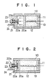
- Figs. 1 and 2 show a thermal switch which represents a first embodiment of the present invention.
- This thermal switch is provided with a tubular heat-conductive case 10, a heat-conductive base plate 11 fixed to one end of the case 10, a movable contact member 20a attached to an intermediate portion of the case 10 so as to be movable in the the axial direction thereof, silicone rubber 12 which fills the space between the heat-conductive base plate 11 and the movable contact member 20a and which forms an elastic solid body which has superior oilproofing, heat resistance, low temperature resistance, electrical insulating, and thermal expansion properties.
- Fig. 3 shows experimental data on the thermal expansion of each product with respect to temperature.
- the ordinate represents expansion (mm) and the abscissa represents temperature (°C).
- each product starts to expand at a temperature within the range of 40 to 50°C and displays an extremely linear increase in expansion with respect to temperature rise above this temperature range.
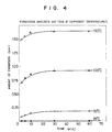
- Fig. 4 shows experimental data on the thermal expansion of KE10 while it is stabilizing with time.
- the ordinate represents expansion (mm) and the absccisa represents time (min.). As will be understood from Fig. 4, it takes 30 to 60 minutes for the material to reach its maximum expansion and, after this period of time, the material is in an equilibrium state.
- One end of a lead wire 13 which is capable of expanding and contracting is connected to the surface of the movable contact member 20a facing the base plate 11 and the wire is led to the outside through the base plate 11.
- a fixed contact member 20b which is disposed at the other end of the case 10 is constituted by an electrically conductive flat plate 21 fixed to the case 10, and an electrically conductive screw 22 which is screwed through the flat plate 21 and which has a conductive contact piece 22a attached to its top end facing the movable contact member 20a.
- One end of a lead wire 24 is connected to the outer surface of the flat plate 21.
- the heat-conductive base plate 11, the silicone rubber 12 and the heat-conductive case 10 constitute a heat sensing unit, and the movable contact member 20a and the fixed contact member 20b constitute an operation unit which acts as a switching device.
- the operation of the first embodiment of the present invention will be described below with reference to Figs. 1 and 2.
- the silicone rubber 12 gradually expands.
- the movable contact member 20a moves toward the fixed contact 20b and is pressed against the contact piece 22a of the fixed contact 20b, thereby turning on the thermal switch.
- the temperature of the silicone rubber 12 also decreases so that the silicone rubber 12 contracts and disconnects the movable contact member 20a from the contact piece 22a of the fixed contact 20b, thereby turning off the thermal switch.
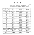
- Fig. 5 shows the results of a repetitive operation test in which three thermal switches of the above-described construction incorporating fillings of silicone rubber KE10 were operated 10 times at a set temperature of 60°C.
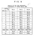
- Fig. 6 shows the results of another repetitive operation test in which three thermal switches of the above-described construction incorporating fillings of silicone rubber KE10 were operated 10 times at a set temperature of 65°C.
- the difference between the maximum operating temperature and the minimum operating temperature is small and desirable values of average (x) and standard deviation ( ⁇ n-1 ) were obtained, ensuring improved reproducibility and accuracy.
- the thermal switch it is possible to make the thermal switch operate at a lower set temperature by tightening the screw 22 constituting the fixed contact member 20b so as to bring the contact piece 22a closer to the movable contact member 20a, and it is similarly possible to make the thermal switch operate at a higher temperature by unscrewing the screw 22 from the plate and moving the contact piece 22a away from the movable contact 20a.
- this thermal switch can be reduced in size since it is possible to freely change its shape and size by adjusting the amount of silicone rubber 12 enclosed in it, and it can easily be handled during transportation or manufacture since the properties of silicone rubber are stable.
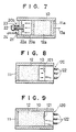
- Fig. 7 shows a second embodiment of the present invention which is provided with silicone rubber 12a which is electrically conductive and thermally expansive, and which fills the space formed between a base plate 11a made of a thermally and electrically conductive material and a movable contact member 20a.
- One end of a lead wire 3a is connected to the other surface of the base plate 11a.
- the end of the lead wire 13a is connected to the outer surface of the base plate 11a, it is possible to easily repair any imperfect contact of the lead wire 13a such as that due to a break in the wire.
- the thermal switch in accordance with the present invention can be reduced in size and weight and can therefore be used by being incorporated in, for example, a calendar, a clock, a picture, and so forth.
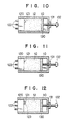
- FIGs. 8 and 9 show a third embodiment of the present invention in which the same components as those in the above embodiments are indicated by the same reference numerals.
- This arrangement also has a tubular heat-conductive case 10, and a heat-conductive base plate 11 is connected to one end of the heat-conductive case 10.
- the heat-conductive case 10 is filled with silicone rubber 12 which has the above-described characteristics and which is supported by the base plate 11.
- a microswitch 120 which serves as an operation unit is attached to the other end of the heat-conductive case 10.
- the microswitch 120 has an actuator, e. g., a pushbutton which is located within the range of expansion of the silicone rubber 12, and terminals 122.
- the moving section of the thermal switch includes no mechanically moving parts, and the silicone rubber 12 having elasticity and thermally expansible and contractible properties is directly brought into contact with and pressed against the pushbutton 121 of the microswitch 120 in a surface-contact manner so that the contacts in the body of the microswitch is separated form the silicone rubber, thereby preventing any imperfect contact and ensuring positive operation of the thermal switch.
- Figs. 10 and 11 are cross-sectional views which illustrate a part of a fourth embodiment of the present invention and in which the same components as those in the above described embodiments are indicated by the same reference numerals.
- This arrangement has a heat-conductive case 10 whose one end is closed and whose other end is opened, and silicone rubber 12 of the above-described type which fills a space in the case 10 so as to cover an actuator of a microswitch to be described later and the surface thereof in which the actuator is disposed.
- This arrangement also has a pushing plate 130 adapted to apply pressing force to the silicone rubber 12, a nut 131 fixed to the outside of the close end of the case 10, an adjusting screw 132 which is adapted for changing the pressing force of the pushing plate 130 and which passes through the case 10 and is screwed into the nut 131.
- One end of the screw 132 is in contact with the pushing plate 130.
- the pushing plate 130, the nut 131 and the adjusting screw 132 constitute a pressurizing unit.
- a switching device 120 e. g., a microswitch is fixed to the open end of the case 10.
- the microswitch 120 has an actuator 120, e. g., a pushbutton 121, and terminals 122.
- the silicone rubber 12 fills the space which is formed between the pushing plate 130 and the microswitch 120.
- the pushing plate 130 moves in the direction of approach to the microswitch 120, that is, it moves so as to increase the pressing force applied to the silicone rubber 12, and the silicone rubber 12 which has a certain degree of rubber elasticity can press the pushbutton 121 of the microswitch 120 at a pressure lower enough to evade the on state of the microswitch 120. It is therefore possible to actuate the thermal switch at a low set temperature.
- the pushing plate 130 moves in the direction of detachment from the microswitch, that is, it moves so as to weaken the pressing force applied to the silicone rubber 12, and the silicone rubber 12 acts to reduce the pressure which has been applied to the pushbutton 121, thereby enabling the thermal switch to be actuated at a high set temperature.
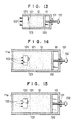
- a fifth embodiment of the present invention will now be described below with reference to Figs. 12 and 13.
- the former has a space 123 which is formed in the silicone rubber along the outer periphery of the pushbutton 121 of the microswitch 120.
- the silicone rubber 12 expands in the manner of cubical expansion, and the space 123 formed in the silicone rubber 12 thereby contracts so that the silicone rubber 12 is gradually brought close to and pressed against the pushbutton 121 of the microswitch 120, thereby turning on the microswitch 120.
- the temperature of the silicone rubber 120 also decreases and, therefore, the silicone rubber 12 contracts in the direction of detachment from the pushbutton 121 of the microswitch 120 so as to gradually form the space 123, thereby turning off the microswitch 120.
- the fifth embodiment is designed to provide the above-described space 123, thereby enabling a wide range of change in temperature.
- Other constructions, operations and effects are the same as those in the first embodiment.
- Figs. 14 and 15 show another possible arrangement in which the microswitch 120 is fixed in an internal space of the case 10 which is closed by a heat-conductive base plate 11a at the opposite end.
- the microswitch 120 can be operated by silicone rubber 12 which encircles the microswitch and fills the internal space of the case 10.
- the adjusting screw enables the pushing plate 130 to be completely closely into contact with the silicone rubber 12 so that no gap is formed between the microswitch 120 and the silicone rubber 12 or between the case 10 and the silicone rubber 12 during the time when the silicone rubber expands. Therefore, the silicone rubber 12 positively and directly presses the pushbutton 121 of the microswitch 120 at a set temperature, thereby ensuring that the thermal switch can operate with a high degree of accuracy. It is also possible to select the set value of the sensing temperature by turning the adjusting screw so as to change the pressing force applied from the pushing plate 130 to the silicone rubber 12.
- a pair of terminals may be provided at one end of the case 10 while disposing an elastic and electrically-conductive contact piece in a position spaced apart from these terminals so that the pair of terminals can be electrically connected when the contact piece is bent by virtue of the expansion of the silicon rubber.
Landscapes
- Physics & Mathematics (AREA)
- Thermal Sciences (AREA)
- Push-Button Switches (AREA)
- Thermally Actuated Switches (AREA)
Applications Claiming Priority (6)
| Application Number | Priority Date | Filing Date | Title |
|---|---|---|---|
| JP1090/87 | 1986-07-11 | ||
| JP18504486U JPS6389652U (de) | 1986-12-02 | 1986-12-02 | |
| JP185044/86U | 1986-12-02 | ||
| JP19983286U JPS63106038U (de) | 1986-12-27 | 1986-12-27 | |
| JP199832/86U | 1986-12-27 | ||
| JP109087A JPS6324519A (ja) | 1987-01-08 | 1987-01-08 | 温度スイツチ |
Related Child Applications (2)
| Application Number | Title | Priority Date | Filing Date |
|---|---|---|---|
| EP93100543.3 Division-Into | 1987-07-10 | ||
| EP19930100543 Division EP0540500A3 (en) | 1986-12-02 | 1987-07-10 | Temperature sensor |
Publications (2)
| Publication Number | Publication Date |
|---|---|
| EP0252523A2 true EP0252523A2 (de) | 1988-01-13 |
| EP0252523A3 EP0252523A3 (de) | 1990-02-07 |
Family
ID=27274758
Family Applications (2)
| Application Number | Title | Priority Date | Filing Date |
|---|---|---|---|
| EP87110021A Withdrawn EP0252523A3 (de) | 1986-07-11 | 1987-07-10 | Temperaturfühler |
| EP19930100543 Withdrawn EP0540500A3 (en) | 1986-12-02 | 1987-07-10 | Temperature sensor |
Family Applications After (1)
| Application Number | Title | Priority Date | Filing Date |
|---|---|---|---|
| EP19930100543 Withdrawn EP0540500A3 (en) | 1986-12-02 | 1987-07-10 | Temperature sensor |
Country Status (2)
| Country | Link |
|---|---|
| US (2) | US4893945A (de) |
| EP (2) | EP0252523A3 (de) |
Cited By (1)
| Publication number | Priority date | Publication date | Assignee | Title |
|---|---|---|---|---|
| CN109559941A (zh) * | 2018-11-09 | 2019-04-02 | 天津航空机电有限公司 | 一种气动式温度继电器 |
Families Citing this family (6)
| Publication number | Priority date | Publication date | Assignee | Title |
|---|---|---|---|---|
| US5736919A (en) * | 1996-02-13 | 1998-04-07 | Cooper Industries, Inc. | Spiral wound fuse having resiliently deformable silicone core |
| DE19609203A1 (de) * | 1996-03-09 | 1997-09-11 | Urich Manfred | Mechanisch-elektrisches Kombinationsthermometer |
| EP2159580B1 (de) * | 2008-08-26 | 2015-10-07 | Lake Shore Cryotronics, Inc. | Sondenspitze |
| CN104241020B (zh) * | 2013-06-07 | 2016-08-24 | 中国科学院理化技术研究所 | 用于耦合低温制冷机与被冷却器件的杠杆式低温热开关 |
| FR3041719B1 (fr) * | 2015-09-25 | 2017-10-20 | Schneider Electric Ind Sas | Dispositif de surveillance de la temperature et du serrage d'une vis |
| EP4786895A1 (de) * | 2025-01-31 | 2026-08-05 | Siemens Healthcare Limited | Thermischer schalter, kryogenes system und magnetresonanzvorrichtung |
Family Cites Families (18)
| Publication number | Priority date | Publication date | Assignee | Title |
|---|---|---|---|---|
| US1416851A (en) * | 1918-01-23 | 1922-05-23 | Mcneil Alfred Henry | Thermostatic regulating or controlling apparatus |
| US1774801A (en) * | 1927-03-29 | 1930-09-02 | Macke Jacob | Pressure-operated multiple-circuit switch |
| US2390948A (en) * | 1943-10-25 | 1945-12-11 | Chicago Flexible Shaft Co | Compensating thermostat |
| US2755349A (en) * | 1952-04-10 | 1956-07-17 | Clem H Silvers | Time delay mechanism |
| US2990716A (en) * | 1958-11-04 | 1961-07-04 | Texas Instruments Inc | Thermally responsive actuator |
| US3040581A (en) * | 1959-12-24 | 1962-06-26 | Gen Controls Co | Means and techniques for sensing and controlling temperatures |
| DE1193577B (de) * | 1960-02-17 | 1965-05-26 | Standard Thomson Corp | Durch Strombeheizung und Volumenaenderung betaetigbare Steuervorrichtung, z. B. fuer elektrische Schalter |
| US3143618A (en) * | 1960-06-11 | 1964-08-04 | Platen Baltzar Carl Von | Thermally responsive electric circuit breaker |
| GB1106515A (en) * | 1965-10-29 | 1968-03-20 | Maclaren Controls Ltd | Improvements in or relating to thermostats |
| DE1959229C3 (de) * | 1968-07-19 | 1978-12-21 | Israel Aircraft Industries, Ltd., Lod Airport (Israel) | Durch plötzliche Bewegung eines äußeren Glieds betätigbarer elektrischer Schalter mit einem fließfähigen Material |
| US4295699A (en) * | 1969-09-15 | 1981-10-20 | Essex International, Inc. | Pressure sensitive combination switch and circuit breaker construction |
| IL42470A (en) * | 1973-06-11 | 1976-01-30 | Israel Aircraft Ind Ltd | A circuit breaker that responds to sudden movements |
| DE2354205A1 (de) * | 1973-10-30 | 1975-05-15 | Bbc Brown Boveri & Cie | Elektrischer temperaturschalter |
| US4155062A (en) * | 1977-09-22 | 1979-05-15 | Essex Group, Inc. | Thermally sensitive electrical switch |
| FR2416539A1 (fr) * | 1978-02-02 | 1979-08-31 | Alsthom Cgee | Bouton-poussoir de commande d'un organe de contact |
| US4541735A (en) * | 1984-12-24 | 1985-09-17 | General Motors Corporation | Thermal sensing element using methanol saturated fluorocarbon elastomer as the heat responsive material |
| DE3540414A1 (de) * | 1985-11-14 | 1987-05-21 | Ego Elektro Blanc & Fischer | Temperaturbegrenzer |
| US4742189A (en) * | 1986-12-12 | 1988-05-03 | Piezo Electric Products, Inc. | Visco-elastic delayed actuator |
-
1987
- 1987-07-10 US US07/072,206 patent/US4893945A/en not_active Expired - Fee Related
- 1987-07-10 EP EP87110021A patent/EP0252523A3/de not_active Withdrawn
- 1987-07-10 EP EP19930100543 patent/EP0540500A3/en not_active Withdrawn
-
1988
- 1988-09-09 US US07/242,384 patent/US4963851A/en not_active Expired - Fee Related
Cited By (1)
| Publication number | Priority date | Publication date | Assignee | Title |
|---|---|---|---|---|
| CN109559941A (zh) * | 2018-11-09 | 2019-04-02 | 天津航空机电有限公司 | 一种气动式温度继电器 |
Also Published As
| Publication number | Publication date |
|---|---|
| EP0540500A2 (de) | 1993-05-05 |
| EP0540500A3 (en) | 1993-05-19 |
| US4893945A (en) | 1990-01-16 |
| EP0252523A3 (de) | 1990-02-07 |
| US4963851A (en) | 1990-10-16 |
Similar Documents
| Publication | Publication Date | Title |
|---|---|---|
| GB2126421A (en) | A thermal switch | |
| US2990716A (en) | Thermally responsive actuator | |
| US4963851A (en) | Temperature sensor | |
| US5181005A (en) | Thermal switch | |
| US2759066A (en) | Temperature responsive switch | |
| US3330925A (en) | Snap-acting pressure switch | |
| US3893057A (en) | Sealed thermostatic switch | |
| CN1039515C (zh) | 热保护器 | |
| US2520660A (en) | Pressure switch | |
| US4479039A (en) | Electrical switch construction and method of making the same | |
| US3275773A (en) | Over-center snap switch | |
| US4135177A (en) | Thermal protective switch | |
| US3043937A (en) | Electrical control means | |
| US2824933A (en) | Miniature switch | |
| US4155062A (en) | Thermally sensitive electrical switch | |
| US3117205A (en) | Rod-in-tube actuated temperature sensing device | |
| US3386066A (en) | Switch having simplified structural features | |
| JPS6324519A (ja) | 温度スイツチ | |
| US3530419A (en) | Thermostat | |
| US3365557A (en) | Pressure responsive diaphragm operated device | |
| US2810041A (en) | Thermostatic device | |
| JPH0195430A (ja) | 温度スイッチ | |
| US3562690A (en) | Snap-acting thermostatic element and method for making same | |
| US4536736A (en) | Thermostat | |
| US4941254A (en) | Method for producing a motion transmitting and amplifying device |
Legal Events
| Date | Code | Title | Description |
|---|---|---|---|
| PUAI | Public reference made under article 153(3) epc to a published international application that has entered the european phase |
Free format text: ORIGINAL CODE: 0009012 |
|
| AK | Designated contracting states |
Kind code of ref document: A2 Designated state(s): DE FR GB IT |
|
| PUAL | Search report despatched |
Free format text: ORIGINAL CODE: 0009013 |
|
| AK | Designated contracting states |
Kind code of ref document: A3 Designated state(s): DE FR GB IT |
|
| 17P | Request for examination filed |
Effective date: 19900711 |
|
| 17Q | First examination report despatched |
Effective date: 19920603 |
|
| STAA | Information on the status of an ep patent application or granted ep patent |
Free format text: STATUS: THE APPLICATION IS DEEMED TO BE WITHDRAWN |
|
| 18D | Application deemed to be withdrawn |
Effective date: 19940202 |
|
| RIN1 | Information on inventor provided before grant (corrected) |
Inventor name: NAGATA, TONOMI Inventor name: OKANO, TERUO |