EP0252570A2 - Véhicule polyvalent et appareil de direction pour celui-ci - Google Patents
Véhicule polyvalent et appareil de direction pour celui-ci Download PDFInfo
- Publication number
- EP0252570A2 EP0252570A2 EP87201306A EP87201306A EP0252570A2 EP 0252570 A2 EP0252570 A2 EP 0252570A2 EP 87201306 A EP87201306 A EP 87201306A EP 87201306 A EP87201306 A EP 87201306A EP 0252570 A2 EP0252570 A2 EP 0252570A2
- Authority
- EP
- European Patent Office
- Prior art keywords
- vehicle
- wheels
- computer
- hydraulic
- steering
- Prior art date
- Legal status (The legal status is an assumption and is not a legal conclusion. Google has not performed a legal analysis and makes no representation as to the accuracy of the status listed.)
- Withdrawn
Links
- 230000033001 locomotion Effects 0.000 claims abstract description 5
- 239000003921 oil Substances 0.000 claims description 28
- 230000000712 assembly Effects 0.000 claims description 23
- 238000000429 assembly Methods 0.000 claims description 23
- 239000012530 fluid Substances 0.000 claims description 18
- 238000000034 method Methods 0.000 claims description 17
- 230000001105 regulatory effect Effects 0.000 claims description 11
- 230000008859 change Effects 0.000 claims description 7
- 238000004891 communication Methods 0.000 claims description 5
- 239000010720 hydraulic oil Substances 0.000 claims description 2
- 230000000694 effects Effects 0.000 claims 1
- 230000033228 biological regulation Effects 0.000 abstract description 3
- 230000005540 biological transmission Effects 0.000 description 7
- 239000000446 fuel Substances 0.000 description 4
- 230000002457 bidirectional effect Effects 0.000 description 3
- 238000000926 separation method Methods 0.000 description 3
- 238000010586 diagram Methods 0.000 description 2
- 230000008569 process Effects 0.000 description 2
- 239000002699 waste material Substances 0.000 description 2
- 238000006243 chemical reaction Methods 0.000 description 1
- 238000010276 construction Methods 0.000 description 1
- 230000003247 decreasing effect Effects 0.000 description 1
- 230000002262 irrigation Effects 0.000 description 1
- 238000003973 irrigation Methods 0.000 description 1
- 230000003287 optical effect Effects 0.000 description 1
- 230000004044 response Effects 0.000 description 1
Images




Classifications
-
- B—PERFORMING OPERATIONS; TRANSPORTING
- B62—LAND VEHICLES FOR TRAVELLING OTHERWISE THAN ON RAILS
- B62D—MOTOR VEHICLES; TRAILERS
- B62D7/00—Steering linkage; Stub axles or their mountings
- B62D7/06—Steering linkage; Stub axles or their mountings for individually-pivoted wheels, e.g. on king-pins
- B62D7/14—Steering linkage; Stub axles or their mountings for individually-pivoted wheels, e.g. on king-pins the pivotal axes being situated in more than one plane transverse to the longitudinal centre line of the vehicle, e.g. all-wheel steering
- B62D7/15—Steering linkage; Stub axles or their mountings for individually-pivoted wheels, e.g. on king-pins the pivotal axes being situated in more than one plane transverse to the longitudinal centre line of the vehicle, e.g. all-wheel steering characterised by means varying the ratio between the steering angles of the steered wheels
- B62D7/1509—Steering linkage; Stub axles or their mountings for individually-pivoted wheels, e.g. on king-pins the pivotal axes being situated in more than one plane transverse to the longitudinal centre line of the vehicle, e.g. all-wheel steering characterised by means varying the ratio between the steering angles of the steered wheels with different steering modes, e.g. crab-steering, or steering specially adapted for reversing of the vehicle
Definitions
- the present invention relates to vehicles, such as tractors, which are operative in a plurality of modes, such as highway mode and off-highway mode, and to steering apparatus and computer controlled systems therefor.
- tractors should be designed to have a relatively wide wheelbase in order to enable them to carry out a given function over a field in a minimum number of traversals, thereby saving time and fuel and reducing the damage to crops due to traversal of the tractor as well as reducing the number of tractor traversable separations between crops. Further advantages, such as non-interference with irrigation conduits and the like, may also be appreciated.
- a concomitant requirement in the design of a tractor is that it be capable of self-propulsion over the highway transport. It may be appreciated that, due to its wheelbase, a tractor of the design described hereinabove could not travel along a highway of the same wheelbase. It is thus necessary to orient the tractor along a narrower profile for highway transport.
- a further important design principle requires that a tractor be capable of a 180 degree turn about a pivot axis defined by one of its wheels, so as to enable the tractor to turn at the end of a row and return along an adjacent row with the pivot wheel in the same channel.
- An additional principle of design requires that a tractor be capable of a full turn about a pivot axis defined by its geometric center, or by the mid-point of an imaginary line joining two wheels along the narrower wheelbase.
- a further important design feature of tractors is that of efficient power transmission for agricultural machinery connected thereto and powered thereby.
- a measure of power required by machinery is the number of Revolutions Per Minute (RPM) of its motor or of other similar motive apparatus.
- the present invention seeks to provide a vehicle having the capabilities described hereinabove, steering apparatus for such a vehicle and an advanced system of hydraulic power transmission to additional machinery powered by such a vehicle.
- steering apparatus for a vehicle such as a tractor and comprising first, second, third and fourth wheels pivotably and rotatably mounted onto a chassis, positioning apparatus associated with the first, second, third and fourth wheels including first positioning apparatus for selectably positioning all of the wheels in first and second extreme positions and second positioning apparatus associated with the second and third wheels, and operative when the first and fourth wheels are in the second extreme position for providing steering of the second and third wheels.
- the first and second positioning apparati comprise fluid operated pistons.
- the first, second, third and fourth wheels are pivotably mounted at vertices of an imaginary rectangle whereby the first and second wheels are separated by a first distance, the third and fourth wheels are separated by the first distance, the second and third wheels are separated by a second distance, and the first and fourth wheels are separated by the second distance.
- the first distance is selected to be larger than the second distance and to represent the wheelbase of the vehicle for off-highway operation and the second distance is selected to be the wheelbase of the vehicle for highway operation.
- the first and second wheels are selected to be at the leading end of the vehicle for off-highway operations and the second and third wheels are selected to be at the leading end of the vehicle for highway operations.
- the first positioning apparatus comprises first, second, third and fourth fluid operated piston and cylinder assemblies associated with the first, second, third and fourth wheels respectively for providing selectable pivotal positioning thereof.
- the first and second piston and cylinder assemblies each comprise two pistons arranged in back-to-back relationship for individual series operation in providing predetermined angled positioning of the first and second wheels. All of the piston assemblies are provided with a maximum stroke which produces a 90 degree rotation in the orientation of the associated wheel.
- the second positioning apparatus comprises a bi-directional piston assembly, which is coupled at opposite ends thereof to the second and third piston and cylinder assemblies in a series arrangement with each of them separately.
- each of the four wheels is provided with an individual hydraulic wheel motor.
- the first and fourth wheel motors are associated with a first variable hydraulic pump, while the second and third wheel motors are associated with a second variable hydraulic pump. Fluid communication between the first and second hydraulic pumps is permitted for highway mode operation but is prevented for off-highway mode operation other than during turning.
- Apparatus is also provided for supplying all of the hydraulic fluid power to a selected pair of wheels during highway mode operation.
- the third and fourth wheels are provided with brake apparatus for securing a wheel in fixed orientation when it defines a pivot location during turning operation.
- a computerized steering system comprising: a computer; a plurality of hydraulic valves, each of which is adapted to respond to computer signals; a plurality of angular resolvers, each of which is located on a wheel and is adapted to "read" the angle of pitch of that wheel and to feed that information to the computer; and a plurality of hydraulic pistons, each of which is associated with a wheel and which is activated by one of the hydraulic valves.
- the computer is adapted to receive a turning instruction from an operative, whereupon the computer will check the pitch of each of the wheels by means of the angular resolvers, and send an instruction, in accordance with the information received, to the valve, thus releasing a quantity of hydraulic oil under pressure to the piston such that the wheels are turned in accordance with the original turning instruction.
- a steering wheel is provided, which is adapted to pass turning instructions from the operative to the computer.
- each of the plurality of angular resolvers comprises apparatus including a potentiometer.
- the computer is additionally adapted to comprise part of a system which regulates the hydraulic power that a tractor is operative to supply, by way of a power take off transmission system, to a piece of hydraulically powered machinery connected thereto, which power supply is directly related to the rate of revolutions of an hydraulic motor to which the power take off is connected, and which regulating system additionally comprises: a variable output oil pump, which supplies oil to the hydraulic motor and which is connected to the computer; a diesel engine, to which the oil pump is connected; and a speed gauge, which measures the speed of advance of the tractor along the ground.
- a thumbwheel is provided, which is adapted to pass instructions from the operative to the computer.
- a method of regulating the supply of hydraulic power that the tractor is operative to supply to hydraulically powered machinery connected thereto, which power supply is directly related to the rate of revolutions of an hydraulic motor comprises the steps of: manually adjusting a thumbwheel, associated with a computer, according to a desired rate of revolutions per minute (RPM) needed to power the hydraulic machinery connected to the tractor; the computer, being associated additionally with the Power Take Off (PTO) of the tractor, "reading" the actual rate of RPM and comparing the actual rate with that indicated by the thumbwheel, sending a signal to a variable output oil pump, with which it is further associated, to accordingly increase or decrease its rate of oil supply to an hydraulic motor connected to the PTO; and a diesel engine, associated with the oil pump, adjusting its RPM according to the total amount needed for the running of the tractor and of the agricultural machinery connected thereto.
- RPM revolutions per minute
- a method of regulating the supply of hydraulic power that the tractor is operative to supply to hydraulically powered machinery connected thereto, which power supply is directly related to the rate of revolutions of an hydraulic motor comprises the steps of: an operative rotating and setting a thumbwheel, associated with a computer, according to a desired speed of forward advance of the tractor, and corresponding to a desired rate of revolutions per minute (RPM) of the Power Take Off (PTO) of a tractor; the computer, being associated additionally with the PTO, "reading” the present speed of the tractor and comparing the present speed with that indicated by the thumbwheel, sending a signal to a variable output oil pump, with which it is further associated, to accordingly increase or reduce its rate of oil supply to an hydraulic motor connected to the PTO; and a diesel engine, associated with the oil pump, adjusting its speed according to that originally set by the operative.
- RPM revolutions per minute
- FIGs. 1A - 1C illustrate a tractor constructed and operative in accordance with an embodiment of the present invention and comprising a body 10 which is mounted on a chassis 12.
- Body and chassis together define a front end 14 for off-highway operations and a front end 16 for highway operations.
- suitable steering and other controls 18 for both on and off-highway modes of operation.
- highway and off-highway are used to denote distinct modes of operation.
- highway mode operation it is meant movement of the vehicle on a road or in any other application wherein a narrow wheelbase profile is required.
- off-highway mode operation it is meant any application other that the above highway application, where the wide-wheelbase profile is desirable, such as for fieldwork.
- the steering apparatus comprises first, second, third and fourth wheels 20, 22, 24 and 26 respectively, each of which is independently pivotably and rotatably mounted onto chassis 12 about respective pivot axes 28, 30, 32 and 34.
- Axes 28, 30, 32 and 34 are preferably arranged at the vertices of a rectangle such that the separation between axes 28 and 30 is greater than the separation between axes 28 and 34.
- positioning apparatus including first positioning apparatus comprising four individual piston and cylinder assemblies 36, 38, 40 and 42, associated with respective wheels 20, 22, 24 and 26, and which are fluid operated preferably hydraulically for selectably positioning the individual wheels.
- first positioning apparatus comprising four individual piston and cylinder assemblies 36, 38, 40 and 42, associated with respective wheels 20, 22, 24 and 26, and which are fluid operated preferably hydraulically for selectably positioning the individual wheels.
- Alternative types of linear positioning apparatus such as, for example, screw drives, may also be used.
- Piston and cylinder assemblies 36 and 38 are typically similar and each comprises a piston assembly including first and second pistons 44 and 46 arranged in back-to-back orientation for series operation in response to separate control inputs.
- piston and cylinder assemblies 36 and 38 are used to enable pivotable turning of the tractor about a fixed pivot axis coincident with either of axes 32 and 34.
- the ratio of the strokes of the two pistons is functionally related to the ratio of the distance separating wheels 20 and 22 to that separating wheels 20 and 26.
- Piston and cylinder assemblies 40 and 42 are typically similar and each comprises a single stage piston whose stroke is operative to provide a 90 degree rotation of its associated wheel.
- Each of the piston and cylinder assemblies is coupled at one end via a connecting rod to its corresponding wheel for selectable positioning thereof.
- Assemblies 36 and 42 are pivotably coupled at their opposite ends to a fixed location in chassis 12.
- a second positioning apparatus comprising a bidirectional fluid operated cylinder and piston combination 50 having a piston 52 to which are coupled piston and cylinder assemblies 38 and 40, instead of being attached to a fixed location as are assemblies 36 and 42.
- the operation of the second positioning apparatus will be described hereinafter in connection with Figs. 3a and 3B.
- steering may be provided on all four wheels, individually, or as a further alternative on any pair of adjacent wheels.
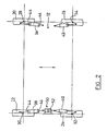
- Fig. 2 shows the wheels of the vehicle oriented for operation in an off-highway mode with a wide wheelbase profile. All of piston and cylinder assemblies 36, 38, 40, and 42 are fully extended. Steering in this mode is provided by suitable differential operation of hydraulic fluid pumps which power motors associated with each of the wheels. The motive system will be described herinafter in connection with Fig. 6.
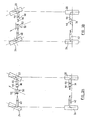
- Figs. 3A and 3B illustrate the vehicle of Figs. 1A - 1C and Fig. 2 having its wheels oriented for highway mode operation with a narrow wheelbase profile.
- Cylinder and piston assemblies 40 and 42 are both in their fully retracted orientations, while cylinder and piston assemblies 36 and 38 are partially retracted, having pistons 44 retracted and pistons 46 extended.
- Steering of the vehicle in the highway mode is provided solely by bidirectional piston and cylinder combination 50 which positions the piston and cylinder assemblies 38 and 40 in accordance with the position of piston 52.
- Fig 3A illustrates combination 50 with piston 52 in an extreme left orientation with respect to the direction of travel, thus producing steering to the extreme left.
- conversion of the vehicle from operation in one mode to operation in the other mode is simply effected by suitable operation of the piston and cylinder assemblies and does not require motion of the vehicle.
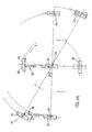
- FIGs. 4A and 4B illustrate the technique whereby the vehicle may be turned about a fixed pivot defined at one of its wheels. Such precise and low radius turning is particularly useful for operation at the end of a row in a field, which it is desired to resume operation in the opposite direction in an adjacent row with the pivot wheel in the same channel.
- Fig. 4A illustrates clockwise rotation
- Fig. 4B illustrates counterclockwise rotation.
- each of the wheels is arranged to lie in a plane perpendicular to the imaginary line connecting its pivot axis to the axis about which vehicle rotation is desired, in thise case, axis 34. It may thus be appreciated that wheel 24 stays in its off-highway mode orientation.
- Wheel 20 is shifted to its highway mode orientation, as seen in Figs. 3A and 3B, by partial retraction of piston and cylinder assembly 36.
- Wheel 22 is moved to an orientation intermediate its extreme orientations by retraction of piston 46 and extension of piston 44 of assembly 38.
- the precise angle of orientation of wheel 22 is determined by the ratio of the lengths of the sides of the rectangle along whose vertices are located the pivot axes of the individual wheels. In a typical case, where the distance between axes 28 and 30 is 5.8 meters and the distance between axes 28 and 34 is 3.0 meters, the wheel 22 is oriented at approximately 27 degrees with respect to the axis connecting axes 30 and 32.
- the orientations of the individual wheels for turning about axis 34 are illustrated in Fig. 4A.
- wheels 20, 22, and 24 By providing power to wheels 20, 22, and 24, the orientation of the vehicle is rotated from that shown in the upper left quadrant of Fig. 4A to that shown in solid lines in the lower right quadrant of Fig. 4A. Following this rotation, wheels 20 and 22 may be reoriented to their Fig. 2 off-highway mode positions as illustrated in dotted lines, and work of the vehicle can resume in an opposite direction along an adjacent axis with the pivot wheel in the same channel.
- Fig. 4B illustrates counterclockwise rotation about axis 32.
- wheel 20 is provided with a desired angled orientation by retraction of piston 46 and extension of piston 44 of assembly 36, while wheel 22 is oriented in its highway mode orientation by extension of piston 46 and retraction of piston 44 of assembly 38.
- Wheel 26 stays in its off-highway mode orientation. The remainder of the rotation is clear from the above description of clockwise rotation with reference to Fig. 4A.
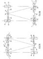
- FIGs. 5A, 5B and 5C illustrate the technique whereby the vehicle may be turned in either a clockwise or counterclockwise direction about a fixed pivot defined at points located halfway between axes 28 and 34, halfway between axes 30 and 32 and at its geometric center, denoted respectively by reference numerals 92, 94 and 96. Turning about any of these three points may be performed when it is desired to totally reverse the direction of travel.
- the vehicle which, by way of example may be considered to have started in a highway mode of operation, in order to carry out a turn about pivot point 92, located at rear end 15, maintains back wheels 20 and 26 in a highway alignment, and by suitable operation of the piston assemblies, each of wheels 22 and 24 is arranged to lie in a plane perpendicular to the imaginary line connecting their respective pivot axes to the point about which vehicle rotation is desired.
- Wheels 22 and 24 are moved to orientations between their extreme orientations by partial retraction of piston 46 and extension of piston 44 of assembly 38, and by partial retraction of piston and cylinder assembly 40.
- the precise angles of orientation of wheels 22 and 24 are determined by the ratio of lengths of the sides of the triangle defined by vertices located at points 30, 32 and 92.
- wheels 22 and 24 are oriented at 14.5 degrees approximately, with respect to the axis connecting axes 30 and 32.
- the orientations of the individual wheels for turning about pivot point 92 are illustrated in Fig. 5A.
- the orientation of the vehicle is rotated from that shown in Fig. 5A to any required position wherein point 92 is fixed and wheels 22 and 24 lay on a circle defined by their rotation about that point.
- Fig. 5B illustrates rotation about pivot point 94 located halfway between axes 30 and 32 at front end 16 of the vehicle.
- wheels 20 and 26 are provided with a desired angled orientation by partial retraction of piston 46 and extension of piston 44 of assembly 36, and and by partial extension of piston and cylinder assembly 42, while wheels 22 and 24 remain in highway mode orientation.
- the remainder of the rotation is clear from the above description of rotation with reference to Fig. 5A.
- Fig. 5C illustrates rotation about pivot point 96 located at the geometric center of the vehicle.
- each of the four wheels 20, 22, 24 and 26 is arranged to lie in a plane perpendicular to the imaginary line connecting their respective pivot axes to the point about which vehicle rotation is desired.
- Each of the wheels 20, 22, 24 and 26 is moved to an orientation between its extreme orientation by respective retraction of piston 46 and extension of piston 44 of assembly 36, by extension of piston 44 and retraction of piston 46 of assembly 38, by partial retraction of piston and cylinder assembly 40, and by partial retraction of piston and cylinder assembly 42.
- the precise angles of orientation of the wheels are determined by the ratio of lengths of the sides of the triangles defined by vertices located at points 28, 30, 32, 34 and 96.
- the wheels are oriented at approximately 27 degrees with respect to the axes connecting axes 30 and 32, and 28 and 34.
- the orientations of the individual wheels for turning about pivot point 96 are illustrated in Fig. 5C.
- the orientation of the vehicle is rotated from that shown in Fig. 5C to any required position wherein point 96 is fixed and wheels 20, 22, 24 and 26 lay on a circle defined by their rotation about point 96.
- Fig. 6 illustrates hydraulic motive apparatus as well as brake apparatus for a tractor of the type described hereinabove.
- the hydraulic motive system comprises four wheel motors, 60, 62, 64 and 66, each associated with a respective wheel 20, 22, 24 and 26 for driving engagement therewith.
- Motors 60 and 66 are arranged in series with a variable hydraulic pump 68, while motors 62 and 64 are arranged in series with a variable hydraulic pump 70.
- first and second remotely operable valves 72 and 74 govern the supply of hydraulic fluid from pump 70 to motors 62 and 64.
- such valves may be associated additionally or alternatively with motors 60 and 66 and pump 68.
- Third and fourth remotely operable valves 76 and 78 govern hydraulic fluid communication between pumps 68 and 70.
- valves 72 and 74 are closed during highway mode operation, when all the motive power is supplied to the back wheels of the vehicle.
- all of the power may be supplied in such a case to the front wheels, or, as a further alternative, supplied to all of the wheels.
- valves 76 and 78 are normally closed during off-highway operation except during pivot turns, in order to permit steering to be achieved by determining the relative amount of hydraulic fluid supplied to the wheels at the two sides of the vehicle.
- hydraulically operated brake apparatus 80 and 82 are associated with respective wheels 24 and 26.
- control of the operation of the vehicle and of its turning functions is provided by suitable hydraulic controls.
- the controls of the individual pistons and valves is grouped according to function, such that indication of a given function actuates the individual pistons and valves in a desired way. This grouping may be achieved by suitable mechanical, fluidic or electrical logic circuitry.
- valves 84 which lock the bidirectional steering piston 52 in its central position by preventing fluid communication with both sides of the piston 52 in cylinder 50.
- the central position is determined by a suitable optical, mechanical or other indicator 88.
- Steering in the highway mode is provided by a bidirectional steering valve 90.
- the operation of the logic circuitry may be understood by reference to the following truth table which is arranged by function and indicates the operation state of the various valves and pistons, and wherein the following orientations correspond to code letters as follows: OFF HIGHWAY A HIGHWAY B RIGHT TURN (Fig. 4A) C LEFT TURN (Fig. 4B) D REAR TURN (Fig. 5A) E FRONT TURN (Fig. 5B) F CENTER TURN (Fig. 5C) G
- Fig. 7 shows a computer controlled steering system that may be used in conjunction with a preferred embodiment of the present invention.
- Hydraulic piston 102 is associated with a wheel 110, upon which is located an angular resolver 104, which device is sensitive to changes in orientation of the wheel, and may comprise a device such as a potentiometer.
- Valve 100 and resolver 104 are both connected to a computer 106, that is adapted to receive information from resolver 104 concerning the orientation of wheel 110, and which is also adapted to send signals to valve 100 for the operation thereof, which operation changes the orientation of wheel 110 by the operation of piston 102.
- the hereinabove described computerized system is adapted to be incorporated into a steering system, wherein a central computer may control any number of wheels according to instructions from an operative 108, as hereinbelow described.
- Instructions are fed into the computer by operative 108 by turning a steering wheel 109 as in normal steering operations, the particular feature being, that steering wheel 109 used in conjunction with the computerized system of the present invention is connected with computer 106, such that when steering wheel 109 is turned, computer 106 interprets the turn as an instruction to check on the present angular orientation of a wheel by reading information being received from angular resolver 104.
- computer 106 sends a signal for the operation of valve 100 in order to operate piston 102.
- the angle of wheel 110 is again checked, and the above-described sequence of operating valve 100 and rechecking the angle is repeated, until the instruction from operative 108 has been carried out. It will be appreciated by those skilled in the art that the above-described sequence typically takes fractions of a second to be completed.
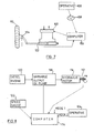
- FIG. 8 shows a block diagram illustration of a system for computer control of a Power Take Off transmission system of a tractor.
- a Power Take Off transmission system (PTO), is used for transferring power to agricultural machinery that is attached to a tractor. It comprises a shaft having longitudinal grooves, and is constructed for engagement with a power transfer point on the machinery.
- the shaft is designed to be rotated at speeds of up to 1200 revolutions per minutes (RPM) and its rotation speed is directly connected to that of a diesel engine powering the tractor, such that if the machinery that is being powered by the tractor needs power to be supplied, for example, at 1200 RPM, even if the tractor engine would otherwise need to turn at a much lower rate, the engine must turn faster, according to the needs of the machinery to which power is being supplied: this obviously causes a great waste of fuel.
- RPM revolutions per minutes
- Fig. 8 a transmission system, that is designed to transfer power to machinery by way of a PTO 112 of a tractor, but which is not linked to the engine speed.
- PTO 112 is connected to an hydraulic motor 116, which is connected to a variable output oil pump 118, which is itself connected to a diesel engine 120. Both PTO 112 and oil pump 118 are connected with a computer 114, to which are also connected to a speed gauge 122, which may typically be calibrated in km/h, and means for an operative 124 to program the computer in either one of two modes of operation, both of which will be described hereinbelow.
- operative 124 may program computer 114 to set PTO 112 to rotate at a particular rate of rotation in RPM. This is done by using means such as a thumbwheel connected to the computer. Once computer 114 has received a command as hereinabove described, it can check the rate of rotation of PTO 112, which, prior to operations, will typically be at rest.
- computer 114 sends a signal to variable output oil pump 118 to correspondingly increase or decrease its supply of oil to hydraulic motor 116, which increase or decrease will immediately cause a commensurate increase or decrease in the speed of rotation of PTO 112.
- operative 124 chooses to fix the rate of rotation of PTO 112 in accordance with the speed of advance of the tractor.
- operative 124 programs computer 114 to a set speed, typically in km/h, and computer 114 then checks speed gauge 122 for agreement with the speed programmed thereinto. If any change in tractor speed is needed, computer 114 sends a signal to oil pump 118 to accordingly change its rate of supply of oil to hydraulic motor 116, which change is accomodated by a change in the speed of diesel engine 120, and which also causes a commensurate change in the rotation speed of PTO 112.
Landscapes
- Engineering & Computer Science (AREA)
- Chemical & Material Sciences (AREA)
- Combustion & Propulsion (AREA)
- Transportation (AREA)
- Mechanical Engineering (AREA)
- Steering-Linkage Mechanisms And Four-Wheel Steering (AREA)
- Non-Deflectable Wheels, Steering Of Trailers, Or Other Steering (AREA)
Applications Claiming Priority (2)
| Application Number | Priority Date | Filing Date | Title |
|---|---|---|---|
| US88418886A | 1986-07-10 | 1986-07-10 | |
| US884188 | 1986-07-10 |
Publications (2)
| Publication Number | Publication Date |
|---|---|
| EP0252570A2 true EP0252570A2 (fr) | 1988-01-13 |
| EP0252570A3 EP0252570A3 (fr) | 1989-08-09 |
Family
ID=25384138
Family Applications (1)
| Application Number | Title | Priority Date | Filing Date |
|---|---|---|---|
| EP87201306A Withdrawn EP0252570A3 (fr) | 1986-07-10 | 1987-07-09 | Véhicule polyvalent et appareil de direction pour celui-ci |
Country Status (2)
| Country | Link |
|---|---|
| EP (1) | EP0252570A3 (fr) |
| AU (1) | AU7539287A (fr) |
Cited By (4)
| Publication number | Priority date | Publication date | Assignee | Title |
|---|---|---|---|---|
| USD344737S (en) | 1992-03-19 | 1994-03-01 | Clark Equipment Company | Self propelled sprayer vehicle |
| GB2504681A (en) * | 2012-08-03 | 2014-02-12 | Buttimer & Company Ltd E | Mobile carrier frame for bulk material handling equipment |
| CN117262003A (zh) * | 2023-10-13 | 2023-12-22 | 徐州徐工农业装备科技有限公司 | 一种双模式转向系统及车辆 |
| CN119636895A (zh) * | 2024-12-25 | 2025-03-18 | 徐州徐工农业装备科技有限公司 | 一种车辆转向液压控制系统及方法 |
Family Cites Families (4)
| Publication number | Priority date | Publication date | Assignee | Title |
|---|---|---|---|---|
| FR2208370A5 (fr) * | 1972-11-29 | 1974-06-21 | Hfm Hohenloher Fahrzeuge | |
| CA1010373A (en) * | 1974-11-20 | 1977-05-17 | Robert W. Larson | 90.degree. steering system |
| CH634000A5 (de) * | 1978-04-17 | 1983-01-14 | Arato Gyoergyi | Fahrzeug mit mindestens drei um eine vertikale achse schwenkbaren raedern. |
| DE3245085A1 (de) * | 1982-12-06 | 1984-06-07 | Kramer-Werke GmbH, 7770 Überlingen | Fahrbares arbeitsgeraet |
-
1987
- 1987-07-09 AU AU75392/87A patent/AU7539287A/en not_active Abandoned
- 1987-07-09 EP EP87201306A patent/EP0252570A3/fr not_active Withdrawn
Cited By (5)
| Publication number | Priority date | Publication date | Assignee | Title |
|---|---|---|---|---|
| USD344737S (en) | 1992-03-19 | 1994-03-01 | Clark Equipment Company | Self propelled sprayer vehicle |
| GB2504681A (en) * | 2012-08-03 | 2014-02-12 | Buttimer & Company Ltd E | Mobile carrier frame for bulk material handling equipment |
| CN117262003A (zh) * | 2023-10-13 | 2023-12-22 | 徐州徐工农业装备科技有限公司 | 一种双模式转向系统及车辆 |
| CN119636895A (zh) * | 2024-12-25 | 2025-03-18 | 徐州徐工农业装备科技有限公司 | 一种车辆转向液压控制系统及方法 |
| CN119636895B (zh) * | 2024-12-25 | 2025-10-24 | 徐州徐工农业装备科技有限公司 | 一种车辆转向液压控制系统及方法 |
Also Published As
| Publication number | Publication date |
|---|---|
| AU7539287A (en) | 1988-01-14 |
| EP0252570A3 (fr) | 1989-08-09 |
Similar Documents
| Publication | Publication Date | Title |
|---|---|---|
| US4823899A (en) | Steering apparatus | |
| DE69815053T2 (de) | Lenksystem | |
| US7853380B2 (en) | Steering system having multiple strategies and variable deadzone | |
| US4318451A (en) | Dual function remote steering control | |
| US2614644A (en) | Tractor steering mechanism | |
| US4893689A (en) | Method and apparatus for steering a motor vehicle | |
| US9101090B2 (en) | Windrower autoguidance hydraulic steering interface | |
| US9120504B2 (en) | Steering linkage interface between steering cylinder and ground drive pump displacement control arms | |
| DE19918882A1 (de) | Verfahren und Vorrichtung zur Bereitstellung eines Steuerunterstützungs- und Antischlupfsystems für hydrostatisch getriebene Fahrzeuge | |
| US2863518A (en) | Motor vehicle equipped with wheels capable of steering substantially through 90 deg.from their straight drive position | |
| KR19980081199A (ko) | 멀티 액슬 차량용 스티어링 시스템 | |
| US20120006603A1 (en) | Steering system and method of steering a machine | |
| CN86108535A (zh) | 机动车的转向制动装置 | |
| CA2164153C (fr) | Systeme de direction pour vehicule de travail et methode de mise en application de ce systeme | |
| US11577796B2 (en) | Auto track alignment and undercarriage swing | |
| CN2665225Y (zh) | 全液压推土机行走控制装置 | |
| US7082361B2 (en) | Electronic speed control system for farm machines | |
| US3380547A (en) | Steering system | |
| US6138782A (en) | Steering responsive power boost | |
| US5013057A (en) | Method of controlling a transport means and a transport means for effecting the method | |
| CA1044992A (fr) | Systeme de guidage a reaction variable | |
| NL8900781A (nl) | Trailerbesturing. | |
| CH634000A5 (de) | Fahrzeug mit mindestens drei um eine vertikale achse schwenkbaren raedern. | |
| US4003447A (en) | Hydraulically powered steering system for a vehicle having multiple steerable wheels | |
| US4805719A (en) | Vehicle |
Legal Events
| Date | Code | Title | Description |
|---|---|---|---|
| PUAI | Public reference made under article 153(3) epc to a published international application that has entered the european phase |
Free format text: ORIGINAL CODE: 0009012 |
|
| AK | Designated contracting states |
Kind code of ref document: A2 Designated state(s): AT BE CH DE ES FR GB GR IT LI LU NL SE |
|
| PUAL | Search report despatched |
Free format text: ORIGINAL CODE: 0009013 |
|
| AK | Designated contracting states |
Kind code of ref document: A3 Designated state(s): AT BE CH DE ES FR GB GR IT LI LU NL SE |
|
| STAA | Information on the status of an ep patent application or granted ep patent |
Free format text: STATUS: THE APPLICATION IS DEEMED TO BE WITHDRAWN |
|
| 18D | Application deemed to be withdrawn |
Effective date: 19900201 |
|
| RIN1 | Information on inventor provided before grant (corrected) |
Inventor name: RON, SHIMON |