EP0252676A2 - Tête d'impression à projection d'encre à aspiration d'air avec une chambre à encre à compartiment unique - Google Patents
Tête d'impression à projection d'encre à aspiration d'air avec une chambre à encre à compartiment unique Download PDFInfo
- Publication number
- EP0252676A2 EP0252676A2 EP87305819A EP87305819A EP0252676A2 EP 0252676 A2 EP0252676 A2 EP 0252676A2 EP 87305819 A EP87305819 A EP 87305819A EP 87305819 A EP87305819 A EP 87305819A EP 0252676 A2 EP0252676 A2 EP 0252676A2
- Authority
- EP
- European Patent Office
- Prior art keywords
- ink
- jet head
- chamber
- ink jet
- orifice
- Prior art date
- Legal status (The legal status is an assumption and is not a legal conclusion. Google has not performed a legal analysis and makes no representation as to the accuracy of the status listed.)
- Withdrawn
Links
Images


Classifications
-
- B—PERFORMING OPERATIONS; TRANSPORTING
- B41—PRINTING; LINING MACHINES; TYPEWRITERS; STAMPS
- B41J—TYPEWRITERS; SELECTIVE PRINTING MECHANISMS, i.e. MECHANISMS PRINTING OTHERWISE THAN FROM A FORME; CORRECTION OF TYPOGRAPHICAL ERRORS
- B41J2/00—Typewriters or selective printing mechanisms characterised by the printing or marking process for which they are designed
- B41J2/005—Typewriters or selective printing mechanisms characterised by the printing or marking process for which they are designed characterised by bringing liquid or particles selectively into contact with a printing material
- B41J2/01—Ink jet
- B41J2/135—Nozzles
- B41J2/14—Structure thereof only for on-demand ink jet heads
- B41J2/14201—Structure of print heads with piezoelectric elements
- B41J2/14298—Structure of print heads with piezoelectric elements of disc type
-
- B—PERFORMING OPERATIONS; TRANSPORTING
- B41—PRINTING; LINING MACHINES; TYPEWRITERS; STAMPS
- B41J—TYPEWRITERS; SELECTIVE PRINTING MECHANISMS, i.e. MECHANISMS PRINTING OTHERWISE THAN FROM A FORME; CORRECTION OF TYPOGRAPHICAL ERRORS
- B41J2/00—Typewriters or selective printing mechanisms characterised by the printing or marking process for which they are designed
- B41J2/005—Typewriters or selective printing mechanisms characterised by the printing or marking process for which they are designed characterised by bringing liquid or particles selectively into contact with a printing material
- B41J2/01—Ink jet
- B41J2/015—Ink jet characterised by the jet generation process
- B41J2/04—Ink jet characterised by the jet generation process generating single droplets or particles on demand
-
- B—PERFORMING OPERATIONS; TRANSPORTING
- B41—PRINTING; LINING MACHINES; TYPEWRITERS; STAMPS
- B41J—TYPEWRITERS; SELECTIVE PRINTING MECHANISMS, i.e. MECHANISMS PRINTING OTHERWISE THAN FROM A FORME; CORRECTION OF TYPOGRAPHICAL ERRORS
- B41J2/00—Typewriters or selective printing mechanisms characterised by the printing or marking process for which they are designed
- B41J2/005—Typewriters or selective printing mechanisms characterised by the printing or marking process for which they are designed characterised by bringing liquid or particles selectively into contact with a printing material
- B41J2/01—Ink jet
- B41J2/135—Nozzles
- B41J2/14—Structure thereof only for on-demand ink jet heads
- B41J2002/14387—Front shooter
-
- B—PERFORMING OPERATIONS; TRANSPORTING
- B41—PRINTING; LINING MACHINES; TYPEWRITERS; STAMPS
- B41J—TYPEWRITERS; SELECTIVE PRINTING MECHANISMS, i.e. MECHANISMS PRINTING OTHERWISE THAN FROM A FORME; CORRECTION OF TYPOGRAPHICAL ERRORS
- B41J2202/00—Embodiments of or processes related to ink-jet or thermal heads
- B41J2202/01—Embodiments of or processes related to ink-jet heads
- B41J2202/02—Air-assisted ejection
Definitions
- This invention relates to ink jet heads for ink jet printers, and in particular to an air assisted drop-on-demand ink jet head with a single compartment ink chamber.
- Ink jet printers having one or more ink jet heads for projecting drops of ink onto paper or other printing medium to generate graphic images and text have become increasingly popular.
- ink jet printers with multiple ink jet printing heads are used, with each head being supplied with ink of a different color.
- These colored inks are then applied, either alone or in combination, to the printing medium to make a finished color print.
- all of the colors needed to make the print are produced from combinations of cyan, magenta and yellow ink.
- black ink may be utilized for printing textual material or for producing true four-color prints.
- the print medium is attached to a rotating drum, with the ink jet heads being mounted on a traveling carriage that traverses the drum axially. As the heads scan paths over the printing medium, ink drops are projected from a minute external orifice in each head to the medium so as to form an image on the medium.
- a suitable control system synchronizes the generation of ink drops with the rotating drum.
- ink drops of a first color are applied to the medium and then overlayed with ink drops of a second color to produce the desired color of the image. If the drops do not converge on the same position on the medium, that is, the drops of the two colors do not overlay one another, then the color of the image is distorted. Furthermore, it is also important that drops of substantially uniform size and shape be generated by the ink jet heads. To the extent that the drops are non-uniform, the image is distorted. This distortion affects the clarity of textual images as well as of pictoral images.
- ink drops are produced on demand.
- An exemplary drop-on-demand ink jet head is illustrated in U.S. Patent 4,l06,032 of Miura, et al.
- the Miura ink jet head has a two compartment ink chamber comprised of an inner horn compartment and an outer ink compartment which communicate with one another through a connecting channel of restricted cross section. Ink is delivered to the outer ink compartment of the ink jet head.
- an electric pulse is applied to a piezoelectric crystal, causing the crystal to constrict.
- a pressure wave is transmitted through the ink chamber.
- ink flows from the outer ink compartment and through an ink orifice passageway in an ink chamber wall and forms an ink drop at an internal ink drop-forming orifice outlet located at the outer surface of the ink chamber wall.
- the ink drop passes from the drop-forming orifice outlet and through an air chamber toward a main external orifice of the ink jet head.
- This latter orifice is aligned with both the internal orifice and the connecting channel and also leads to the printing medium.
- Air under pressure is delivered to the air chamber and entrains the drop of ink in a generally coaxial air stream as the ink drop travels through the air chamber. This air stream increases the speed of the drops toward, and the accuracy of applying the drops to, the print medium.
- Bubbles can interfere with the drop ejection performance of the ink jet head.
- relatively high drive voltages i.e. l80-200 volts peak to peak
- drive transformers and other circuit complexities are introduced in order to obtain drive signals of this magnitude.
- This ink jet head utilizes a cylindrical piezoelectric element which expands and contracts in response to driving signals. When the element contracts, an ink chamber surrounded by the element is squeezed to eject a drop of ink from a conical nozzle. Ink passes through a rectifying valve to the ink chamber and a fluid resistance element is placed at the nozzle side of the ink chamber. A larger fluid resistance is present at the nozzle side of the resistance element than at the rectifying valve so as to prevent reverse flow of ink through the chamber. Also, this article has one figure which appears to disclose a nozzle with a tip inserted partially into an opening through a plate. Air flows along the surface of the nozzle and through the opening through the plate.
- This NEC ink jet head has a number of drawbacks.
- the use of valve and resistance elements adds manufacturing complexities.
- the NIKKEI Electronics article mentions problems in driving the disclosed ink jet head above five kilohertz without the rectifying valve.
- drop frequencies seem to be limited to about ten kilohertz, even with the valve.
- relatively low air and ink pressures are apparently employed as the air flow is understood to move at approximately the speed of the ejected ink drops. Consequently, the air does not significantly accelerate the generated ink drops.
- the air flow if increased in velocity, would tend to pull ink from the nozzle tip even in the absence of a pulse from the piezoelectric element. This would result in the ejection of undesired ink drops.
- this device suffers from drawbacks similar to those discussed above in connection with the Miura patent.
- the Andoh patent as well as U.S. Patent 4,549,l88 of Shackelton, U.S. Patent 4,3l2,0l0 of Doring, U.S. Patent 4,5l8,974 of Isayama and U.S. Patent 3,940,773 of Mizoguchi, et al. disclose a variety of non-air assisted ink jet heads with single or the double compartment ink chambers.
- Non-air assisted ink jet heads suffer from a number of drawbacks when compared to air-assisted heads, primarily in the fact that such non-air assisted heads apply drops of ink to printing medium at limited frequency rates, such as from four kilohertz to six kilohertz.
- An air-assisted drop-on-demand ink jet head has a single compartment ink chamber which has an ink supply inlet for receiving ink under pressure and an ink chamber wall with a valve free ink orifice passageway leading to an internal ink drop-forming orifice outlet.
- An actuator such as a piezoelectric device, applies a pressure pulse to the ink chamber so as to cause ink to flow through the ink orifice passageway and produce an ink drop at the internal ink drop-forming orifice outlet.
- the ink jet head has an air chamber with an air chamber wall through which an external ink jet head orifice is provided in axial alignment with the internal ink drop-forming orifice outlet.
- the air chamber receives pressurized air which flows inwardly from the sides of the air chamber and forms a generally coaxial air stream surrounding the internal ink drop-forming orifice outlet. This air stream is directed outwardly from the external ink jet head orifice.
- the air stream carries ink drops produced at the internal ink drop-forming orifice outlet, in response to pressure pulses from the actuator, outwardly through the external ink jet head orifice and toward printing medium.
- the components forming the ink jet head are designed such that the natural resonance frequencies of these components are greater than the maximum operating frequency. That is, greater than the maximum frequency at which pressure pulses are generated by the actuator.
- the natural frequency of each of the components are sufficiently different from one another to prevent inter-coupling.
- the ink supply inlet has a cross-sectional area which is large enough to allow the supply of ink to the ink chamber during operation of the ink jet head, yet small enough so that the natural frequencies of ink in the ink inlet do not significantly interfere with the pressure pulses in the ink chamber.
- Another object of the invention is to provide an air assisted drop-on-demand ink jet head with a single compartment ink chamber, which produces ink drops in response to pressure pulses from an actuator, and in which a relatively low and constant drive voltage is required for the actuator.
- a further object of the invention is to provide an air assisted drop-on-demand ink jet head which minimizes manufacturing difficulties and expense and, in one form, eliminates the need for expensive cast parts.
- Another object of the present invention is to provide an ink jet head which is relatively easy to purge of contaminants and air bubbles.
- an ink jet head l0 includes a body l2 within which a single compartment ink chamber l4 and a air chamber l6 are provided.
- the ink chamber l4 is separated from the air chamber l6 by an ink chamber wall l8. Also, the air chamber l6 is closed by an air chamber wall 20.
- the ink chamber l4 communicates with the air chamber through an internal ink orifice passageway 22, which is provided through the ink chamber wall l8.
- the ink orifice passageway 22 opens to air chamber l6 through an internal ink drop-forming orifice outlet 23.
- An external ink jet orifice 24 passes from the air chamber to the exterior of the ink jet head l0. Ink jet orifice 24 is axially aligned with ink orifice passageway 22 and orifice outlet 23, as indicated by axis 25.
- ink chamber l4 is comprised of two sections 26, 28 of generally circular cross section. Section 28 is positioned adjacent to the wall l8 and ink orifice passageway 22 and is also bounded by an interior wall 32 of ink jet head body l2. Section 26 is of greater diameter than section 28, and is bounded by an interior wall 34. The sections 26, 28 are symmetric about the axis 25.
- Ink under pressure is delivered to an ink receiving inlet 36, flows through an ink passageway 38, and fills the ink chamber l4 within the ink jet head.
- ink is directed into the base of ink chamber l4 so as to be tangential to the wall 34.
- an ink chamber purging outlet 4l communicating through a purging passageway 40 with chamber section 28 adjacent the interior surface of wall l8, is provided for use in selectively purging air bubbles and contaminants from ink chamber l4.
- Ink inlet passageway 38 and purging passageway 40 are positioned so that ink travels in a non-linear path between the inlet and purging outlet during the purging process. As explained below, this assists in sweeping air bubbles and contaminants from the ink chamber. More specifically, as indicated generally by arrow 42 in Fig. 3, ink travels in a vortical or cyclone-like path between the ink inlet passageway 38 and the purging passageway 40.
- ink chamber l4 opposite to ink orifice outlet 22 is closed by a flexible membrane or diaphragm 43, such as of stainless steel.
- a piezoelectric crystal 44 together with membrane 42, comprises one form of a pressure pulse generating actuator. In response to electrical pulses, a pressure wave is transmitted through the ink chamber l4. This causes the ejection of an ink droplet from the ink drop-forming orifice outlet 23 and toward the external orifice 24.
- Pressurized air is delivered to an air inlet 5l of the ink jet head l0 and flows through a passageway 50 to the air chamber l6.
- Air is distributed about the circumference of the ink jet head between the outer surface of ink chamber wall l8 and the inner surface of the air chamber wall 20. More specifically, air flows inwardly from all directions through the air chamber l6 toward the center of the ink jet head. As air approaches the center of the head, it changes direction and flows outwardly through the external orifice 24. This air flow accelerates ink drops generated at ink drop-forming orifice 23 in response to pressure pulses and assists in carrying them outwardly from the ink jet head. As a result, uniform and symmetric ink drops are generated by the ink jet head.
- a projection such as of conical shape, may be positioned on the outer surface of ink chamber wall l8. In such a case, ink orifice passageway 22 would pass through this projection and the ink orifice outlet 23 would be located at the top of the projection. This projection assists in deflecting the air outwardly through the external orifice 24.
- an exemplary air pressure is thirty inches of water and an exemplary ink pressure is twenty-five inches of water.
- a typical pressure differential between the air and ink pressures is five inches of water.
- pressure differentials of from approximately three to ten inches of water are suitable for optimum operation.
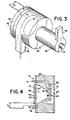
- the Fig. 4 form of ink jet head is much like the Fig. l form. Consequently, components of the Fig. 4 ink jet head are designated with the same number as corresponding components of the Fig. l ink jet head.
- the Fig. 4 form of the invention eliminates the optional purging outlet.
- ink chamber section 26 of the Fig. 4 form of ink chamber l4 is generally of frustoconical shape. However, the chamber l4 may be cylindrical or of other shapes.
- the Fig. l form of ink jet head may be manufactured by simply laminating together sheets of material which have been drilled or fabricated with the appropriate openings. Because of this relatively simply manufacturing technique, it is extremely easy to align ink drop-forming orifice 23 and the external orifice 24. It is also easy to manufacture arrays of multiple ink jet heads. In comparison, the ink jet head of Fig. 4 typically includes some cast or machined parts.
- Ink jet heads in accordance with the present invention are capable of operation at an extremely high print operating or ink drop-production rates, such as from zero to twenty kilohertz.
- an ink jet head in accordance with the invention is designed such that the natural frequency of the components of the head are greater than the maximum desired operating frequencies of the head.
- the natural frequencies of each of the components are sufficiently different from each other to prevent intercoupling of these elements. Such intercoupling could block the ink drop-production.
- the ink supply passageway 38 is designed to have a cross-sectional area that is large enough to allow the supply of ink into the ink chamber l4.
- the cross-sectional area of ink inlet passageway 38 is small enough to prevent the natural frequencies of the ink in the ink inlet passageway from significantly interfering with pressure pulses generated by the piezoelectric crystal 44 within the ink chamber l4. That is, the frequencies of ink in the ink inlet does not significantly alter the damping ratio, magnitude, or frequency of the pressure pulses in the ink chamber.
- the purging outlet 40 is about the same size as the purging inlet. However, the size of the ink inlet has a greater effect on the performance of the ink jet head because ink is supplied through this inlet during drop formation.
- the ink orifice passageway and ink chamber are sized such that the natural frequency of ink in the ink passageway 22 is at least greater than or equal to seventy-five percent of the maximum operating frequency.
- the ink jet head is typically designed such that the natural frequency of ink in the ink orifice passageway 22 is outside of the range of from ninety to one hundred and ten percent of the maximum operating frequency. This natural frequency is primarily dependent upon the geometrical dimensions of the ink orifice passageway 22 and on the overall volume of the ink chamber.
- the actuator assembly comprised of piezoelectric crystal 44 and diaphragm plate 43, should have a natural frequency of greater than two hundred and fifty percent of the maximum operating frequency of the ink jet head.
- the natural frequency of this assembly should be between one hundred kilohertz and two hundred kilohertz assuming an ink jet head operable at up to twenty kilohertz is desired.
- the axial acoustic frequency in the direction of axis 25 and dependent upon the axial distance between the diaphragm plate 43 and ink chamber wall l8, should preferably be from four hundred kilohertz to eight hundred kilohertz. This again assumes that an ink jet head operable at up to twenty kilohertz is desired. Also, the natural frequency of the ink chamber wall l8, for an ink jet head operable at up to twenty kilohertz, should preferably be greater than or equal to eight hundred and fifty kilohertz.
- the ink orifice passageway is sized such that the natural resonance frequency of ink inside the ink orifice passageway is greater than sixteen kilohertz.
- the actuator assembly typically generates a peak positive pressure within the ink chamber which is from about five pounds per square inch to about twenty pounds per square inch. Also, the actuator assembly generates a peak negative pressure within the ink chamber which is from about negative five pounds per square inch to about negative two pounds per square inch.
- a single ink chamber air-assisted drop-on-demand ink jet head capable of operating at extremely high drop repetition rates.
- the drop formation process is stabilized, with one uniform dot being produced on the printing medium per pressure pulse.
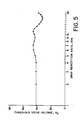
- a relatively constant peak to peak drive voltage, V D is required to generate ink drops over a wide range of drop repetition rates.
- a typical peak to peak drive voltage required by an ink jet head of the present invention is about forty volts over the full range of drop-repetition rates, through and including twenty kilohertz.
- known air assisted drop-on-demand ink jet heads typically require drive voltages which are substantially higher. Therefore, drive circuits utilized in operating ink jet heads in accordance with the present invention can be simplified, while still producing the desired results.
- FIG. 6 and 7 A method and apparatus for purging contaminants and air bubbles from an ink jet head will next be described with reference to Figs. 6 and 7.
- This method and apparatus may be used in conjunction with a wide variety of ink jet heads, in addition to the ink jet head of Fig. l.
- it is suitable for air and non-air assisted ink jet heads.
- This purging capability facilitates the initial filling of dry ink jet heads, the filling of ink jet heads which contain some ink, storage of ink jet heads, purging of bubbles and other contaminants from ink jet heads and the transportation of such heads.
- conventional ink jet heads when filled with ink and shipped at high altitudes by airline, are somewhat prone to outgassing of air bubbles into the ink within such ink jet heads.
- any bubbles ingested during storage and shipment of an ink jet head can readily be removed.
- the illustrated method and apparatus permits in situ purging of contaminants and air bubbles from ink jet heads without the need for removing the heads from an ink jet printer. This minimizes down time for such printers and makes the entire purging procedure much easier.
- the purging operation can be accomplished in only a few seconds. Also, purging typically requires only a very small fraction of the volume of ink in ink cartridges commonly used with ink jet heads.
- FIG. 7 an array of ink jet heads l0, l0a, l0b and l0c, such as the type in Fig. l, are shown.
- air under a positive pressure from an air pump 60 is delivered through a pressure regulator 62, through a closed solenoid controlled valve 64 (shown in a first position) to a line 66 and then to the air supply inlets of the respective ink jet heads.
- air from pump 60 passes through another regulator 68, through a solenoid controlled valve 70, through a line 72, and to the air pressure side of a set of conventional ink jet cartridges 74, 74a, 74b and 74c.
- Exemplary cartridges include those shown in U.S. Patent 4,55l,734 of Causley et al.
- the ink delivery side of cartridge 74 is connected through a line 76, a conventional bubble trap 78 and to the ink supply inlet 36 of ink jet head l0.
- the ink supply sides of the cartridges 74a-74c are respectively coupled by lines 76a-76c, through bubble traps 78a-78c, and to the ink supply inlets 36a-36c of ink jet heads l0a-l0c.
- the purging outlet of ink jet head l0 is coupled by a line 80 to one side of a normally closed purging valve 82.
- the other side of valve 82 is connected by a line 84 to a purging tank 86, which may be a closed vessel in which a vacuum is drawn by an optional vacuum pump 88.
- the purging outlets of the ink jet heads l0a-l0c are connected by respective lines 80A-80C to solenoid controlled valves 82a-82c. These latter valves are connected by respective lines 84a-84c to the purging tank 86.
- solenoid controlled valve 70 is shifted to a second position, shown in Fig. 7, so as to couple the air pump 60 to the line 72 and bypass the pressure regulator 68.
- This increases the pressure on ink in the ink cartridges 74-74c.
- An exemplary pressure increase is approximately four pounds-per-square-inch. This pressure increase produces a corresponding pressure increase at the respective ink supply inlets 36-36c and increases the pressure of the ink within the ink chambers of the ink jet heads.
- the solenoid controlled valves 82-82c are opened to thereby open the purging outlets of each of the ink jet heads l0-l0c.
- ink flows from the ink supply inlet of each ink jet head, through the ink chambers and purging outlets of the heads, and to the purging tank 86.
- a small amount of ink for example, approximately twenty percent of the mass flow, will pass through the orifice passageway 22 of each of the ink jet heads in addition to the ink which exits via the purging outlets.
- the resulting flow of ink through the ink chambers sweeps contaminants and bubbles from the chambers. Because the ink does not pass through a restricted orifice between the inlet and purging outlet, the velocity of ink flow through the ink chamber increases rapidly after purging is started and assists the purging process.
- the Fig. l form of ink jet head has an ink supply passageway 38 and a purging passageway 40 at opposite ends of the ink chamber from one another. These passageways are positioned such that the ink flows in a non-linear path through the ink chamber during purging. This facilitates the sweeping of contaminants and bubbles from the ink chamber. As shown in Fig. 3, by introducing the ink tangentially into the ink chamber l4, the ink follows in a cyclone-like or vortical path through the ink chamber. This tends to sweep bubbles and contaminants clinging to the ink chamber walls from the ink chamber.
- valves 82-82c are closed to shut off the purging outlets.
- Valve 70 is also shifted to its first position so as to again deliver regulated air to the ink cartridges.
- solenoid valve 64 may be shifted to its second position to vent air from line 66. This prevents the delivery of air to the air chambers of ink jet heads l0-l0c during the purging operation.
- the vacuum pump 88 is employed to draw a vacuum, for example a negative four pounds-per-square-inch vacuum, in vessel 86.
- the valves 82-82c are opened so that this negative pressure is applied to the purging outlets of the ink jet heads l0-l0c.
- valve 64 may be moved to its vent position and valve 70 is typically left in the position shown in Fig. 7 so that a normal positive pressure exists at the ink inlet.
- ink not only flows from the supply inlet of each ink jet head to the purging outlet, but the velocity of ink flow is increased. With this approach, very little ink typically flows through the ink orifice passageways. Consequently, the remote chance of forcing contaminants and bubbles into these passageways and clogging the ink jet heads during the purging operation is reduced.
- an ink jet head which is wetted with fluid is drained through the purging outlet.
- a dry ink jet head may be initially wetted and then purged in this manner.
- an ink jet head which is wetted during normal operation may be drained and purged accordingly.
- drive signals such as sinusoidal signals, at a desired frequency are obtained from a conventional signal source 90. These signals are delivered through analog switches 92 and through ink jet amplifiers to the piezoelectric crystal of each ink jet head of an ink jet head array.
- a switch 96 is closed to trigger a monostable multivibrator 98.
- the multivibrator 98 produces an output to ink and air valve solenoid drivers l00 and to the analog switches 92. While the monostable multivibrator is producing such an output signal, drivers l00 control the valves 64, 70 and 82-82c as previously explained to accomplish the purging operation.
- analog switches 92 are controlled during this time to block the application of drive signals to the piezoelectric crystals of the ink jet heads from source 90.
- the valves return to their normal position so that normal operation of the ink jet heads resumes.
- a purge signal source l02 may be provided. This source is coupled by the analog switches 92 to the ink jet amplifiers 94 during the purging operation.
- Purge signal source l02 comprises a ramp generator circuit l04 for applying a ramp voltage to a voltage controlled oscillator l06. In response to the ramp voltage output from the ramp generator, the voltage controlled oscillator produces a sinusoidal output which is varied from approximately five kilohertz to about one hundred kilohertz. This sweeping frequency signal, when applied to the piezoelectric crystals of the ink jet heads, causes any bubbles in the ink chamber to oscillate. Oscillation is enhanced when the applied frequency is at the natural resonance frequency of the bubbles.
- the bubbles oscillate, they tend to break up and dislodge from the walls of the ink chamber. This makes the bubbles easier to sweep from the ink chamber during the purging operation.
- the frequency of the applied purging signal is continuously varied over a range, as compared to applying a few isolated purging signal frequencies. Because of this, virtually any bubble of significant size within the ink chamber will be subjected to an applied signal at the natural resonance frequency of the bubble. Consequently, removal of the bubbles is enhanced.
- successful purging typically is accomplished by the previously described purging cycles without subjecting ink jet heads to a variable frequency purging signal. However, particularly when initially filling a dry ink jet head, in some cases the application of a variable frequency purging signal has removed bubbles that were not removed in the absence of such a signal.
Landscapes
- Particle Formation And Scattering Control In Inkjet Printers (AREA)
- Ink Jet (AREA)
Applications Claiming Priority (2)
| Application Number | Priority Date | Filing Date | Title |
|---|---|---|---|
| US884845 | 1986-07-11 | ||
| US06/884,845 US4728969A (en) | 1986-07-11 | 1986-07-11 | Air assisted ink jet head with single compartment ink chamber |
Publications (2)
| Publication Number | Publication Date |
|---|---|
| EP0252676A2 true EP0252676A2 (fr) | 1988-01-13 |
| EP0252676A3 EP0252676A3 (fr) | 1988-12-28 |
Family
ID=25385548
Family Applications (1)
| Application Number | Title | Priority Date | Filing Date |
|---|---|---|---|
| EP87305819A Withdrawn EP0252676A3 (fr) | 1986-07-11 | 1987-07-01 | Tête d'impression à projection d'encre à aspiration d'air avec une chambre à encre à compartiment unique |
Country Status (3)
| Country | Link |
|---|---|
| US (1) | US4728969A (fr) |
| EP (1) | EP0252676A3 (fr) |
| JP (1) | JPS6328658A (fr) |
Cited By (3)
| Publication number | Priority date | Publication date | Assignee | Title |
|---|---|---|---|---|
| WO1997031779A1 (fr) * | 1996-02-28 | 1997-09-04 | Dataproducts Corporation | Dispositif a jet d'encre fonctionnant a l'aide d'un gaz et procede correspondant |
| EP1289764A4 (fr) * | 2000-05-24 | 2004-11-17 | Silverbrook Res Pty Ltd | Dispositif d'alimentation en air pour imprimante |
| US7467859B2 (en) | 2000-05-23 | 2008-12-23 | Silverbrook Research Pty Ltd | Pagewidth printhead assembly with ink distribution arrangement |
Families Citing this family (46)
| Publication number | Priority date | Publication date | Assignee | Title |
|---|---|---|---|---|
| US4875619A (en) * | 1988-09-01 | 1989-10-24 | Anderson Jeffrey J | Brazing of ink jet print head components using thin layers of braze material |
| US4883219A (en) * | 1988-09-01 | 1989-11-28 | Anderson Jeffrey J | Manufacture of ink jet print heads by diffusion bonding and brazing |
| USD321899S (en) | 1989-03-27 | 1991-11-26 | Dataproducts Corporation | Reinker cartridge |
| US5170177A (en) * | 1989-12-15 | 1992-12-08 | Tektronix, Inc. | Method of operating an ink jet to achieve high print quality and high print rate |
| DE69214418T2 (de) * | 1991-12-30 | 1997-03-06 | Xerox Corp | Akustischer Tintendruckkopf mit einem gelöcherten Element und einem Tintenfluss |
| GB9221833D0 (en) * | 1992-10-16 | 1992-12-02 | Willett Int Ltd | Method for assembling devices |
| US5461401A (en) * | 1992-11-05 | 1995-10-24 | Videojet Systems International, Inc. | Frequency optimized ink jet printer |
| US6065825A (en) * | 1997-11-13 | 2000-05-23 | Eastman Kodak Company | Printer having mechanically-assisted ink droplet separation and method of using same |
| US6136442A (en) * | 1998-09-30 | 2000-10-24 | Xerox Corporation | Multi-layer organic overcoat for particulate transport electrode grid |
| US6467862B1 (en) | 1998-09-30 | 2002-10-22 | Xerox Corporation | Cartridge for use in a ballistic aerosol marking apparatus |
| US6511149B1 (en) | 1998-09-30 | 2003-01-28 | Xerox Corporation | Ballistic aerosol marking apparatus for marking a substrate |
| US6454384B1 (en) | 1998-09-30 | 2002-09-24 | Xerox Corporation | Method for marking with a liquid material using a ballistic aerosol marking apparatus |
| US6416156B1 (en) | 1998-09-30 | 2002-07-09 | Xerox Corporation | Kinetic fusing of a marking material |
| US6116718A (en) * | 1998-09-30 | 2000-09-12 | Xerox Corporation | Print head for use in a ballistic aerosol marking apparatus |
| US6290342B1 (en) | 1998-09-30 | 2001-09-18 | Xerox Corporation | Particulate marking material transport apparatus utilizing traveling electrostatic waves |
| US6340216B1 (en) | 1998-09-30 | 2002-01-22 | Xerox Corporation | Ballistic aerosol marking apparatus for treating a substrate |
| US6523928B2 (en) | 1998-09-30 | 2003-02-25 | Xerox Corporation | Method of treating a substrate employing a ballistic aerosol marking apparatus |
| US6751865B1 (en) | 1998-09-30 | 2004-06-22 | Xerox Corporation | Method of making a print head for use in a ballistic aerosol marking apparatus |
| US6265050B1 (en) | 1998-09-30 | 2001-07-24 | Xerox Corporation | Organic overcoat for electrode grid |
| US6291088B1 (en) | 1998-09-30 | 2001-09-18 | Xerox Corporation | Inorganic overcoat for particulate transport electrode grid |
| US6416157B1 (en) | 1998-09-30 | 2002-07-09 | Xerox Corporation | Method of marking a substrate employing a ballistic aerosol marking apparatus |
| EP1023997B1 (fr) * | 1999-01-29 | 2007-03-21 | Seiko Epson Corporation | Dispositif actionneur et appareil d'enregistrement à jet d'encre |
| US6293659B1 (en) | 1999-09-30 | 2001-09-25 | Xerox Corporation | Particulate source, circulation, and valving system for ballistic aerosol marking |
| US6328436B1 (en) | 1999-09-30 | 2001-12-11 | Xerox Corporation | Electro-static particulate source, circulation, and valving system for ballistic aerosol marking |
| CN100352653C (zh) * | 2000-05-24 | 2007-12-05 | 西尔弗布鲁克研究有限公司 | 带有空气供应装置的打印头 |
| SE0102088D0 (sv) * | 2001-06-13 | 2001-06-13 | Thomas Laurell | Device for compound dispensing |
| US6588889B2 (en) | 2001-07-16 | 2003-07-08 | Eastman Kodak Company | Continuous ink-jet printing apparatus with pre-conditioned air flow |
| TW558611B (en) | 2001-07-18 | 2003-10-21 | Matsushita Electric Industrial Co Ltd | Small pump, cooling system and portable equipment |
| US6863384B2 (en) | 2002-02-01 | 2005-03-08 | Eastman Kodak Company | Continuous ink jet method and apparatus |
| US7052117B2 (en) * | 2002-07-03 | 2006-05-30 | Dimatix, Inc. | Printhead having a thin pre-fired piezoelectric layer |
| US6969160B2 (en) * | 2003-07-28 | 2005-11-29 | Xerox Corporation | Ballistic aerosol marking apparatus |
| US20050157112A1 (en) | 2004-01-21 | 2005-07-21 | Silverbrook Research Pty Ltd | Inkjet printer cradle with shaped recess for receiving a printer cartridge |
| US7448734B2 (en) * | 2004-01-21 | 2008-11-11 | Silverbrook Research Pty Ltd | Inkjet printer cartridge with pagewidth printhead |
| US7303255B2 (en) * | 2004-01-21 | 2007-12-04 | Silverbrook Research Pty Ltd | Inkjet printer cartridge with a compressed air port |
| US7121655B2 (en) * | 2004-01-21 | 2006-10-17 | Silverbrook Research Pty Ltd | Inkjet printer cartridge refill dispenser |
| US7097291B2 (en) * | 2004-01-21 | 2006-08-29 | Silverbrook Research Pty Ltd | Inkjet printer cartridge with ink refill port having multiple ink couplings |
| US7281778B2 (en) * | 2004-03-15 | 2007-10-16 | Fujifilm Dimatix, Inc. | High frequency droplet ejection device and method |
| US8491076B2 (en) | 2004-03-15 | 2013-07-23 | Fujifilm Dimatix, Inc. | Fluid droplet ejection devices and methods |
| NL1026486C2 (nl) * | 2004-06-23 | 2005-12-28 | Oce Tech Bv | Inkjetsysteem, werkwijze om dit systeem te maken en toepassing van dit systeem. |
| EP1836056B1 (fr) | 2004-12-30 | 2018-11-07 | Fujifilm Dimatix, Inc. | Impression a jet d'encre |
| JP4915260B2 (ja) * | 2006-03-31 | 2012-04-11 | ブラザー工業株式会社 | 液体流路構造及び液滴噴射装置 |
| US7988247B2 (en) * | 2007-01-11 | 2011-08-02 | Fujifilm Dimatix, Inc. | Ejection of drops having variable drop size from an ink jet printer |
| US7914109B2 (en) * | 2007-11-26 | 2011-03-29 | Eastman Kodak Company | Liquid drop dispenser with movable deflector |
| US7914121B2 (en) * | 2008-02-01 | 2011-03-29 | Eastman Kodak Company | Liquid drop dispenser with movable deflector |
| US8714716B2 (en) | 2010-08-25 | 2014-05-06 | Illinois Tool Works Inc. | Pulsed air-actuated micro-droplet on demand ink jet |
| US9089863B2 (en) | 2012-04-17 | 2015-07-28 | Illinois Tool Works Inc. | Method for cleaning a nozzle of a material deposition system |
Family Cites Families (12)
| Publication number | Priority date | Publication date | Assignee | Title |
|---|---|---|---|---|
| SE349676B (fr) * | 1971-01-11 | 1972-10-02 | N Stemme | |
| GB1450340A (en) * | 1973-08-16 | 1976-09-22 | Matsushita Electric Ind Co Ld | Arrangements for applying liquid droplets to a surface |
| US4106032A (en) * | 1974-09-26 | 1978-08-08 | Matsushita Electric Industrial Co., Limited | Apparatus for applying liquid droplets to a surface by using a high speed laminar air flow to accelerate the same |
| DE2927488A1 (de) * | 1979-07-07 | 1981-01-22 | Philips Patentverwaltung | Tintenstrahldrucker |
| US4380018A (en) * | 1980-06-20 | 1983-04-12 | Sanyo Denki Kabushiki Kaisha | Ink droplet projecting device and an ink jet printer |
| JPS57174269A (en) * | 1981-04-20 | 1982-10-26 | Ricoh Co Ltd | Ink chamber structure for ink jetting head |
| JPS58220758A (ja) * | 1982-06-16 | 1983-12-22 | Matsushita Electric Ind Co Ltd | インクジエツト記録装置 |
| US4518974A (en) * | 1982-09-21 | 1985-05-21 | Ricoh Company, Ltd. | Ink jet air removal system |
| JPS59192576A (ja) * | 1983-04-18 | 1984-10-31 | Matsushita Electric Ind Co Ltd | インクジエツト記録装置 |
| US4549188A (en) * | 1984-01-09 | 1985-10-22 | The Mead Corporation | Orifice plate for ink jet printer |
| US4613875A (en) * | 1985-04-08 | 1986-09-23 | Tektronix, Inc. | Air assisted ink jet head with projecting internal ink drop-forming orifice outlet |
| JPH106871A (ja) * | 1996-06-21 | 1998-01-13 | Suzuki Motor Corp | ジャッキハンドルの格納構造 |
-
1986
- 1986-07-11 US US06/884,845 patent/US4728969A/en not_active Expired - Fee Related
-
1987
- 1987-07-01 EP EP87305819A patent/EP0252676A3/fr not_active Withdrawn
- 1987-07-10 JP JP62172719A patent/JPS6328658A/ja active Pending
Cited By (6)
| Publication number | Priority date | Publication date | Assignee | Title |
|---|---|---|---|---|
| WO1997031779A1 (fr) * | 1996-02-28 | 1997-09-04 | Dataproducts Corporation | Dispositif a jet d'encre fonctionnant a l'aide d'un gaz et procede correspondant |
| US7467859B2 (en) | 2000-05-23 | 2008-12-23 | Silverbrook Research Pty Ltd | Pagewidth printhead assembly with ink distribution arrangement |
| US7931358B2 (en) | 2000-05-23 | 2011-04-26 | Silverbrook Research Pty Ltd | Pagewidth printhead assembly with top-fed ink ducts |
| US8075112B2 (en) | 2000-05-23 | 2011-12-13 | Silverbrook Research Pty Ltd | Printhead assembly with air cleaning arrangement |
| EP1289764A4 (fr) * | 2000-05-24 | 2004-11-17 | Silverbrook Res Pty Ltd | Dispositif d'alimentation en air pour imprimante |
| US7357475B2 (en) | 2000-05-24 | 2008-04-15 | Silverbrook Research Pty Ltd | Filtered air supply for nozzle guard |
Also Published As
| Publication number | Publication date |
|---|---|
| US4728969A (en) | 1988-03-01 |
| EP0252676A3 (fr) | 1988-12-28 |
| JPS6328658A (ja) | 1988-02-06 |
Similar Documents
| Publication | Publication Date | Title |
|---|---|---|
| US4728969A (en) | Air assisted ink jet head with single compartment ink chamber | |
| US4727378A (en) | Method and apparatus for purging an ink jet head | |
| US4613875A (en) | Air assisted ink jet head with projecting internal ink drop-forming orifice outlet | |
| EP0467656B1 (fr) | Méthode de commande pour tête d'impression à jet d'encre fonctionnant à la demande | |
| US4475113A (en) | Drop-on-demand method and apparatus using converging nozzles and high viscosity fluids | |
| US4491851A (en) | Method and circuit for driving an ink jet printer | |
| US5170177A (en) | Method of operating an ink jet to achieve high print quality and high print rate | |
| US6250752B1 (en) | Ink supply device and ink-jet recording head with filter and shaped flow passage | |
| US4751530A (en) | Acoustic lens arrays for ink printing | |
| EP0960025B1 (fr) | Dispositif a jet d'encre fonctionnant a l'aide d'un gaz et procede correspondant | |
| US4353078A (en) | Ink jet print head having dynamic impedance adjustment | |
| EP0575204A2 (fr) | Méthode de commande d'un jet d'encre pour réaliser une haute qualité d'impression et un haut débit d'impression | |
| WO2008045235A1 (fr) | Émetteur de gouttes en continu avec diaphonie à stimulation réduite | |
| US6394589B1 (en) | Ink jet printhead with reduced crosstalk | |
| US4703330A (en) | Color ink jet drop generator using a solid acoustic cavity | |
| US4641155A (en) | Printing head for ink jet printer | |
| EP0054114B1 (fr) | Dispositif pour former une gouttelette liquide | |
| EP0067948B1 (fr) | Méthode et appareil pour produire des gouttes liquides sur demande | |
| JP3324652B2 (ja) | インクジェット記録ヘッド | |
| JPS62105636A (ja) | インクジエツトプリンタ用液滴発生器 | |
| JPH02209245A (ja) | 印刷装置 | |
| JPH08207276A (ja) | インクジェットプリントヘッド | |
| JPS6422556A (en) | Drop generator of on-demand type ink jet head | |
| JPS58167168A (ja) | インクジエツト記録装置の駆動方法 | |
| JPS60145857A (ja) | 液滴吐出装置 |
Legal Events
| Date | Code | Title | Description |
|---|---|---|---|
| PUAI | Public reference made under article 153(3) epc to a published international application that has entered the european phase |
Free format text: ORIGINAL CODE: 0009012 |
|
| AK | Designated contracting states |
Kind code of ref document: A2 Designated state(s): DE FR GB NL |
|
| PUAL | Search report despatched |
Free format text: ORIGINAL CODE: 0009013 |
|
| AK | Designated contracting states |
Kind code of ref document: A3 Designated state(s): DE FR GB NL |
|
| 17P | Request for examination filed |
Effective date: 19890603 |
|
| 17Q | First examination report despatched |
Effective date: 19901011 |
|
| STAA | Information on the status of an ep patent application or granted ep patent |
Free format text: STATUS: THE APPLICATION IS DEEMED TO BE WITHDRAWN |
|
| 18D | Application deemed to be withdrawn |
Effective date: 19930113 |
|
| RIN1 | Information on inventor provided before grant (corrected) |
Inventor name: ADAMS, RONALD L. Inventor name: OSWALD, JAMES C. Inventor name: ROY, JOY Inventor name: LE, HUE PHUOC Inventor name: ANDERSON, JEFFREY J. |