EP0252687A2 - Regnergerät mit Taumelbewegung zum Beaufschlagen einer vorgegebenen Fläche - Google Patents
Regnergerät mit Taumelbewegung zum Beaufschlagen einer vorgegebenen Fläche Download PDFInfo
- Publication number
- EP0252687A2 EP0252687A2 EP87305871A EP87305871A EP0252687A2 EP 0252687 A2 EP0252687 A2 EP 0252687A2 EP 87305871 A EP87305871 A EP 87305871A EP 87305871 A EP87305871 A EP 87305871A EP 0252687 A2 EP0252687 A2 EP 0252687A2
- Authority
- EP
- European Patent Office
- Prior art keywords
- support arm
- distributor head
- further characterized
- water
- base
- Prior art date
- Legal status (The legal status is an assumption and is not a legal conclusion. Google has not performed a legal analysis and makes no representation as to the accuracy of the status listed.)
- Withdrawn
Links
Images

Classifications
-
- B—PERFORMING OPERATIONS; TRANSPORTING
- B05—SPRAYING OR ATOMISING IN GENERAL; APPLYING FLUENT MATERIALS TO SURFACES, IN GENERAL
- B05B—SPRAYING APPARATUS; ATOMISING APPARATUS; NOZZLES
- B05B3/00—Spraying or sprinkling apparatus with moving outlet elements or moving deflecting elements
- B05B3/02—Spraying or sprinkling apparatus with moving outlet elements or moving deflecting elements with rotating elements
- B05B3/04—Spraying or sprinkling apparatus with moving outlet elements or moving deflecting elements with rotating elements driven by the liquid or other fluent material discharged, e.g. the liquid actuating a motor before passing to the outlet
- B05B3/06—Spraying or sprinkling apparatus with moving outlet elements or moving deflecting elements with rotating elements driven by the liquid or other fluent material discharged, e.g. the liquid actuating a motor before passing to the outlet by jet reaction
- B05B3/066—Spraying or sprinkling apparatus with moving outlet elements or moving deflecting elements with rotating elements driven by the liquid or other fluent material discharged, e.g. the liquid actuating a motor before passing to the outlet by jet reaction the movement of the outlet elements being a combination of two movements, one being rotational
-
- B—PERFORMING OPERATIONS; TRANSPORTING
- B05—SPRAYING OR ATOMISING IN GENERAL; APPLYING FLUENT MATERIALS TO SURFACES, IN GENERAL
- B05B—SPRAYING APPARATUS; ATOMISING APPARATUS; NOZZLES
- B05B3/00—Spraying or sprinkling apparatus with moving outlet elements or moving deflecting elements
- B05B3/008—Spraying or sprinkling apparatus with moving outlet elements or moving deflecting elements comprising a wobbling or nutating element, e.g. rotating about an axis describing a cone during spraying
-
- B—PERFORMING OPERATIONS; TRANSPORTING
- B05—SPRAYING OR ATOMISING IN GENERAL; APPLYING FLUENT MATERIALS TO SURFACES, IN GENERAL
- B05B—SPRAYING APPARATUS; ATOMISING APPARATUS; NOZZLES
- B05B3/00—Spraying or sprinkling apparatus with moving outlet elements or moving deflecting elements
- B05B3/02—Spraying or sprinkling apparatus with moving outlet elements or moving deflecting elements with rotating elements
- B05B3/04—Spraying or sprinkling apparatus with moving outlet elements or moving deflecting elements with rotating elements driven by the liquid or other fluent material discharged, e.g. the liquid actuating a motor before passing to the outlet
- B05B3/0417—Spraying or sprinkling apparatus with moving outlet elements or moving deflecting elements with rotating elements driven by the liquid or other fluent material discharged, e.g. the liquid actuating a motor before passing to the outlet comprising a liquid driven rotor, e.g. a turbine
- B05B3/0429—Spraying or sprinkling apparatus with moving outlet elements or moving deflecting elements with rotating elements driven by the liquid or other fluent material discharged, e.g. the liquid actuating a motor before passing to the outlet comprising a liquid driven rotor, e.g. a turbine the rotating outlet elements being directly attached to the rotor or being an integral part thereof
-
- B—PERFORMING OPERATIONS; TRANSPORTING
- B05—SPRAYING OR ATOMISING IN GENERAL; APPLYING FLUENT MATERIALS TO SURFACES, IN GENERAL
- B05B—SPRAYING APPARATUS; ATOMISING APPARATUS; NOZZLES
- B05B3/00—Spraying or sprinkling apparatus with moving outlet elements or moving deflecting elements
- B05B3/02—Spraying or sprinkling apparatus with moving outlet elements or moving deflecting elements with rotating elements
- B05B3/04—Spraying or sprinkling apparatus with moving outlet elements or moving deflecting elements with rotating elements driven by the liquid or other fluent material discharged, e.g. the liquid actuating a motor before passing to the outlet
- B05B3/0417—Spraying or sprinkling apparatus with moving outlet elements or moving deflecting elements with rotating elements driven by the liquid or other fluent material discharged, e.g. the liquid actuating a motor before passing to the outlet comprising a liquid driven rotor, e.g. a turbine
- B05B3/0444—Spraying or sprinkling apparatus with moving outlet elements or moving deflecting elements with rotating elements driven by the liquid or other fluent material discharged, e.g. the liquid actuating a motor before passing to the outlet comprising a liquid driven rotor, e.g. a turbine the movement of the outlet elements being a combination of two movements, one being rotational
-
- B—PERFORMING OPERATIONS; TRANSPORTING
- B05—SPRAYING OR ATOMISING IN GENERAL; APPLYING FLUENT MATERIALS TO SURFACES, IN GENERAL
- B05B—SPRAYING APPARATUS; ATOMISING APPARATUS; NOZZLES
- B05B3/00—Spraying or sprinkling apparatus with moving outlet elements or moving deflecting elements
- B05B3/14—Spraying or sprinkling apparatus with moving outlet elements or moving deflecting elements with oscillating elements; with intermittent operation
- B05B3/16—Spraying or sprinkling apparatus with moving outlet elements or moving deflecting elements with oscillating elements; with intermittent operation driven or controlled by the liquid or other fluent material discharged, e.g. the liquid actuating a motor before passing to the outlet
Definitions
- This invention relates to sprinklers, especially to sprinklers for supplying water to lawns and other vegetation. More particularly, the invention relates to sprinklers having a wobbling water distributor head, providing a means for controlling the dimensions of the area to which water is supplied by the sprinkler.
- U.S. Patent No. 4,487,368 describes a sprinkler device incorporating a novel wobbling water distributor head mounted at the end of a tubular water-supplying support arm.
- the wobbling motion of the distributor head causes the support arm, (and, of course, the water stream) to describe a circular path, so that the sprinkler supplies water to a circular surrounding area.
- the radius of this circular area can be varied somewhat by controlling the pressure of the water supplied to the sprinkler, the device does not provide for sprinkling an area of any other shape.
- the present invention constitutes an improvement over the sprinkler of aforementioned U.S. Patent No. 4,487,368 in that the area to which water is supplied can be adjusted and varied by means of a simple adjustment to the sprinkler without adjusting the pressure of the water supplied.
- the invention provides a simple means for providing water to noncircular areas, e.g., square or rectangular areas.
- the sprinkler of U.S. Patent No. 4,487,368 is a device comprising a wobbling water distributor head having a base end with a hole extending therethrough, the base being loosely mounted on the distal portion of an angularly disposed tubular water-transporting arm between spaced upper and lower shoulders, the arm being horizontally rotatable about a locus at its proximal end.
- the improvement contributed by the present invention comprises means for controllably varying the distance between the shoulders, whereby the dimensions of the area watered by the device are also controllably varied.
- the invention may be described as a sprinkling device of the type comprising a wobbling water distributor head that has a base with a hole extending therethrough, said base being loosely mounted on the distal portion of a tubular water-transporting support arm between spaced shoulders, wherein the device comprises means for continually and controllably varying the distance between said shoulders while said device is carrying out its sprinkling function, whereby the dimensions of the area watered by said device can also be continually and controllably varied.
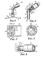
- sprinkler base 10 comprises sled 11 connected to housing 12.
- housing 12 At the upper side of housing 12 is an internally threaded opening, into which is threaded vertically extending bearing 13, at the upper end of which is located suitably contoured (e.g., square) cam 15.
- Rotatably positioned within bearing 13 is vertical water transport 16, having head 16a, which seats against the lower end of bearing 13.
- the upper end of water transport 16 is threaded, and angularly disposed tubular water-transporting support arm 17 is attached thereto.
- support arm 17 is optionally provided with flow straightener 36 to minimize turbulence of the water stream passing therethrough.
- support arm 17 is provided with nozzle 20, having at its outer end a circular ridge, the lower portion of which functions as upper shoulder 21, in a manner to be described.
- Slidably surrounding support arm 17 is spacer sleeve 23, the distal edge of which functions as lower shoulder surface 24.
- Generally cup-shaped distributor head 30 has a base 31, in the central portion of which is hole 32. Base 31 of distributor head 30 is mounted between upper shoulder 21 and lower shoulder 24, hole 32 loosely surrounding nozzle 20.
- Axially extending rib 19 in the upper surface of nozzle 20 fits loosely into notch 33 extending from the portion of base 31 that surrounds hole 32, rib 19 and notch 33 forming a cooperative means that prevents distributor head 30 from rotating but permits it to wobble as one portion of the inner surface of base 31 contacts upper shoulder 21; the diametrically opposite outer surface of base 31 contacts the lower shoulder 24.
- distributor head 30 would be free to precess. While not objectionable per se, such an arrangement would require the water jet to contact all the vanes in order to effect a wobbling motion. With driver vanes 34 always at the top and extending past 90° in the direction of wobble, operation is assured even when the water jet does not contact distributing vanes 35 at all.
- the discharge end of distributor head 30 is provided with internal driver vanes 34 and distributing vanes 35, extending at a slight angle (e.g., 15°) to the longitudinal axis of head 20.
- Driver vanes 34 located at the upper portion of head 30, are longer than distributor vanes 35, ensuring that a stream of water will strike them when the sprinkler is initially turned on.
- As the water strikes driver vanes 34 their angled orientation causes head 30 to seek to rotate. Because notch 33 is loosely seated in rib 19, rotation of base 31 is prevented; the discharge end of distributor head 30, however, is not restricted in this manner, and a wobbling motion then takes place.
- the distal edge of support arm 17 is provided with axially extending tongue 22, and the lower edge of spacer sleeve 23 is provided with a series of axially extending grooves, viz., camming groove 25 and circle-generating grooves 26 and 27, the desired one of which is fitted to tongue 22 during operation of the sprinkler by appropriately rotating sleeve 23.
- Groove 26 is shorter than groove 27, so that when tongue 22 is fitted into groove 26 the distance between shoulders 21 and 24 is less than when tongue 22 is fitted into groove 27.
- fitting tongue 22 into groove 26 will cause a stream of water to project to a greater radial distance than fitting it into groove 27, the greatest distance being achieved when the stream makes minimal contact with driver vanes 34 and no contact with distributor vanes 35.
- Grooves 26 and 27 may thus be employed to control the size of the circular area sprinkled. It will, of course, be apparent that more than two grooves could be provided, permitting even further control of the size of the area sprinkled.
- cam follower 28 which is incorporated into sleeve 23, is then so positioned that it contacts cam 15.
- support arm 17 rotates about vertical water transport 16 and cam follower 28 follows cam 15, sleeve 23 is moved axially in and out, varying with the peripheral contour of cam 15.
- Cam 15 is shown as a square, but it will be readily appreciated that it could be rectangular, in the shape of other polygons, elliptical, curvilinear, etc. depending on the contours of the area to be sprinkled.
- sharp angles on cam 15 should be avoided, rounding off all corners.
- FIGs. 6-11 depict other embodiments of the invention, employing the principles just discussed.
- the device of FIGs. 5-8 is essentially the same as that of FIGs. 9 and 10, the latter differing only in that water supply 55 is provided at a location that is slightly offset, which facilitates the horizontal rotation of the support arm about its proximal end. Dimensions of the parts in these two embodiments differ somewhat but have no significant effect on performance.
- angled support arm 54 is mounted at the top of vertical water transport 16.
- Support arm 54 is surrounded by spanner 41, comprising spacer 42, at the opposite ends of which are lower ring 43 and upper ring 44; integral with ring 44 is spacer sleeve 45, from the lower end of which tang 46 extends.
- Cam follower 57 is also integral with spacer 42, being adapted to contact cam 15 when spanner 42 is appropriately rotated about support arm 54.
- nozzle 48 Positioned in the interior of support arm 54, so as to be in line with the direction of water flow, is nozzle 48, at the outer end of which is a ridge having conically tapered lower surface serving as upper shoulder.
- the upper edge of ring 44 is also conically tapered, functioning as lower shoulder 47.
- distributor head 60 includes base 67, having outwardly conically tapered portion 68 and inwardly conically tapered portion 65, the radially inner portion defining central hole 62.
- Distributor head 60 is so mounted that hole 62 surrounds nozzle 48, with base portions 65 and 68 positioned between upper shoulder 49 and lower shoulder 47.
- the contacting portions of base 67 and the shoulders (65 and 49, 68 and 47) are desirably identically conically tapered and provided with equal radii or circumferences, thereby minimizing frictional contact or relative movement, enhancing the wobbling tendency of distributor head 60 and increasing the efficiency of operation.
- Driver vanes 64 located at the discharge end of distributor head 60, impart a wobbling motion in essentially the same manner as that described with respect to the device of FIGs. 1-5, distributor vanes 64a functioning in a manner analogous to that of distributor vanes 35.
- Notch 33 located along the perimeter of hole 62, combines with rib 19 to prevent head 60 from rotating on support arm 54.
- camming groove 51 in which tang 46 is seated when cam follower 57 contacts cam 15, is V-shaped to facilitate inward and outward motion of sleeve 45 when a noncircular pattern is to be sprinkled, and promote smoothness of operation.
- spanner 41 When tang 46 is seated in camming groove 51, spanner 41 is caused to rotate a few degrees by the interaction between cam 15 and cam follower 57, forcing a camming action between the slope of camming groove 51 and tang 46, thus advancing spanner 41 outward axially and closing the space between upper ring 44 and upper shoulder 49, thereby increasing the distance a stream of water is thrown from nozzle 48.
- cam follower 57 continues to follow cam 15, the axial distance between upper ring 44 and upper shoulder 49 increases, thereby decreasing the distance the stream of water is thrown.
- the contour of the area sprinkled is geometrically similar to the shape of cam 15.
Landscapes
- Nozzles (AREA)
Applications Claiming Priority (2)
| Application Number | Priority Date | Filing Date | Title |
|---|---|---|---|
| US06/882,270 US4773594A (en) | 1986-07-07 | 1986-07-07 | Controlled pattern wobbling sprinkler |
| US882270 | 1986-07-07 |
Publications (2)
| Publication Number | Publication Date |
|---|---|
| EP0252687A2 true EP0252687A2 (de) | 1988-01-13 |
| EP0252687A3 EP0252687A3 (de) | 1989-04-26 |
Family
ID=25380242
Family Applications (1)
| Application Number | Title | Priority Date | Filing Date |
|---|---|---|---|
| EP87305871A Withdrawn EP0252687A3 (de) | 1986-07-07 | 1987-07-02 | Regnergerät mit Taumelbewegung zum Beaufschlagen einer vorgegebenen Fläche |
Country Status (4)
| Country | Link |
|---|---|
| US (1) | US4773594A (de) |
| EP (1) | EP0252687A3 (de) |
| JP (1) | JPS6323761A (de) |
| IL (1) | IL83051A0 (de) |
Families Citing this family (15)
| Publication number | Priority date | Publication date | Assignee | Title |
|---|---|---|---|---|
| US5333787A (en) * | 1992-02-05 | 1994-08-02 | Smith Leary W | Nozzle with self controlled oscillation |
| US5381960A (en) * | 1993-08-23 | 1995-01-17 | Senninger Irrigation, Inc. | Wobbling irrigation sprinkler head including a magnet for initial tilt |
| US5950927A (en) * | 1997-10-20 | 1999-09-14 | Senninger Irrigation, Inc. | Wobbling sprinkler head |
| US6176440B1 (en) | 1997-10-20 | 2001-01-23 | Senninger Irrigation, Inc. | Wobbling sprinkler head |
| US6530532B1 (en) | 2000-02-05 | 2003-03-11 | Senninger Irrigation, Inc. | Kick-starter for sprinkler heads |
| US7070122B2 (en) | 2003-08-04 | 2006-07-04 | Senninger Irrigation Inc. | Wobbling sprinkler head |
| US6932279B2 (en) | 2003-10-27 | 2005-08-23 | Senninger Irrigation Inc. | Wobbling sprinkler head |
| US7278591B2 (en) * | 2004-08-13 | 2007-10-09 | Clearman Joseph H | Spray apparatus |
| EP1799355A1 (de) * | 2004-08-13 | 2007-06-27 | Joseph H. Clearman | Sprühvorrichtung und abgaberohre dafür |
| US8991724B2 (en) | 2012-06-06 | 2015-03-31 | Nelson Irrigation Corporation | Wobbling sprinkler with viscous brake |
| US11213836B2 (en) | 2018-11-30 | 2022-01-04 | Don D. Duffin | Nutating sprinkler head |
| US11865564B2 (en) | 2020-01-17 | 2024-01-09 | Senninger Irrigation, Inc. | Serviceable sprinkler with nutating distribution plate and wear sleeve |
| USD929535S1 (en) | 2020-03-13 | 2021-08-31 | Senninger Irrigation, Inc. | Sprinkler |
| US12048941B2 (en) | 2020-06-12 | 2024-07-30 | Senninger Irrigation, Inc. | Serviceable sprinkler with nutating distribution plate and asymmetrical water channels |
| US12582998B2 (en) | 2023-01-13 | 2026-03-24 | Hunter Agriculture Incorporated | Serviceable sprinkler with nutating distribution plate |
Family Cites Families (11)
| Publication number | Priority date | Publication date | Assignee | Title |
|---|---|---|---|---|
| US1796942A (en) * | 1928-05-31 | 1931-03-17 | Jr Francis M Pottenger | Sprinkler |
| DE699339C (de) * | 1938-02-25 | 1940-11-27 | Heinrich Perrot | Schwenkregner |
| AT158716B (de) * | 1938-05-14 | 1940-05-10 | Paul Stimmel | Sprengvorrichtung. |
| FR903592A (fr) * | 1943-05-03 | 1945-10-09 | Kugler Fonderie & Robinetterie | Jet d'arrosage mobile |
| US2670237A (en) * | 1950-02-20 | 1954-02-23 | Laux Karl | Sprinkling apparatus |
| US2620231A (en) * | 1950-03-10 | 1952-12-02 | Douglas H King | Lawn sprinkler |
| AT172230B (de) * | 1950-09-21 | 1952-08-25 | Alfred Wais | Selbsttätiger Schwenkregner, insbesondere für Quadrat- und Rechteckberegnung |
| US2848276A (en) * | 1956-11-19 | 1958-08-19 | Jack F Clearman | Liquid distributor |
| US3357643A (en) * | 1965-07-06 | 1967-12-12 | Rain Jet Corp | Sprinkler and fountain devices |
| IL28397A (en) * | 1967-07-26 | 1970-09-17 | Rosenberg P | Rotary sprinklers |
| US4487368A (en) * | 1982-10-29 | 1984-12-11 | Clearman Jack F | Vane-driven wobbling sprinkler device |
-
1986
- 1986-07-07 US US06/882,270 patent/US4773594A/en not_active Expired - Fee Related
-
1987
- 1987-07-01 IL IL83051A patent/IL83051A0/xx unknown
- 1987-07-02 EP EP87305871A patent/EP0252687A3/de not_active Withdrawn
- 1987-07-06 JP JP62168494A patent/JPS6323761A/ja active Pending
Also Published As
| Publication number | Publication date |
|---|---|
| US4773594A (en) | 1988-09-27 |
| JPS6323761A (ja) | 1988-02-01 |
| IL83051A0 (en) | 1987-12-31 |
| EP0252687A3 (de) | 1989-04-26 |
Similar Documents
| Publication | Publication Date | Title |
|---|---|---|
| US4773594A (en) | Controlled pattern wobbling sprinkler | |
| US7159795B2 (en) | Adjustable arc, adjustable flow rate sprinkler | |
| US6176440B1 (en) | Wobbling sprinkler head | |
| US7032836B2 (en) | Adjustable arc, adjustable flow rate sprinkler | |
| US4905903A (en) | Sprinkler | |
| US4487368A (en) | Vane-driven wobbling sprinkler device | |
| US7611077B2 (en) | Adjustable flow rate, rectangular pattern sprinkler | |
| US4579285A (en) | Adjustable sprinkler system | |
| US4819875A (en) | Contour control device for rotary irrigation sprinklers | |
| US10828651B2 (en) | Spray nozzle with adjustable arc spray elevation angle and flow | |
| US7070122B2 (en) | Wobbling sprinkler head | |
| CA1224510A (en) | Reaction drive sprinkler | |
| US8888023B2 (en) | Self-retaining nozzle | |
| EP0724913A2 (de) | Sprühdüse mit einstellbarem Sprühbogen | |
| US4637549A (en) | Rotation speed control device for a rotary, impulse water sprinkler and a water sprinkler having same | |
| US20020153434A1 (en) | Flow volume adjustment device for irrigation sprinkler heads | |
| US5730366A (en) | Oscillating, transverse-axis water sprinkler with see-saw spray arm and twist-positionable nozzles | |
| WO1997022414A1 (en) | Nutating sprinkler with rotary shaft and seal | |
| US3391868A (en) | Rotary sprinkler with variable range | |
| US6568603B2 (en) | Prostrate water sprinkler | |
| EP3944899B1 (de) | Zerstäuber | |
| US4805838A (en) | Water sprinkler | |
| US3127110A (en) | Sprinkler head | |
| KR920002906B1 (ko) | 물분산장치 | |
| US3791585A (en) | Adjustable pattern water sprinkler system |
Legal Events
| Date | Code | Title | Description |
|---|---|---|---|
| PUAI | Public reference made under article 153(3) epc to a published international application that has entered the european phase |
Free format text: ORIGINAL CODE: 0009012 |
|
| AK | Designated contracting states |
Kind code of ref document: A2 Designated state(s): DE FR GB IT |
|
| 17P | Request for examination filed |
Effective date: 19880610 |
|
| PUAL | Search report despatched |
Free format text: ORIGINAL CODE: 0009013 |
|
| AK | Designated contracting states |
Kind code of ref document: A3 Designated state(s): DE FR GB IT |
|
| STAA | Information on the status of an ep patent application or granted ep patent |
Free format text: STATUS: THE APPLICATION IS DEEMED TO BE WITHDRAWN |
|
| 18D | Application deemed to be withdrawn |
Effective date: 19910201 |