EP0252696A2 - Dispositif de raccord mural - Google Patents
Dispositif de raccord mural Download PDFInfo
- Publication number
- EP0252696A2 EP0252696A2 EP87305922A EP87305922A EP0252696A2 EP 0252696 A2 EP0252696 A2 EP 0252696A2 EP 87305922 A EP87305922 A EP 87305922A EP 87305922 A EP87305922 A EP 87305922A EP 0252696 A2 EP0252696 A2 EP 0252696A2
- Authority
- EP
- European Patent Office
- Prior art keywords
- plate
- tie
- tabs
- wall
- existing
- Prior art date
- Legal status (The legal status is an assumption and is not a legal conclusion. Google has not performed a legal analysis and makes no representation as to the accuracy of the status listed.)
- Granted
Links
Images

Classifications
-
- E—FIXED CONSTRUCTIONS
- E04—BUILDING
- E04B—GENERAL BUILDING CONSTRUCTIONS; WALLS, e.g. PARTITIONS; ROOFS; FLOORS; CEILINGS; INSULATION OR OTHER PROTECTION OF BUILDINGS
- E04B1/00—Constructions in general; Structures which are not restricted either to walls, e.g. partitions, or floors or ceilings or roofs
- E04B1/38—Connections for building structures in general
- E04B1/41—Connecting devices specially adapted for embedding in concrete or masonry
- E04B1/4178—Masonry wall ties
Definitions
- the present invention relates to a wall tie device comprising a wall plate and at least one connecting tie for the purpose of tying a brick or block structure to an existing structure each tie having a first portion which engages with the wall bracket and a second portion which is interposed between successive courses of the brick or block structure.
- the present invention relates to an improved form of a tie system comprising a wall plate and a tie.
- the present invention provides a wall tie device for tying a newly constructed brick or block structure to an existing structure, the device comprising a back-plate adapted to be secured to the existing structure and to engage with one or more wall ties interposed between successive courses of the newly built structure to tie the newly built structure to the existing structure the back-plate including a series of engaging means disposed along the length of the back-plate, each for engaging a first part of such a wall tie while a second part of the wall tie extends outwardly from a front face of the back-plate to be interposed between two successive courses of the newly built structure wherein the engaging means each comprises a pair of opposed tabs extending forwardly out of the plane of the back-plate and laterally over the front face of the back-plate to define two or more free edges extending lengthwise of and in front of the plane of back-plate behind which the first part of the wall tie may, in use, be engaged.
- the construction of the back-plate according to the present invention means that the tie may be engaged with the back-plate at any point along its length so that the system may accommodate different brick sizes. In this way the problem of having to manufacture a range of brick size-dependent back-plate can be avoided. In addition since the tie may be engaged with the back-plate by pushing it perpendicularly towards the back-plate there is no need for either end of the back-plate to be accessible in order to be able to insert the tie.
- the tabs are in the form of hook-like projections having first parts extending outwardly from the plane of the back-plate and a second part transversely of the back-plate, at least lcm, more preferably at least 2cm.
- the tabs may be arranged on the back-plate in laterally spaced pairs with each tab being adapted to engage one limb of the tie and the tabs of each pair extending towards on another. Such tabs or hooks can conveniently be stamped and folded out of the back plate.
- the number of tabs can vary, for instance there can be a small number of long tabs or a larger number of short tabs.
- the pairs of tabs may also be arranged in longitudinally spaced groups of, for example, 2 to 5 pairs.
- fixing means e.g. holes for bolts, screws, nails etc to allow the back-plate to be attached to the existing wall are disposed between the groups of pairs.
- the invention also provides a tie for use with the system of the present invention, the tie comprising two limbs which are capable of being held by the tabs on the back-plate.
- the limbs may be rigid or resilient.
- the tie is preferably adapted so that it can be moved, preferably continuously, lengthwise of the back-plate.
- the fixing means are preferably arranged to permit vertical adjustability of the ties in the space between respective adjacent fixing means and more preferably continously along the length of the bracket.
- the tie has two limbs which are interconnected at an end and have their free ends bent over to form "feet" so that the central, bent portion of the tie may be disposed between the courses of the new structure and the free ends of the tie disposed lengthways along the back plate engaging the tabs.
- the limbs of the tie are engaged with the tabs of the back-plate by being held between the back plate and the tab. This may be done by first engaging the free end of one of its limbs with the securing means in a manner such that the tie is pivotable about an axis lengthwise of the back plate, then pivoting the tie about that axis into a position in which the free end of the other of its limbs can spring into engagement with the securing means.
- the feet are preferably of such a length that they engage a plurality of tabs, for example two or more. They may be of such a length that they engage all of the tabs positioned between a pair of fixing means.
- the feet of the tie are spaced apart and are interconnected by a central portion which extends longitudinally along the wall under construction.
- the central portion may, for example, be generally "U” shaped with a curved or straight web to the "U".
- the knee may be made the same length as the feet so that where the back-plate has a plurality of pairs of tabs the tie is engaged with an identical number of the securing means regardless of its longitudinal position relative to the back-plate.
- the feet may be made of the same material as the rest of the tie.
- the tie can be manufactured from one length of wire so shaped as to leave a space between the feet to accommodate the passage of the fixing bolts as the tie is slid length-wise of the back-plate.
- the tie may alternatively be solid, eg. made of folded sheet metal, in which case it can be so shaped as to have a vertically extending channel again for the purpose of accommodating the fixing bolts.
- the invention further provides a combination of back-plate and a tie embodying the present invention.
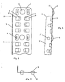
- the back-plate of which one end portion is shown in Figures l and 2 is stamped and folded out of sheet metal and comprises a plate l having a surface 2 which faces the new brickwork and a reverse surface 3 which faces the existing structure.
- the back-plate may be suitably coated, eg with an epoxy resin, or be of a suitable material, to be highly resistant to corrosion.
- the back-plate may be provided with a side flange 4 formed by folding the sheet metal at right angles to the back plate l, this flange being provided with a row with keying holes 5 for mortar, plaster or rendering. Two such side flanges at opposite sides of the back-plate or, alternatively none may be provided. Disposed along the longitudinal centre line of the back-plate is a series of fixing holes 6. These holes may be circular, or may be of rounded oblong or oval shape to provide a degree of lateral adjustability of the back-plate when fixed to a wall.
- tabs 7 Disposed longitudinally between the fixing holes 6 are three pairs of tabs 7. These tabs 7 are stamped and folded out from the back-plate l and are so adapted such that a tie (described below) can be held against the surface 2 of the back plate l.
- the tabs 7 comprises a part which extends perpendicularly from the back-plate l and a part which is parallel to the back plate l, although it can slope inwards towards the centre of the back-plate l to help keep the tie in place. It will be appreciated that a continuous tab could be provided by joining all the individual tabs together.
- the back-plate is provided with a number of "feet" 8 to maintain it in parallel spaced relation to the existing wall so that the rear surface 3 is stood off from the surface of the existing wall. This provides a space into which mortar from the new courses of bricks can enter via the holes 9 behind the tabs 7. The holes 9 are produced when the tabs 7 are stamped and folded out of the back-plate l.
- the mortar helps bond the new wall to the existing one provided there is no excessive relative vertical movement of the two walls.
- the side flanges 4 stop short of the end of the back-plate and have a rounded corner l0.
- the other end of the back-plate can be of corresponding layout with the centre part between the two ends comprising as many repeats as are necessary to achieve the desired length of the section A-B in figure l.
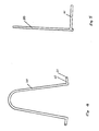
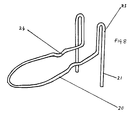
- the tie 20 comprises an approximately "U” shaped middle portion (it should be noted that unlike a conventional letter “U", the two limbs preferably converge in the direction away from the web of the "U") and with the free ends of the limbs of the "U” being bent over to form “feet” 2l which are at least approximately perpendicular to the plane of the "U” section so that they extend along the back-plate when the tie is installed.
- the feet 2l can be spaced apart from the "U" shaped middle portion by an intervening section 22. Alternatively, they are spaced apart from the "U" shaped middle portion by an ear 23 as shown in Figure 8. In the form shown in Figure 8 the feet 2l external approximately equal distances in the two opposite directions from the plane defined by the intervening central section 22.
- the tie is made of metal wire or rod material.
- one or more back-plates such as the one in Figure l are fixed to the old wall along the vertical line from which the new wall will extend. There may be a continuous or intermittent arrangement of these back-plates along this line. Alternatively one continuous back-plate may be used.
- the back-plate may be fixed to the existing structure by any suitable means such as nails, screws or bolts so as to fix the back-plate l firmly to the wall.
- a tie 20 must be fixed to the back-plate and be placed on top of the top course of bricks so far laid out in the new structure so that in the laying of the next course of bricks the tie 20 is firmly interposed between them and strongly holds these new bricks to the back-plates. This is done by squeezing the limbs 2l of the tie 20 together, if the tie is resilient, and inserting the tie 20 between a pair of tabs 7 by pushing the tie 20 perpendicularly, or at least approximately perpendicularly, towards the back plate l.
- the tie may be slid down between the pairs of tabs 7 so that the U shaped portion rests on the top course of bricks of the new structure.
- the limbs can be released, if they are resilient, so that they spring outwards to press against the vertical part of the tabs 7.
- the feet 2l are held behind successive tabs 7 and may be positioned upwards or downwards relative to the wall structures, although an upwards position is preferred so that the feet 2l do not have to be pushed into mortar associated with lower courses of bricks or blocks.
- the tie shown in Figure 8 has an indent 24 in each limb. This can provide the limbs with an extra degree of resilience or can provide a suitable means for holding the tie between a holder's thumb and forefinger.
- the tie 20 can be in a variety of positions relative to the back plates.
- the part of the central portion nearest the intervening section 22 can rest on top of a tab 7.
- the tie 20 can also be positioned such that the central portion is in an intervening position between two pairs of tabs 7.
- it can be between two adjacent pairs of tabs 7 or it can be between two pairs of tabs means 7 which are separated by a fixing hole 8.
Landscapes
- Engineering & Computer Science (AREA)
- Architecture (AREA)
- Physics & Mathematics (AREA)
- Electromagnetism (AREA)
- Civil Engineering (AREA)
- Structural Engineering (AREA)
- Finishing Walls (AREA)
- Seal Device For Vehicle (AREA)
- Confectionery (AREA)
- Window Of Vehicle (AREA)
- Connector Housings Or Holding Contact Members (AREA)
- Orthopedics, Nursing, And Contraception (AREA)
Priority Applications (1)
| Application Number | Priority Date | Filing Date | Title |
|---|---|---|---|
| AT87305922T ATE89884T1 (de) | 1986-07-03 | 1987-07-03 | Mauerverbinder. |
Applications Claiming Priority (2)
| Application Number | Priority Date | Filing Date | Title |
|---|---|---|---|
| GB8616302 | 1986-07-03 | ||
| GB868616302A GB8616302D0 (en) | 1986-07-03 | 1986-07-03 | Wall tie device |
Publications (3)
| Publication Number | Publication Date |
|---|---|
| EP0252696A2 true EP0252696A2 (fr) | 1988-01-13 |
| EP0252696A3 EP0252696A3 (en) | 1990-05-16 |
| EP0252696B1 EP0252696B1 (fr) | 1993-05-26 |
Family
ID=10600544
Family Applications (1)
| Application Number | Title | Priority Date | Filing Date |
|---|---|---|---|
| EP87305922A Expired - Lifetime EP0252696B1 (fr) | 1986-07-03 | 1987-07-03 | Dispositif de raccord mural |
Country Status (6)
| Country | Link |
|---|---|
| EP (1) | EP0252696B1 (fr) |
| AT (1) | ATE89884T1 (fr) |
| AU (1) | AU609162B2 (fr) |
| CA (1) | CA1290957C (fr) |
| DE (1) | DE3785971T2 (fr) |
| GB (2) | GB8616302D0 (fr) |
Cited By (2)
| Publication number | Priority date | Publication date | Assignee | Title |
|---|---|---|---|---|
| EP0493899A1 (fr) * | 1991-01-03 | 1992-07-08 | Allmat (East Surrey) Limited | Dispositif universel de fixation des murs |
| FR2796095A1 (fr) | 1999-07-08 | 2001-01-12 | Cogito | Caisson de boite d'attente et boite d'attente integrant un tel caisson |
Families Citing this family (1)
| Publication number | Priority date | Publication date | Assignee | Title |
|---|---|---|---|---|
| GB2229465A (en) * | 1989-03-21 | 1990-09-26 | James Savage Pritchard | Plaster panels |
Family Cites Families (6)
| Publication number | Priority date | Publication date | Assignee | Title |
|---|---|---|---|---|
| GB1157501A (en) * | 1965-09-10 | 1969-07-09 | Ilford Ltd | Photographic Colour Transfer Process. |
| GB1575501A (en) * | 1976-11-05 | 1980-09-24 | Ellidge A | Tie means for brick walls |
| GB1604941A (en) * | 1978-05-26 | 1981-12-16 | Furr D | Wall construction method |
| GB2154260B (en) * | 1984-03-15 | 1987-09-16 | Donald Furr | Wall tie device |
| GB2161515A (en) * | 1984-07-11 | 1986-01-15 | Cd Truline Ltd | Wall ties |
| GB2162216B (en) * | 1984-07-11 | 1988-09-28 | Cd Truline Ltd | Wall tying method and apparatus |
-
1986
- 1986-07-03 GB GB868616302A patent/GB8616302D0/en active Pending
-
1987
- 1987-07-03 CA CA000541223A patent/CA1290957C/fr not_active Expired - Lifetime
- 1987-07-03 AT AT87305922T patent/ATE89884T1/de active
- 1987-07-03 DE DE87305922T patent/DE3785971T2/de not_active Expired - Fee Related
- 1987-07-03 EP EP87305922A patent/EP0252696B1/fr not_active Expired - Lifetime
- 1987-07-03 GB GB8715745A patent/GB2194263B/en not_active Expired - Lifetime
-
1988
- 1988-07-28 AU AU19704/88A patent/AU609162B2/en not_active Ceased
Cited By (2)
| Publication number | Priority date | Publication date | Assignee | Title |
|---|---|---|---|---|
| EP0493899A1 (fr) * | 1991-01-03 | 1992-07-08 | Allmat (East Surrey) Limited | Dispositif universel de fixation des murs |
| FR2796095A1 (fr) | 1999-07-08 | 2001-01-12 | Cogito | Caisson de boite d'attente et boite d'attente integrant un tel caisson |
Also Published As
| Publication number | Publication date |
|---|---|
| EP0252696A3 (en) | 1990-05-16 |
| ATE89884T1 (de) | 1993-06-15 |
| GB2194263A (en) | 1988-03-02 |
| GB2194263B (en) | 1990-02-21 |
| EP0252696B1 (fr) | 1993-05-26 |
| AU1970488A (en) | 1990-02-01 |
| CA1290957C (fr) | 1991-10-22 |
| DE3785971D1 (de) | 1993-07-01 |
| DE3785971T2 (de) | 1993-12-02 |
| GB8715745D0 (en) | 1987-08-12 |
| GB8616302D0 (en) | 1986-08-13 |
| AU609162B2 (en) | 1991-04-26 |
Similar Documents
| Publication | Publication Date | Title |
|---|---|---|
| CA1285115C (fr) | Attache repliable pour profiles | |
| US4617775A (en) | Extensible reinforcing bar assembly and clip | |
| US4760677A (en) | Suspended ceiling having a concealed suspension grid and lay-in metal panels supported thereon | |
| US5509636A (en) | Retainer clip for reinforcement of concrete walls | |
| US5971329A (en) | Conduit support | |
| US4698947A (en) | Concrete wall form tie system | |
| US5658483A (en) | Corner joint tie | |
| US4783946A (en) | Supporting rail for lower ceilings and attachments | |
| US5522571A (en) | Pipe hanging strap | |
| US3782058A (en) | Tying devices for tying wooden members to composite brick and masonry walls | |
| CA2129519A1 (fr) | Support pour platre et autres enduits semblables | |
| US20030029123A1 (en) | Masonry reinforcing tie | |
| US3231944A (en) | Insulation support | |
| GB2222221A (en) | Improvements in or relating to connectors | |
| EP0159804B1 (fr) | Dispositif pour la liaison de maçonneries nouvelles et anciennes | |
| GB2125137A (en) | Attachment device | |
| US6672025B1 (en) | Curved building panel with stress-reducing apertures | |
| US4696141A (en) | Suspended ceiling having a concealed suspension grid and lay-in metal panels supported thereon | |
| EP0252696A2 (fr) | Dispositif de raccord mural | |
| GB2220430A (en) | Spacing and locating device for laying of bricks | |
| EP0113182A1 (fr) | Couverture de toit | |
| US5860261A (en) | Building block retainer apparatus | |
| EP0249478A2 (fr) | Procédé d'assemblage pour murs et dispositif | |
| EP0628668B1 (fr) | Ancrage pour maçonnerie | |
| GB2213848A (en) | Brick tie |
Legal Events
| Date | Code | Title | Description |
|---|---|---|---|
| PUAI | Public reference made under article 153(3) epc to a published international application that has entered the european phase |
Free format text: ORIGINAL CODE: 0009012 |
|
| AK | Designated contracting states |
Kind code of ref document: A2 Designated state(s): AT BE CH DE FR IT LI LU NL |
|
| PUAL | Search report despatched |
Free format text: ORIGINAL CODE: 0009013 |
|
| AK | Designated contracting states |
Kind code of ref document: A3 Designated state(s): AT BE CH DE FR IT LI LU NL |
|
| 17P | Request for examination filed |
Effective date: 19901031 |
|
| 17Q | First examination report despatched |
Effective date: 19911203 |
|
| GRAA | (expected) grant |
Free format text: ORIGINAL CODE: 0009210 |
|
| AK | Designated contracting states |
Kind code of ref document: B1 Designated state(s): AT BE CH DE FR IT LI LU NL |
|
| PG25 | Lapsed in a contracting state [announced via postgrant information from national office to epo] |
Ref country code: IT Free format text: LAPSE BECAUSE OF FAILURE TO SUBMIT A TRANSLATION OF THE DESCRIPTION OR TO PAY THE FEE WITHIN THE PRESCRIBED TIME-LIMIT;WARNING: LAPSES OF ITALIAN PATENTS WITH EFFECTIVE DATE BEFORE 2007 MAY HAVE OCCURRED AT ANY TIME BEFORE 2007. THE CORRECT EFFECTIVE DATE MAY BE DIFFERENT FROM THE ONE RECORDED. Effective date: 19930526 Ref country code: NL Effective date: 19930526 Ref country code: FR Effective date: 19930526 Ref country code: CH Effective date: 19930526 Ref country code: LI Effective date: 19930526 Ref country code: AT Effective date: 19930526 Ref country code: BE Effective date: 19930526 |
|
| REF | Corresponds to: |
Ref document number: 89884 Country of ref document: AT Date of ref document: 19930615 Kind code of ref document: T |
|
| REF | Corresponds to: |
Ref document number: 3785971 Country of ref document: DE Date of ref document: 19930701 |
|
| PG25 | Lapsed in a contracting state [announced via postgrant information from national office to epo] |
Ref country code: LU Free format text: LAPSE BECAUSE OF NON-PAYMENT OF DUE FEES Effective date: 19930731 |
|
| REG | Reference to a national code |
Ref country code: CH Ref legal event code: PL |
|
| EN | Fr: translation not filed | ||
| NLV1 | Nl: lapsed or annulled due to failure to fulfill the requirements of art. 29p and 29m of the patents act | ||
| PLBE | No opposition filed within time limit |
Free format text: ORIGINAL CODE: 0009261 |
|
| STAA | Information on the status of an ep patent application or granted ep patent |
Free format text: STATUS: NO OPPOSITION FILED WITHIN TIME LIMIT |
|
| 26N | No opposition filed | ||
| PGFP | Annual fee paid to national office [announced via postgrant information from national office to epo] |
Ref country code: DE Payment date: 19970714 Year of fee payment: 11 |
|
| PG25 | Lapsed in a contracting state [announced via postgrant information from national office to epo] |
Ref country code: DE Free format text: LAPSE BECAUSE OF NON-PAYMENT OF DUE FEES Effective date: 19990501 |