EP0252707A2 - Schottentür für Lastkraftwagen mit Kastenaufbau - Google Patents
Schottentür für Lastkraftwagen mit Kastenaufbau Download PDFInfo
- Publication number
- EP0252707A2 EP0252707A2 EP87305958A EP87305958A EP0252707A2 EP 0252707 A2 EP0252707 A2 EP 0252707A2 EP 87305958 A EP87305958 A EP 87305958A EP 87305958 A EP87305958 A EP 87305958A EP 0252707 A2 EP0252707 A2 EP 0252707A2
- Authority
- EP
- European Patent Office
- Prior art keywords
- door
- bulkhead
- trolley
- door apparatus
- rails
- Prior art date
- Legal status (The legal status is an assumption and is not a legal conclusion. Google has not performed a legal analysis and makes no representation as to the accuracy of the status listed.)
- Withdrawn
Links
- 238000010276 construction Methods 0.000 description 6
- 238000001125 extrusion Methods 0.000 description 4
- 239000004677 Nylon Substances 0.000 description 3
- 229910052751 metal Inorganic materials 0.000 description 3
- 239000002184 metal Substances 0.000 description 3
- 229920001778 nylon Polymers 0.000 description 3
- 229910000831 Steel Inorganic materials 0.000 description 2
- 239000004411 aluminium Substances 0.000 description 2
- 229910052782 aluminium Inorganic materials 0.000 description 2
- XAGFODPZIPBFFR-UHFFFAOYSA-N aluminium Chemical compound [Al] XAGFODPZIPBFFR-UHFFFAOYSA-N 0.000 description 2
- 230000008878 coupling Effects 0.000 description 2
- 238000010168 coupling process Methods 0.000 description 2
- 238000005859 coupling reaction Methods 0.000 description 2
- 238000000034 method Methods 0.000 description 2
- 239000010959 steel Substances 0.000 description 2
- 230000000694 effects Effects 0.000 description 1
- 239000006260 foam Substances 0.000 description 1
- 238000009434 installation Methods 0.000 description 1
- 238000009413 insulation Methods 0.000 description 1
- 239000000463 material Substances 0.000 description 1
- 239000004033 plastic Substances 0.000 description 1
- 229920003023 plastic Polymers 0.000 description 1
- 239000011120 plywood Substances 0.000 description 1
- 238000005057 refrigeration Methods 0.000 description 1
Images



Classifications
-
- B—PERFORMING OPERATIONS; TRANSPORTING
- B60—VEHICLES IN GENERAL
- B60P—VEHICLES ADAPTED FOR LOAD TRANSPORTATION OR TO TRANSPORT, TO CARRY, OR TO COMPRISE SPECIAL LOADS OR OBJECTS
- B60P7/00—Securing or covering of load on vehicles
- B60P7/06—Securing of load
- B60P7/135—Securing or supporting by load bracing means
- B60P7/14—Securing or supporting by load bracing means the load bracing means comprising a movable bulkhead
Definitions
- the present invention relates to a bulkhead door apparatus for a container lorry.
- Bulkhead doors are used in container lorries to subdivide the cargo space into separate smaller sections.
- the door or doors are hung within the cargo space and are movable backwards and forwards to alter the relative dimensions of the subdivisions to suit the prevailing conditions. When not in use they can be swung into the top part of the cargo space out of the way.
- the principal application of these doors is in refrigerated lorries where a lorry which is only part-loaded is subdivided in such a way as to reduce the volume which needs to be refrigerated to suit the amount of cargo being carried, and thus reduce the cost of refrigeration.
- the present invention seeks to provide an improved bulkhead door apparatus for container lorries.
- the apparatus comprises a pair of rails for attachment to the inside surfaces of the upper part of the cargo space in a container lorry, two trolleys adapted to run on said rails, a first of said trolleys pivotally mounting a bulkhead door and the second of said trolleys mounting a spring retractable roller system, and cord means extending between the door and the roller system in such a way as to take the weight of the door as it is pivoted.
- the door has two positions: a first (operative) position in which it is substantially vertical and is operable to subdivide the cargo space into two, and a second (stowage) position in which it is substantially horizontal and is positioned in the upper part of the cargo space out of the way.
- a first (operative) position in which it is substantially vertical and is operable to subdivide the cargo space into two
- a second (stowage) position in which it is substantially horizontal and is positioned in the upper part of the cargo space out of the way.
- movement is effected by pi vetting the door about its mounting points on the first of said trolleys, a substantial portion of the weight of the door being taken by the cord means which retracts as the door is raised into the stowage position.
- the two carriages move along the rails with respect to one another, being closest together when the door is in its operative position.
- the two carriages are independently movable on the rails.
- Preferably means are provided for locking the door in position so that it cannot move when the vehicle is in motion.
- this is achieved by bolt means in which a shoot is insertable into one of a number of apertures formed in a member attached to an inside surface of the cargo space. These apertures may be so spaced as to provide a large number of selectable positions for the door.
- the bolt means can be mounted on the first trolley, or on the door, or both, but preferably the shoot of the bolt means is coaxial with the axis of pivotal mounting of the door, this having the advantage that the door can be raised and lowered whilst being locked in position by the shoot.
- further bolt means may be provided to locate that end of the door remote from the pivot: in the upright position precise location is achieved by means of a further member having plural apertures therealong into which a shoot can be located.
- This further member is placed parallel to the first mentioned apertured member but lower down, at a position suitable to locate with said further bolt means.
- the further bolt means may locate in the first-mentioned apertured member, thus securing the door in the horizontal position.
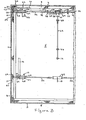
- FIG. 1 the bulkhead door apparatus is shown erected within the confines of a dotted outline representing the cargo area of a container lorry having sides 1,2, floor 3 and roof 4.
- the construction of the lorry itself is shown only diagrammatically as it does not form part of the present invention.
- the bulkhead door apparatus comprises a bulkhead door 5 which extends right across the cargo area to subdivide the same into a forward area 6, nearest the cab, and a rear area 7. Access to the forward area 6 will normally be by way of the rear doors of the lorry and the bulkhead door 5, but in some designs side doors near the front allow direct access to the forward area.
- the bulkhead door 5 will have a thermally insulating construction such as a sandwich of foam plastics material enclosed by sheets of plywood or similar.
- the thermal insulation may be further enhanced by providing brush seals 8 round the edge of the door.
- the door 5 is pivotally mounted on a trolley 9 which has four nylon wheels 10 enabling it to run on a pair of rails 11 secured to the inside surface of the sides 1,2 of the van.
- the trolley 9 is freely movable on the rails, but bolt means operated by a handle 12 are used to locate it at selected positions as will be explained hereinafter.
- a second trolley 13 has four nylon wheels 14 and is similarly freely movable on the rails 11.
- the trolley 13 mounts a retractable roller system 15 around which is wound a pair of cords 16 which are attached at their respective free ends to a lower part of the door 5.
- Further bolt means 17 operated by a handle 18 locate the door in the upright position illustrated by location of a pair of shoots in aligned apertures 30 in a pair of multi-apertured elongate members 19 attached to the sides 1,2 of the van.
- the door is shown in Figure 1 in its upright (operative) position.
- the handle 18 In order to simply raise the door to its stowage position, the handle 18 is first operated to release the bolt means 17 whereupon the door may be pulled forwards, pivotting as it does so, about the trolley 9. Upwards movement is assisted by the cords 16 which retract as they wind up into the roller system 15, thus taking part of the weight of the door as it is raised.
- the door When the door reaches the approximately horizontal position, it can be located by operating a handle (not shown) on the opposite side of the door from the handle 18 to thereby cause the bolt means 17 to lock into aligned apertures 30 in an upper multi-apertured elongate member 19. This same member is used to locate the trolley 9, as will be explained hereinafter.
- the handle 18 is first released, as before, in order to release the lower part of the door. Instead of raising the door, however, the handle 12 is now operated to release the trolley 9 and enable it, and hence the door, to be moved to a new position whereat it can be locked by releasing the handle 12 and again operating handle 18.
- the trolley 9 comprises a pair of parallel metal plates 20 joined by two hollow metal rods 21.
- Each plate 20 is formed with three upstanding tubes which are welded over corresponding holes formed in the plate.
- the upper two of these tubes one of which is shown dotted under reference 22 in Figure 3 locate the ends of respective hollow rods 21. Pins (not shown) passing through the tubes 22 and rods 21 fasten the structure together.
- the two upper tubes also locate axles 23 for the nylon wheels 10.
- the axles 23 are a sliding fit within the bore of the respective upper tubes and, as such, the wheels are able to float to cater for small imperfections in the alignment of the rails 11.
- the lower tube upstanding from plate 20 is shown dotted under reference 24 in Figure 3, but is not visible in Figure 2. It is this tube which pivotally supports the door 5; to this end the door is fitted, at each upper corner with a door pivot bracket 25.
- This bracket comprises a baseplate 26 screwed to the door surface and having upstanding ends 27. Welded into aligned apertures in the ends 27 is a length of tube 28 whose inside diameter is such as to be a sliding fit over the tube 24. The tube 28 may thus rotate about the tube 24 and thereby the door is supported and pivotted.
- a shoot 29 extends within the tube 24 and is operated by means to be described hereinafter to selectively engage an aperture 30 in the aformentioned upper multi-aperture member 19 and thus lock the trolley 9 and hence the door 5 in position. It will be noted that the shoot 24 does not have to be disengaged from its aperture 30 in order to enable the door to be pivotted about tube 24.
- each plate 20 when viewed in Figure 2 is fitted with a rubber buffer 31 to reduce the effect of impact with the trolley 13; although the two trolleys 9 and 13 are shown slightly apart in Figure 2 (for clarity), in practice, in the upright position of the door, the two trolleys will abut one another and will move apart as the door is raised.
- the two shoots 29 are operated simultaneously by pulling on the aformentioned handle 12, as will now be explained in greater detail with reference to Figure 3.
- each shoot is pivotally attached to a rod 32 which is joined to a rod 33 by a coupling means 34.
- the rod 33 is slidably mounted between saddle members 35,36 secured to the surface of door 5.
- Springs 37,38 act between saddle members 35,36 and, respectively, the coupling means 34 and a pin 39 mounted in rod 33, in order to bias the shoot 29/rod 32/rod 33 in an outwards direction - i.e. in a direction tending to lock the trolley 9.
- the saddle member 36 is located centrally of the width of the door, and a similar mechanism to that just described operates on the right-hand shoot 29 (not shown). The same references are used for consistency. It will be noted that the two rods 33 end short of one another within the saddle member 36 to allow inwards movement from the position shown.
- a link mechanism comprising two rigid link members 40 pivotally attached at one end to respective rods 33 and at the other (lower) end to a plate 41. Also attached to the plate 41 is a vertical rod 42 vcertically slidably mounted in saddle members 43,44 and having at its lower end said handle 12 fixed thereon.
- Each bolt means 17 comprises a base plate 45 attached to the door 5 and having upstanding ends 46 formed with aligned apertures. Welded into these apertures is a hollow rod 47 in which is slidably mounted a shoot 48. The shoot is able to engage in an aperture 30 in the lower member 19. Sliding movement of the shoot is effected by turning handle 18 which operates a latch mechanism 49 (not shown in detail) and causes a respective link rod 50 to be moved backwards and forwards. As already mentioned, the latch mechanism 49 is also operable from a handle positioned on the opposite side of door 5, to enable the shoots 48 to be released from the apertures 30 in the upper member 19 when the door is in the horizontal (stowage) position.
- the rod 47 provides a convenient lower attachment point for the cords 16.
- the trolley comprises a pair of parallel metal plates 51 joined by two hollow rods 52.
- each plate is formed with a pair of apertures over which are welded respective hollow rods 53.
- the external diameter of rods 53 matches the internal diameter of rods 52 so that rods 52 can slide and securely locate over the rods 53.
- Pins (not shown) are used to attach the rods 52 and 53 together.
- Rotatably mounted within rods 53 are respective axles 54 which each mount a respective wheel 14.
- the axles 54 and hence wheels 14 are able to move axially of the rods 53 to thus allow for imperfections in the alignment of track 11.
- the manner of attachment of the rods 52 to the plates 51 and the method of mounting the axles and wheels as shown in Figure 4 is identical to that used with respect to the corresponding components in the trolley 9.
- the trolley 13 mounts a retractable roller system 15 comprising a spring retractable roller 55 rotatable about an axle 56.
- the axle 56 is mounted against rotation in respective mounting brackets 57 attached to the plates 51.
- the roller 55 is of conventional construction and will not be described in detail.
- each plate 51 (when viewed in Figure 2) is fitted with a rubber buffer 58 which is positioned to abut the buffer 31 provided on the plate 20.
- the rail 11 and upper member 19 are preferably combined in a single unit which can be readily assembled into the vehicle during installation. To this end, both are mounted on a common aluminium extrusion 59 whose shape and cross section can be clearly seen in Figures 2 and 3.
- the extrusion has mounting holes (not shown) whereby it may be readily bolted or rivetted to the van sides.
- a similar technique can be used to mount the lower elongate member 19, using an intermediate aluminium extrusion shown under reference 60 which latter is formed with mounting holes (not shown) whereby it may be attached to the van sides by bolting, rivetting or the like.
Landscapes
- Engineering & Computer Science (AREA)
- Transportation (AREA)
- Mechanical Engineering (AREA)
- Support Devices For Sliding Doors (AREA)
- Fittings On The Vehicle Exterior For Carrying Loads, And Devices For Holding Or Mounting Articles (AREA)
Applications Claiming Priority (2)
| Application Number | Priority Date | Filing Date | Title |
|---|---|---|---|
| GB8616502 | 1986-07-07 | ||
| GB868616502A GB8616502D0 (en) | 1986-07-07 | 1986-07-07 | Bulkhead door apparatus |
Publications (2)
| Publication Number | Publication Date |
|---|---|
| EP0252707A2 true EP0252707A2 (de) | 1988-01-13 |
| EP0252707A3 EP0252707A3 (de) | 1988-03-30 |
Family
ID=10600674
Family Applications (1)
| Application Number | Title | Priority Date | Filing Date |
|---|---|---|---|
| EP87305958A Withdrawn EP0252707A3 (de) | 1986-07-07 | 1987-07-06 | Schottentür für Lastkraftwagen mit Kastenaufbau |
Country Status (2)
| Country | Link |
|---|---|
| EP (1) | EP0252707A3 (de) |
| GB (1) | GB8616502D0 (de) |
Cited By (17)
| Publication number | Priority date | Publication date | Assignee | Title |
|---|---|---|---|---|
| WO1989010857A3 (en) * | 1988-05-03 | 1989-12-14 | Boalloy Ltd | Van bodies |
| FR2636021A1 (fr) * | 1988-09-07 | 1990-03-09 | Malemant Bertrand | Amenagement de la caisse d'un vehicule de transport |
| EP0368077A1 (de) * | 1988-11-08 | 1990-05-16 | The Heil Co. | Müllsammelbehälter mit mehreren Kammern |
| GB2228453A (en) * | 1989-02-22 | 1990-08-29 | Global Door | Stowable bulkhead for vehicle body |
| EP0364198A3 (de) * | 1988-10-11 | 1990-10-31 | York Trailer Company Limited | Kühlfahrzeuge und -container |
| GB2238988A (en) * | 1989-09-29 | 1991-06-19 | Mark Williams Adams | Adjustable and stowable bulkhead |
| GB2241926A (en) * | 1990-01-29 | 1991-09-18 | York Trailer Co Ltd | Container or vehicle cargo restraint. |
| DE4129479A1 (de) * | 1991-09-05 | 1993-03-11 | Niesky Waggonbau Gmbh | Verbindung mittenportal und firsttraeger bei schiebewandwagen |
| GB2265358A (en) * | 1992-03-25 | 1993-09-29 | Patrick Mccann | Seal for container partition |
| GB2275896A (en) * | 1993-03-08 | 1994-09-14 | Patrick Mccann | Adjustable and stowable bulkhead for cargo container |
| US5472300A (en) * | 1992-01-31 | 1995-12-05 | Lipschitz; Larry | Apparatus for partitioning a storage space |
| DE29604366U1 (de) * | 1996-03-09 | 1996-05-09 | Kiesling Fahrzeugbau GmbH, 89160 Dornstadt | Kraftfahrzeug mit einem geschlossenen Fahrzeugaufbau |
| DE29713329U1 (de) * | 1997-07-26 | 1997-09-25 | Karosseriebau Spermann GmbH, 59368 Werne | Isoliertrennwand |
| DE29919882U1 (de) * | 1999-11-11 | 2001-03-22 | Steen, Manfred, 27211 Bassum | Klima- und Schmutzschleuse |
| USRE46663E1 (en) | 2000-07-20 | 2018-01-09 | Fg Products, Inc. | System and method for partitioning cargo areas |
| DE102016015504A1 (de) * | 2016-12-23 | 2018-06-28 | Loadlok International Bv | Trägervorrichtung für Trennwände in Frachträumen von Fahrzeugen |
| DE102022111468A1 (de) | 2022-05-09 | 2023-11-09 | Kögel Trailer GmbH | Eckwinkelprofil und Fahrzeugaufbau mit einem solchen Eckwinkelprofil |
Family Cites Families (4)
| Publication number | Priority date | Publication date | Assignee | Title |
|---|---|---|---|---|
| US3070044A (en) * | 1956-11-20 | 1962-12-25 | Evans Prod Co | Freight loading equipment |
| US3057284A (en) * | 1959-11-16 | 1962-10-09 | Robert K Learmont | Movable insulating panel for a storage unit |
| CA931429A (en) * | 1970-07-09 | 1973-08-07 | Suburban Metal Industries Limited | Bulkhead door |
| GB2153755B (en) * | 1984-02-03 | 1987-03-04 | Boalloy Ltd | Movable bulkheads |
-
1986
- 1986-07-07 GB GB868616502A patent/GB8616502D0/en active Pending
-
1987
- 1987-07-06 EP EP87305958A patent/EP0252707A3/de not_active Withdrawn
Cited By (23)
| Publication number | Priority date | Publication date | Assignee | Title |
|---|---|---|---|---|
| GB2219976A (en) * | 1988-05-03 | 1989-12-28 | Boalloy Ltd | Stowable bulkhead for van or container body |
| WO1989010857A3 (en) * | 1988-05-03 | 1989-12-14 | Boalloy Ltd | Van bodies |
| FR2636021A1 (fr) * | 1988-09-07 | 1990-03-09 | Malemant Bertrand | Amenagement de la caisse d'un vehicule de transport |
| EP0364198A3 (de) * | 1988-10-11 | 1990-10-31 | York Trailer Company Limited | Kühlfahrzeuge und -container |
| US5122025A (en) * | 1988-11-08 | 1992-06-16 | The Heil Co. | Multiple compartment body for waste products and the like |
| EP0368077A1 (de) * | 1988-11-08 | 1990-05-16 | The Heil Co. | Müllsammelbehälter mit mehreren Kammern |
| GB2228453A (en) * | 1989-02-22 | 1990-08-29 | Global Door | Stowable bulkhead for vehicle body |
| GB2238988A (en) * | 1989-09-29 | 1991-06-19 | Mark Williams Adams | Adjustable and stowable bulkhead |
| GB2241926B (en) * | 1990-01-29 | 1993-07-21 | York Trailer Co Ltd | Improvements in and relating to load restraint in vehicles and containers. |
| GB2241926A (en) * | 1990-01-29 | 1991-09-18 | York Trailer Co Ltd | Container or vehicle cargo restraint. |
| DE4129479A1 (de) * | 1991-09-05 | 1993-03-11 | Niesky Waggonbau Gmbh | Verbindung mittenportal und firsttraeger bei schiebewandwagen |
| US5472300A (en) * | 1992-01-31 | 1995-12-05 | Lipschitz; Larry | Apparatus for partitioning a storage space |
| GB2265358A (en) * | 1992-03-25 | 1993-09-29 | Patrick Mccann | Seal for container partition |
| GB2265358B (en) * | 1992-03-25 | 1994-03-23 | Patrick Mccann | Cargo containers |
| GB2275896A (en) * | 1993-03-08 | 1994-09-14 | Patrick Mccann | Adjustable and stowable bulkhead for cargo container |
| DE29604366U1 (de) * | 1996-03-09 | 1996-05-09 | Kiesling Fahrzeugbau GmbH, 89160 Dornstadt | Kraftfahrzeug mit einem geschlossenen Fahrzeugaufbau |
| DE29713329U1 (de) * | 1997-07-26 | 1997-09-25 | Karosseriebau Spermann GmbH, 59368 Werne | Isoliertrennwand |
| DE29919882U1 (de) * | 1999-11-11 | 2001-03-22 | Steen, Manfred, 27211 Bassum | Klima- und Schmutzschleuse |
| EP1099598A3 (de) * | 1999-11-11 | 2004-01-28 | Manfred Steen | Platte für Klima- und Schmutz |
| USRE46663E1 (en) | 2000-07-20 | 2018-01-09 | Fg Products, Inc. | System and method for partitioning cargo areas |
| DE102016015504A1 (de) * | 2016-12-23 | 2018-06-28 | Loadlok International Bv | Trägervorrichtung für Trennwände in Frachträumen von Fahrzeugen |
| DE102022111468A1 (de) | 2022-05-09 | 2023-11-09 | Kögel Trailer GmbH | Eckwinkelprofil und Fahrzeugaufbau mit einem solchen Eckwinkelprofil |
| DE102022111468B4 (de) * | 2022-05-09 | 2026-01-15 | Kögel Trailer GmbH | Kühlfahrzeugaufbau mit einem Eckwinkelprofil |
Also Published As
| Publication number | Publication date |
|---|---|
| EP0252707A3 (de) | 1988-03-30 |
| GB8616502D0 (en) | 1986-08-13 |
Similar Documents
| Publication | Publication Date | Title |
|---|---|---|
| EP0252707A2 (de) | Schottentür für Lastkraftwagen mit Kastenaufbau | |
| US6340190B1 (en) | Tailgate attachment for extending the cargo space of a vehicle | |
| US4645230A (en) | Collapsible trailer | |
| US5121959A (en) | Slide mount for pick-up truck toolboxes | |
| US5328192A (en) | Manual pull-type carrier for transporting a large game carcass | |
| CA2076255A1 (en) | Vehicle attachment for transporting snowmobiles | |
| US9090197B2 (en) | Hitch mounted camping assembly | |
| CA2607008C (en) | Clamp-on material carrier for a panel truck | |
| US4397476A (en) | Collapsible trailer | |
| US7243979B1 (en) | Recreational and utility trailer | |
| US9266458B2 (en) | Foldable extension deck and ramp assembly for pickup truck | |
| US4034879A (en) | Device for loading and carrying boats on top of vehicles | |
| US3806147A (en) | Mobile building | |
| US20180257577A1 (en) | Rear Loading, Drop Down Ladder Rack System & Method Of Use | |
| US20030080576A1 (en) | Straight motion parallelogram linkage | |
| US4170379A (en) | Carriage insertable into the load space of a motor vehicle | |
| US3368839A (en) | Expandable camper | |
| US3289225A (en) | Convertible trailer and pontoon boat construction | |
| CA2823938C (en) | Foldable extension deck and ramp assembly for pickup truck | |
| US20100206929A1 (en) | Lightweight cargo carrier for vehicles | |
| US5183282A (en) | Trailered cradle and boat/yacht managing method | |
| US11623556B2 (en) | Retractable cover for a boat trailer | |
| US3417890A (en) | Trailer for towing cars | |
| US20050036870A1 (en) | Loading and transporting system | |
| US2233181A (en) | Automobile body |
Legal Events
| Date | Code | Title | Description |
|---|---|---|---|
| PUAI | Public reference made under article 153(3) epc to a published international application that has entered the european phase |
Free format text: ORIGINAL CODE: 0009012 |
|
| AK | Designated contracting states |
Kind code of ref document: A2 Designated state(s): DE FR GB NL |
|
| PUAL | Search report despatched |
Free format text: ORIGINAL CODE: 0009013 |
|
| AK | Designated contracting states |
Kind code of ref document: A3 Designated state(s): DE FR GB NL |
|
| 17P | Request for examination filed |
Effective date: 19880816 |
|
| 17Q | First examination report despatched |
Effective date: 19881222 |
|
| STAA | Information on the status of an ep patent application or granted ep patent |
Free format text: STATUS: THE APPLICATION IS DEEMED TO BE WITHDRAWN |
|
| 18D | Application deemed to be withdrawn |
Effective date: 19890703 |
|
| RIN1 | Information on inventor provided before grant (corrected) |
Inventor name: DOVER, DONALD HENRYWILLIAM |