EP0252839A2 - Vorrichtung zum mindestens teilweise Schliessen einer vertikalen Gebäudeöffnung; Anwendung als mechanische Frostschutzabsperrung - Google Patents
Vorrichtung zum mindestens teilweise Schliessen einer vertikalen Gebäudeöffnung; Anwendung als mechanische Frostschutzabsperrung Download PDFInfo
- Publication number
- EP0252839A2 EP0252839A2 EP87401595A EP87401595A EP0252839A2 EP 0252839 A2 EP0252839 A2 EP 0252839A2 EP 87401595 A EP87401595 A EP 87401595A EP 87401595 A EP87401595 A EP 87401595A EP 0252839 A2 EP0252839 A2 EP 0252839A2
- Authority
- EP
- European Patent Office
- Prior art keywords
- curtain
- transducer
- chain
- dynamometric
- aforementioned
- Prior art date
- Legal status (The legal status is an assumption and is not a legal conclusion. Google has not performed a legal analysis and makes no representation as to the accuracy of the status listed.)
- Withdrawn
Links
Images


Classifications
-
- E—FIXED CONSTRUCTIONS
- E06—DOORS, WINDOWS, SHUTTERS, OR ROLLER BLINDS IN GENERAL; LADDERS
- E06B—FIXED OR MOVABLE CLOSURES FOR OPENINGS IN BUILDINGS, VEHICLES, FENCES OR LIKE ENCLOSURES IN GENERAL, e.g. DOORS, WINDOWS, BLINDS, GATES
- E06B9/00—Screening or protective devices for wall or similar openings, with or without operating or securing mechanisms; Closures of similar construction
- E06B9/56—Operating, guiding or securing devices or arrangements for roll-type closures; Spring drums; Tape drums; Counterweighting arrangements therefor
- E06B9/68—Operating devices or mechanisms, e.g. with electric drive
-
- E—FIXED CONSTRUCTIONS
- E06—DOORS, WINDOWS, SHUTTERS, OR ROLLER BLINDS IN GENERAL; LADDERS
- E06B—FIXED OR MOVABLE CLOSURES FOR OPENINGS IN BUILDINGS, VEHICLES, FENCES OR LIKE ENCLOSURES IN GENERAL, e.g. DOORS, WINDOWS, BLINDS, GATES
- E06B9/00—Screening or protective devices for wall or similar openings, with or without operating or securing mechanisms; Closures of similar construction
- E06B9/02—Shutters, movable grilles, or other safety closing devices, e.g. against burglary
- E06B9/08—Roll-type closures
- E06B9/11—Roller shutters
- E06B9/13—Roller shutters with closing members of one piece, e.g. of corrugated sheet metal
-
- E—FIXED CONSTRUCTIONS
- E06—DOORS, WINDOWS, SHUTTERS, OR ROLLER BLINDS IN GENERAL; LADDERS
- E06B—FIXED OR MOVABLE CLOSURES FOR OPENINGS IN BUILDINGS, VEHICLES, FENCES OR LIKE ENCLOSURES IN GENERAL, e.g. DOORS, WINDOWS, BLINDS, GATES
- E06B9/00—Screening or protective devices for wall or similar openings, with or without operating or securing mechanisms; Closures of similar construction
- E06B9/56—Operating, guiding or securing devices or arrangements for roll-type closures; Spring drums; Tape drums; Counterweighting arrangements therefor
- E06B9/58—Guiding devices
-
- G—PHYSICS
- G21—NUCLEAR PHYSICS; NUCLEAR ENGINEERING
- G21D—NUCLEAR POWER PLANT
- G21D1/00—Details of nuclear power plant
- G21D1/02—Arrangements of auxiliary equipment
-
- E—FIXED CONSTRUCTIONS
- E06—DOORS, WINDOWS, SHUTTERS, OR ROLLER BLINDS IN GENERAL; LADDERS
- E06B—FIXED OR MOVABLE CLOSURES FOR OPENINGS IN BUILDINGS, VEHICLES, FENCES OR LIKE ENCLOSURES IN GENERAL, e.g. DOORS, WINDOWS, BLINDS, GATES
- E06B9/00—Screening or protective devices for wall or similar openings, with or without operating or securing mechanisms; Closures of similar construction
- E06B9/02—Shutters, movable grilles, or other safety closing devices, e.g. against burglary
- E06B9/08—Roll-type closures
- E06B9/11—Roller shutters
- E06B9/15—Roller shutters with closing members formed of slats or the like
- E06B2009/1577—Slat end pieces used for guiding shutter
- E06B2009/1594—Slat end pieces used for guiding shutter attached to outer surface of slat
-
- Y—GENERAL TAGGING OF NEW TECHNOLOGICAL DEVELOPMENTS; GENERAL TAGGING OF CROSS-SECTIONAL TECHNOLOGIES SPANNING OVER SEVERAL SECTIONS OF THE IPC; TECHNICAL SUBJECTS COVERED BY FORMER USPC CROSS-REFERENCE ART COLLECTIONS [XRACs] AND DIGESTS
- Y02—TECHNOLOGIES OR APPLICATIONS FOR MITIGATION OR ADAPTATION AGAINST CLIMATE CHANGE
- Y02E—REDUCTION OF GREENHOUSE GAS [GHG] EMISSIONS, RELATED TO ENERGY GENERATION, TRANSMISSION OR DISTRIBUTION
- Y02E30/00—Energy generation of nuclear origin
- Y02E30/30—Nuclear fission reactors
Definitions
- the present invention relates to an at least partial closure device for a vertical opening in a building such as for example a large hangar door.
- the invention finds particular application for mechanical frost protection, in particular for protecting the interior of the dispersion zone of an atmospheric cooling tower for a nuclear power plant.
- a transversely rigid and longitudinally flexible continuous curtain such as in particular a unidirectionally corrugated curtain
- two lateral guide tracks each comprising a vertical portion for rectilinear translation of at least partial closing and of bay opening, and movement controlled.
- the curtain is usually wound for the opening of the passage opening, in one or more turns on a drive support such as a cylinder or a drum.
- the object of the present invention is to obtain a system of a simpler design allowing in particular an easy storage of the curtain and avoiding any deformation in its vertical position by its own weight or under the effect of a temporary overload. such as ice.
- the solution according to the present invention to achieve this objective consists of a device for at least partial closure of a vertical bay in a building by a transversely rigid and longitudinally flexible continuous curtain, such as in particular a unidirectionally corrugated curtain, with bilateral guidance by two lateral guide paths each comprising a vertical portion for rectilinear translation of at least partial closing and opening of bay, and with controlled movement, the guide tracks each comprising an upper portion for rectilinear translation of storage, connected to the vertical portion by an arcuate intermediate portion and characterized in that the curtain is supported on each side by a roller curtain curtain chain of bearings movable in the corresponding lateral guide path, fixed to the edge of the curtain and extending over at least the entire length of the curtain.
- each curtain-carrying chain is associated with a flexible endless drive transmission member such as a cable or chain extending horizontally and externally to the curtain by passing over two respectively respectively endless return pulleys and driven and preferably comprising a tensioning means.
- a flexible endless drive transmission member such as a cable or chain extending horizontally and externally to the curtain by passing over two respectively respectively endless return pulleys and driven and preferably comprising a tensioning means.
- the present invention also relates to the application of the closure device described above for antifreeze sealing to protect in particular the interior of the dispersion zone of an atmospheric cooling tower of a nuclear power station, where the water from hot refrigeration is cooled for recycling by heat exchange with the outside air.
- the cold outside air causes ice to form on all or part of the dispersion zone and the ice wall thus formed limits the entry of air necessary for heat exchange.
- the device according to the invention makes it possible on the one hand to avoid or limit the formation of ice during the cold period when the opening is at least partially closed while allowing heat exchange with the outside air, and d 'on the other hand to easily return to normal operating conditions upon return to positive temperatures.
- the present invention therefore also aims to eliminate the above drawbacks by proportioning an at least partial closure device for a vertical opening in a building by a continuous curtain which is transversely rigid and longitudinally flexible and characterized in that the means of control is a floating mounted irreversible motor-reducer and in that it comprises a compound force limiter associated with the motor-reducer and comprising a dynamometric transducer adapted to stop the motor-reducer when an force opposing the controlled movement reached a predetermined threshold value defined by the transducer.
- the above-mentioned compound force limiter further comprises a dynamometric axis connected to the dynamometric transducer and controlling the gear motor so as to descend the curtain towards its fully closed position when the overload applied to the curtain at the fixed partially closed position exceeds a predetermined threshold value defined by the dynamometric axis and lower than the predetermined threshold value defined by the dynamometric transducer .
- the closure device comprises a curtain 1 with bilateral guidance and with controlled movement.
- the curtain 1 is preferably produced in the form of a metallic sheet (for example made of aluminum alloy) wavy with waves or ribs of substantially trapezoidal cross section (FIGS. 4 and 7).
- This ply combines great transverse rigidity, making it possible in particular to resist overloads due to the wind over large spans, with a longitudinal elasticity making it possible to maintain easy operation in curved passages of reduced radius.
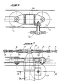
- the curtain 1 is supported on each side by a curtain-carrying chain 2 composed of carriages 3 with two successive rollers 4, 4a forming links respectively fixed to the curtain 1 by means of rigid fixing elements such as transverse plates 5, for example in U, welded to the curtain 1 ( Figures 3, 4 and 8).
- the carriages 3 of each chain are connected to each other by two intermediate connecting links 6 on which are fixed other transverse elements 7 for fixing to the curtain 1.
- rollers 4, 4a of each chain can be moved in a lateral guide path 9 corresponding, outside the curtain 1.
- the curtain 1 is further guided laterally by rollers or transverse guide shoes 10 cooperating with conjugate lateral paths of transverse guide 11.
- rollers 10 are fixed, for example by screwing, on the underside of the curtain 1 and of the chains 2 by means of the fixing elements 5 and 7.
- the lateral 9 and transverse 11 guide tracks are fixed to one another and produced in the form of a suitable profile, for example of T-shaped cross section (FIG. 3).
- Each curtain-carrying chain 2 extends beyond the upper end 12 of the curtain 1.
- the two chains are joined together in their extension by at least one cross-member 13 whose end cross-member 13e is bilaterally connected respectively to its ends opposite to the curtain drive system ( Figure 1, 5 and 6).
- Each spacer crosspiece connects two corresponding carriages of the two chains 2 and preferably carries a roller or transverse guide shoe 14 in the vicinity of its ends ( Figure 8).
- Each curtain-carrying chain 2 is associated with a flexible endless drive transmission member such as cable or chain 15, extending horizontally and externally to the curtain 1. As shown in FIG. 1, each drive chain 15 passes On two leading and return pulleys 16 and driven 17 respectively.
- the driving pulleys 16 are interconnected by a transverse axis 8 driven in rotation by an appropriate control means such as an irreversible gear motor 18, for example of the screwless type thin, mounted floating, that is to say supported directly on the transverse shaft 8.
- Each drive chain 15 preferably comprises a tensioning means 19 constituted by a set of three pulleys 20 arranged in a triangle, the lowest of which is integral with a counterweight 21.
- Each curtain-holder chain 2 is connected to a corresponding drive chain 15, at the level of the end driving cross member 13e (FIGS. 1, 5 and 6).
- the cross-member 13e is connected by its two ends to each drive chain 15 by a bilateral elastic connection in the direction of the drive traction force.
- This bilateral elastic connection comprises a rod 23 freely slidingly passing through the end of the driving cross-member 13e and comprises a pair of antagonistic springs 24, 25 situated respectively on either side of said cross-member, taking respectively support against the latter under compression preload.
- the rod 23 is interposed in the drive transmission member 15 of which it is an integral part.
- the rod 23 has a non-threaded central portion extending on each side by a threaded part for its attachment to the chain 15 via a threaded bushing tenon 26 which attaches to the end of the rod more or less deeply.
- the springs 24 and 25 are preloaded in an adjustable manner by means of threaded sleeves 27 forming stops, locked by lock nut 28.
- the drive transmission chains 15, driven in rotation by means of the motor 18 drive the curtain 1 through the end spacer 13e in the closed or open position of the opening according to the direction of rotation of the motor. .
- the curtain 1 is guided bilaterally by the two lateral and transverse guide paths 9 and 11 following a path comprising a vertical portion for rectilinear translation of at least partial closing and opening of the opening, an upper portion for rectilinear translation for storing the curtain 1, connected to said vertical portion by an arcuate intermediate portion.
- each lateral guide path ends with a stop 31.
- the bilateral elastic connection 29 At the start of the closing stroke, the spring 25 is progressively compressed against the ends of the end cross member 13e, thus allowing a gradual and damped start of the curtain. 1.
- the links of the chain 2 are positioned slightly in a zig-zag due to the clearance left between the rollers and the raceways.
- the chain 15 continues its movement, by decompressing the spring 24, and the movement is stopped when the equilibrium position of the springs 24 and 25 is achieved. This eliminates any effort in the control chain 15 due to the own weight of the curtain and possibly to the additional weight (such as for example the ice coming to accumulate on the curtain) by further packing the zig-zag setting of the links of the chain 2.
- the reverse process is carried out during the opening operation.
- FIG. 2 shows an application of the closure device described above, as an anti-freeze mechanical shutter intended in particular to protect the interior of the dispersion zone of an atmospheric cooling tower for a power station. nuclear.
- this tower is surrounded at the base of a cylindrical ring carrying a basin in the open air 32 in which the cooling water arrives at a temperature of about 38 ° C.
- a dispersion structure formed from horizontal plastic slats 34 hung on vertical stainless steel trellis suspended from the upper basin 32.
- the hot water drops in this dispersion zone thanks to sprinklers provided in the bottom of the basin.
- a current of fresh air (F) coming from outside the tower crosses the path of the water which falls through the dispersing device thus ensuring a heat exchange.
- the aerodynamic flow of air is facilitated by fixed louvers 33 arranged at the periphery of the tower. After dispersion, the water cooled to 28 ° C. is recycled.
- the closure device according to the invention is arranged outside the cooling tower, and prevents cold air from passing directly inside the tower. Very little gel is thus formed and the operation of the tower remains normal even when the outside air is very cold. The cost-effectiveness of refrigeration is thus appreciably increased, the more so as the device according to the invention makes it possible to speed up any thawing inside the tower.
- the design of the closure device makes it possible to modulate the closed surface as a function of temperature variations and prevailing winds.
- the invention further comprises, as shown in FIGS. 1, 9 and 10, a compound force limiting device 40 disposed at the output of the geared motor 18 and comprising a dynamometric transducer 41, such as for example the transducer known under the name DYNASTAT ( registered trademark), and having one of its ends in the form of a yoke (41a) hingedly connected to the lower end of a reaction arm 42 traversed by the transverse shaft 8 and secured to the frame of the gear motor 18 using appropriate means (not shown), such as for example fixing screws.
- a compound force limiting device 40 disposed at the output of the geared motor 18 and comprising a dynamometric transducer 41, such as for example the transducer known under the name DYNASTAT ( registered trademark), and having one of its ends in the form of a yoke (41a) hingedly connected to the lower end of a reaction arm 42 traversed by the transverse shaft 8 and secured to the frame of the gear motor 18 using appropriate means (not shown),
- the limiter device 40 further comprises a device forming a dynamometric axis 43 mounted on the yoke end 41b of the transducer 41 opposite to that connected to the reaction arm 42.
- the device forming a dynamometric axis 43 comprises strain gauges 44 measuring the shear stresses in the dynamometric axis prorement said 45.
- the axis 45 is locked in rotation by a stop plate 46 secured to a fixed support 47 outside the system.
- the axis 45 is mounted inside the fixed support 47 as can be seen in FIG. 3.
- the dynamometric axis device 43 also includes an electronic circuit, known per se, bearing the reference 48 and associated with the shaft 45 for produce at the output S an electrical signal representative of the exceeding of a limit overload value, as will be described later.
- the geared motor 18 controls, via the drive system, the movement of the curtain 1, for example from its position for closing the opening, as shown in FIG. 1, to its horizontal storage position. Due to the floating mounting of the gear motor 18, a force response to the force provided by the gear motor 18 to move the curtain 1 is applied to the reaction arm 42. This reaction force is transmitted to the torque transducer in which electrical switches are arranged intended to stop the gear motor 18 when the reaction force, which is a traction or compression force in the direction of movement of the curtain 1, reaches a predetermined threshold value.
- the curtain 1 In order to modulate the air inlet as a function of the outside temperature, the curtain 1 is stopped at an intermediate fixed position of selectively adjustable partial closure, the selection of the intermediate positions being able for example to be carried out by counting the number of turns of the shaft 8 using an optical or mechanical device. At each of these intermediate positions, the weight of the curtain is directly supported by the curtain chains and therefore by the transmission system. However, during the winter periods, ice formations can indiscriminately overload the curtain 1 in the intermediate fixed position, this overload can cause the transmission system to break.
- the dynamometric axis device 43 is adapted to receive, via the reaction arm 42, the force applied to the transmission system 15 by the weights of the curtain 1 and of the glass formed thereon.
- the overload When the overload reaches a predetermined threshold value defined by the device forming the dynamometric axis 43, the latter produces an electrical signal for controlling the geared motor 18 so as to descend the curtain to the position of complete closure of the bay, position at which the curtain is in abutment on the lower stops 31.
- the descent of the curtain 1 takes place when the ice load on the curtain 1 reaches 1186 daN.
- the electronic circuit 48 of the device forming the dynamometric axis is tared at the factory to a value corresponding for example to 1186 daN of ice.
Landscapes
- Engineering & Computer Science (AREA)
- Structural Engineering (AREA)
- Architecture (AREA)
- Civil Engineering (AREA)
- Physics & Mathematics (AREA)
- Plasma & Fusion (AREA)
- General Engineering & Computer Science (AREA)
- High Energy & Nuclear Physics (AREA)
- Operating, Guiding And Securing Of Roll- Type Closing Members (AREA)
Applications Claiming Priority (4)
| Application Number | Priority Date | Filing Date | Title |
|---|---|---|---|
| FR8610019A FR2601411B1 (fr) | 1986-07-09 | 1986-07-09 | Dispositif de fermeture au moins partielle d'une baie verticale dans un batiment; son application comme obturateur mecanique antigel |
| FR8610019 | 1986-07-09 | ||
| FR8709247 | 1987-06-30 | ||
| FR878709247A FR2617532B2 (fr) | 1987-06-30 | 1987-06-30 | Dispositif de fermeture au moins partielle d'une baie verticale dans un batiment |
Publications (2)
| Publication Number | Publication Date |
|---|---|
| EP0252839A2 true EP0252839A2 (de) | 1988-01-13 |
| EP0252839A3 EP0252839A3 (de) | 1988-06-01 |
Family
ID=26225383
Family Applications (1)
| Application Number | Title | Priority Date | Filing Date |
|---|---|---|---|
| EP87401595A Withdrawn EP0252839A3 (de) | 1986-07-09 | 1987-07-07 | Vorrichtung zum mindestens teilweise Schliessen einer vertikalen Gebäudeöffnung; Anwendung als mechanische Frostschutzabsperrung |
Country Status (3)
| Country | Link |
|---|---|
| US (1) | US4811777A (de) |
| EP (1) | EP0252839A3 (de) |
| CA (1) | CA1288041C (de) |
Cited By (6)
| Publication number | Priority date | Publication date | Assignee | Title |
|---|---|---|---|---|
| EP0371527A1 (de) * | 1988-12-01 | 1990-06-06 | Polynorm N.V. | Tür |
| WO1995030064A1 (fr) * | 1994-04-29 | 1995-11-09 | Dynaco International | Dispositif de fermeture a rideau souple |
| BE1008321A3 (fr) * | 1994-04-29 | 1996-04-02 | Dynaco International Sa | Dispositif de fermeture a rideau souple. |
| EP0839986A1 (de) * | 1996-11-02 | 1998-05-06 | Chain-Tech International Corp. | Türzusammenbau mit einem vertikal bewegbaren Türladen |
| FR3006753A1 (fr) * | 2013-06-11 | 2014-12-12 | Jacir | Tour de refroidissement a parois laterales souples |
| FR3013859A1 (fr) * | 2013-11-22 | 2015-05-29 | Somfy Sas | Procede de commande d'une installation exposee aux intemperies, et installation domotique associee |
Families Citing this family (18)
| Publication number | Priority date | Publication date | Assignee | Title |
|---|---|---|---|---|
| US5277240A (en) * | 1990-04-24 | 1994-01-11 | Tebel Pneumatiek B.V. | Overhead door assembly |
| US5394923A (en) * | 1993-05-17 | 1995-03-07 | Danziger; Jordan | Resilient barrier gate |
| SE506390C2 (sv) * | 1996-05-07 | 1997-12-08 | Megadoor Ab | Anordning och förfarande vid manövrering av ett objekt t ex port |
| US5738161A (en) * | 1996-09-09 | 1998-04-14 | Diesel Equipment Limited | Roll up door |
| DE102004055740A1 (de) * | 2004-06-09 | 2006-01-05 | Liebherr-Aerospace Lindenberg Gmbh | Flugzeughochauftriebssystem mit Überlastsicherung |
| FR2880740B1 (fr) * | 2005-01-11 | 2007-04-27 | Somfy Sas | Actionneur a moteur a courant continu et a transmission irreversible pour la manoeuvre d'un volet roulant |
| US8037921B2 (en) | 2006-06-05 | 2011-10-18 | Rite-Hite Holding Corporation | Track and guide system for a door |
| US20070277943A1 (en) * | 2006-06-05 | 2007-12-06 | Rite-Hite Holding Corporation | Track and guide system for a door |
| US7748431B2 (en) | 2006-06-05 | 2010-07-06 | Rite-Hite Holding Corporation | Track and guide system for a door |
| US8365801B1 (en) | 2009-07-23 | 2013-02-05 | Motosko Stephen J | Roll-up/down storm shutter having corrugated shutter slats |
| US9267326B2 (en) | 2013-04-22 | 2016-02-23 | Mckeon Rolling Steel Door Company, Inc. | Drive assisted roller assembly for rolling door |
| BE1023551B1 (nl) * | 2015-10-30 | 2017-05-02 | Renson Sunprotection Screens N.V. | Scherminrichting |
| US10385600B2 (en) * | 2016-05-11 | 2019-08-20 | Contour Closures, Inc. | Horizontal garage door assembly |
| SI3263820T1 (sl) * | 2016-06-28 | 2019-02-28 | Gabrijel Rejc | Motorno gnana in navpično premična dvižna vrata |
| EP3263819B1 (de) * | 2016-06-28 | 2018-12-19 | Gabrijel Rejc | Vertikal bewegbares tor mit einem torblatt |
| DE102016225079A1 (de) | 2016-12-15 | 2018-06-21 | Gabrijel Rejc Gmbh & Co. Kg | Tor mit einer Absturzsicherung |
| KR102265370B1 (ko) * | 2019-10-15 | 2021-06-15 | 강성배 | 무동력 개폐 방화 셔터 |
| CN117158759B (zh) * | 2023-10-10 | 2024-06-11 | 广东常明机电有限公司 | 电动窗帘的窗帘收放装置以及电动窗帘 |
Family Cites Families (17)
| Publication number | Priority date | Publication date | Assignee | Title |
|---|---|---|---|---|
| DE387600C (de) * | 1920-11-14 | 1924-01-04 | Otto Rastaedt | Rollenfuehrung fuer Rollschutzgitter |
| US1936300A (en) * | 1932-06-11 | 1933-11-21 | John H Guss | Metal door |
| US2789636A (en) * | 1954-08-30 | 1957-04-23 | Julius J Lawick | Door operating mechanism |
| US2909718A (en) * | 1955-08-26 | 1959-10-20 | Julius J Lawick | Door operating apparatus |
| US2947354A (en) * | 1956-02-17 | 1960-08-02 | Creusot Forges Ateliers | Movable panel |
| US2920151A (en) * | 1957-01-24 | 1960-01-05 | Julius J Lawick | Door operating electric switch |
| NL244394A (de) * | 1958-10-17 | |||
| US3129040A (en) * | 1962-10-19 | 1964-04-14 | Rose James De | Cabinet having an electrically operated closure |
| US3166306A (en) * | 1963-07-18 | 1965-01-19 | Astrotec Inc | Garage door operator |
| BE650567A (de) * | 1964-07-15 | 1965-01-15 | ||
| DE2036560A1 (de) * | 1970-07-23 | 1972-02-03 | Himmelmann & Hoffmann, 4620 Castrop Rauxel | Vorrichtung zum selbsttätigen Offnen und Schließen von Toren, Fenstern, Klappen oddgl |
| US3981343A (en) * | 1974-09-23 | 1976-09-21 | Arthur M. Brady | Counterbalancing mechanism for rolling doors |
| US4341253A (en) * | 1979-11-12 | 1982-07-27 | Anton Eyerle | Cover arrangement for servicing holes |
| DE3021310A1 (de) * | 1980-06-06 | 1981-12-17 | Karl 3151 Woltorf Osthushenrich | Tor, insbesondere garagentor |
| DE3347265A1 (de) * | 1983-12-28 | 1985-07-11 | Rollwände- & Jalousienfabrik C. Behrens GmbH & Co, 3000 Hannover | Sektionaltor |
| DE3408080A1 (de) * | 1984-03-05 | 1985-09-05 | Rhein-Bayern-Fahrzeugbau GmbH & Co KG, 8950 Kaufbeuren | Abdeckung fuer montagegruben |
| CA1260025A (en) * | 1985-11-14 | 1989-09-26 | M & I Door Systems Limited | Apparatus for opening and closing industrial door |
-
1987
- 1987-07-07 CA CA000541513A patent/CA1288041C/en not_active Expired - Lifetime
- 1987-07-07 EP EP87401595A patent/EP0252839A3/de not_active Withdrawn
- 1987-07-08 US US07/070,971 patent/US4811777A/en not_active Expired - Fee Related
Cited By (7)
| Publication number | Priority date | Publication date | Assignee | Title |
|---|---|---|---|---|
| EP0371527A1 (de) * | 1988-12-01 | 1990-06-06 | Polynorm N.V. | Tür |
| WO1995030064A1 (fr) * | 1994-04-29 | 1995-11-09 | Dynaco International | Dispositif de fermeture a rideau souple |
| BE1008321A3 (fr) * | 1994-04-29 | 1996-04-02 | Dynaco International Sa | Dispositif de fermeture a rideau souple. |
| US6119758A (en) * | 1994-04-29 | 2000-09-19 | Dynaco International | Closure device with a flexible screen |
| EP0839986A1 (de) * | 1996-11-02 | 1998-05-06 | Chain-Tech International Corp. | Türzusammenbau mit einem vertikal bewegbaren Türladen |
| FR3006753A1 (fr) * | 2013-06-11 | 2014-12-12 | Jacir | Tour de refroidissement a parois laterales souples |
| FR3013859A1 (fr) * | 2013-11-22 | 2015-05-29 | Somfy Sas | Procede de commande d'une installation exposee aux intemperies, et installation domotique associee |
Also Published As
| Publication number | Publication date |
|---|---|
| US4811777A (en) | 1989-03-14 |
| CA1288041C (en) | 1991-08-27 |
| EP0252839A3 (de) | 1988-06-01 |
Similar Documents
| Publication | Publication Date | Title |
|---|---|---|
| EP0252839A2 (de) | Vorrichtung zum mindestens teilweise Schliessen einer vertikalen Gebäudeöffnung; Anwendung als mechanische Frostschutzabsperrung | |
| EP3438371A1 (de) | Anpassbare pergola | |
| EP3390743B1 (de) | Gebäude mit einer autonom beweglichen mobilen sonnenblende | |
| FR2494957A1 (fr) | Appareil d'enroulement et de deroulement d'un ecran souple de couverture d'une serre | |
| EP0221829B1 (de) | Rolladen für Dachfenster | |
| FR2601411A1 (fr) | Dispositif de fermeture au moins partielle d'une baie verticale dans un batiment; son application comme obturateur mecanique antigel | |
| EP3164351A1 (de) | Vorrichtung zum schleppen eines sehr langen rohrförmigen objekts | |
| EP0103559B1 (de) | Beweglicher Lüftungsdachfirst aus Polyester zur Belüftung von Ställen | |
| FR2673236A1 (fr) | Dispositif de securite pour portes a rideau relevable. | |
| FR2617532A2 (fr) | Dispositif de fermeture au moins partielle d'une baie verticale dans un batiment | |
| FR2679591A1 (fr) | Dispositif de commande electromecanique pour porte basculante, notamment pour porte basculante de garage. | |
| EP3269896B1 (de) | Rollladen mit verstellbaren lamellen | |
| FR2542360A1 (fr) | Dispositif de trappe mobile notamment pour le desenfumage | |
| FR2678414A1 (fr) | Dispositif a panneau pivotant pour presenter une information. | |
| EP1260135A1 (de) | Vorrichtung zum reversiblen Abdecken eines Gewächshausdaches mit einer Plane | |
| FR2639080A1 (fr) | Organe d'entrainement a longue course pour une installation de pompage a tiges pour puits, notamment de petrole | |
| EP0068969B1 (de) | Rauchabzugseinrichtung insbesonder für oeffentliche oder industrielle Gebaeude | |
| EP0994219A1 (de) | Überströmtes Wehr mit kippbarer Wehrklappe | |
| FR2957114A1 (fr) | Volet d'occultation d'un ouvrant d'un batiment, et utilisation d'un tel volet | |
| FR2664324A1 (fr) | Dispositif d'entrainement d'un volet roulant en position horizontale ou a faible pente. | |
| FR2755996A1 (fr) | Dispositif de manoeuvre de jalousies a effort assiste | |
| FR2509363A1 (fr) | Dispositif d'occultation a lames paralleles coulissantes et orientables a commande electro-mecanique pour baies vitrees verticales, horizontales ou inclinees de grandes dimensions | |
| FR2467952A1 (fr) | Porte coulissante | |
| EP1739274A1 (de) | Vorrichtung zur Absturzsicherung für ein Industrietor | |
| FR2815514A1 (fr) | Dispositif d'enroulement et de deploiement d'un film plastique pour ouverture de serre |
Legal Events
| Date | Code | Title | Description |
|---|---|---|---|
| PUAI | Public reference made under article 153(3) epc to a published international application that has entered the european phase |
Free format text: ORIGINAL CODE: 0009012 |
|
| AK | Designated contracting states |
Kind code of ref document: A2 Designated state(s): CH DE LI NL |
|
| PUAL | Search report despatched |
Free format text: ORIGINAL CODE: 0009013 |
|
| AK | Designated contracting states |
Kind code of ref document: A3 Designated state(s): CH DE LI NL |
|
| 17P | Request for examination filed |
Effective date: 19880702 |
|
| 17Q | First examination report despatched |
Effective date: 19890220 |
|
| STAA | Information on the status of an ep patent application or granted ep patent |
Free format text: STATUS: THE APPLICATION IS DEEMED TO BE WITHDRAWN |
|
| 18D | Application deemed to be withdrawn |
Effective date: 19900301 |
|
| RIN1 | Information on inventor provided before grant (corrected) |
Inventor name: CHRETIEN, MICHEL JEAN EMILE |