EP0252868A2 - Outil pour élargir les tubes - Google Patents
Outil pour élargir les tubes Download PDFInfo
- Publication number
- EP0252868A2 EP0252868A2 EP87630043A EP87630043A EP0252868A2 EP 0252868 A2 EP0252868 A2 EP 0252868A2 EP 87630043 A EP87630043 A EP 87630043A EP 87630043 A EP87630043 A EP 87630043A EP 0252868 A2 EP0252868 A2 EP 0252868A2
- Authority
- EP
- European Patent Office
- Prior art keywords
- handle
- positions
- axis
- pin
- bore
- Prior art date
- Legal status (The legal status is an assumption and is not a legal conclusion. Google has not performed a legal analysis and makes no representation as to the accuracy of the status listed.)
- Granted
Links
Images


Classifications
-
- B—PERFORMING OPERATIONS; TRANSPORTING
- B21—MECHANICAL METAL-WORKING WITHOUT ESSENTIALLY REMOVING MATERIAL; PUNCHING METAL
- B21D—WORKING OR PROCESSING OF SHEET METAL OR METAL TUBES, RODS OR PROFILES WITHOUT ESSENTIALLY REMOVING MATERIAL; PUNCHING METAL
- B21D41/00—Application of procedures in order to alter the diameter of tube ends
- B21D41/02—Enlarging
- B21D41/026—Enlarging by means of mandrels
-
- B—PERFORMING OPERATIONS; TRANSPORTING
- B21—MECHANICAL METAL-WORKING WITHOUT ESSENTIALLY REMOVING MATERIAL; PUNCHING METAL
- B21D—WORKING OR PROCESSING OF SHEET METAL OR METAL TUBES, RODS OR PROFILES WITHOUT ESSENTIALLY REMOVING MATERIAL; PUNCHING METAL
- B21D39/00—Application of procedures in order to connect objects or parts, e.g. coating with sheet metal otherwise than by plating; Tube expanders
- B21D39/08—Tube expanders
- B21D39/20—Tube expanders with mandrels, e.g. expandable
Definitions
- This invention relates to the art of tube expanding tools and, more particularly, to improvements in connection with a tube expanding tool of the type in which radially expandable jaws mounted on the tool body are displaced radially outwardly by movement of a coaxial drift pin in one direction relative thereto and are displaced relatively inwardly by a jaw biasing spring upon displacement of the drift pin in the opposite direction.
- a tube expanding tool of the character comprising a body supporting fixed and pivotal handles and tube expanding jaws which are displaced radially outwardly by means of a tapered pin which is displaced in a jaw expanding direction by means on a cam on the pivotal handle.
- the jaws are spring biased radially inwardly against the tapered pin to promote retraction of the pin from the jaws following a tube expanding operation and removal of the camming force against the pin.
- the jaws of the tool are introduced into the open end of a tube, and the pivotal handle is pivoted to displace the drift pin to expand the jaws against the inside of the tube end so as to enlarge the diameter thereof.
- the pivotal handle is pivoted to displace the drift pin to expand the jaws against the inside of the tube end so as to enlarge the diameter thereof.
- such previous tools have achieved the jaw expanding pin displacement by providing the pivotal handle with a cam adjacent the pivot axis thereof and which cam is cooperable with the tail end of the drift pin, or an extension thereof, to impose a lever force axially against the pin.
- cam handle arrangements of the foregoing character have provided the intended directional application of force to the drift pin, they have resulted in structural complexity, and they are cumbersome to operate either as a result of the initial angular relationship between the fixed and pivotal handles or the requirement for multiple operation to achieve a desired total stroke for the drift pin.
- the sliding frictional engagement between the cam and pin and transverse to the pin axis imposes side thrust on the pin, thereby ofsetting the advantage of axial force application between the cam and pin.
- the cam handle type tube expanding tools heretofore provided have relied on a garter-type spring arrangement for promoting retraction of the drift pin from between the expandable jaws and contraction of the jaws following the tube expanding operation. More particularly in this respect, the tapered end of the drift pin engages correspondingly tapered radially inner surfaces on the jaws, whereby forward movement of the drift pin in the tool body displaces the jaws radially outwardly to achieve the expansion of a tube in which the jaws are disposed.
- the pivotal handle is returned toward its initial position and a garter spring surrounding the jaws provides a radially inwardly directed force thereagainst which tends to promote displacement of the tapered pin toward its initial rearward position relative to the jaws.
- an improved pivotal handle type tube expanding tool is provided by which the foregoing disadvantages and others of such tools heretofore provided are minimized and/or overcome.
- the pivotal handle of the tool is interconnected with the tail end of the drift pin by a rigid link member having a particular structural and dimensional interrelationship with the pin axis and with the pivot axis of the handle which enables a desired total pin stroke to be achieved with an operating pivotal displacement of the pivotal handle through an angle of about 90°.
- the latter relationships enable application of the necessary pin force against the tool jaws to achieve a tube expanding displacement thereof with an exertion of force on the handles by the user generally corresponding to that required in connection with the above described cam handle tools and without lengthening the handles of such cam handle tools.
- the rigid link construction provides positive retraction of the drift pin from the jaws following a tube expanding operation and thus assures release of the tool jaws and removal of the tool from the expanded workpiece without damage to the latter, and avoids potential damage to the pin and/or tool jaws by avoiding the necessity of impacting the nose of the pin and thus the jaws against a rigid surface to release the pin.
- such positive retraction of the pin promotes the useful life of the pin, body and jaw elements while reducing maintenance time and cost in that contamination and scoring does not preclude positive retraction of the pin. More particularly in this respect, it will be appreciated that the pin can be positively retracted when contamination and scoring exists, and that frequent maintenance solely for the purpose of attempting to minimize sticking due to contamination and/or scoring is not necessary.
- the rigid link member is pivotally connected to the pivotal handle at an axis spaced from the pivot axis of the handle to in effect provide a crankarm for the link and which, depending on the orientation of the pivot axis of the handle relative to the linear axis of displacement of the pin enables a desirable pin stroke to be achieved with a handle displacement of about 90°.
- the location of the pivot axis of the handle relative to the pin axis, the length of the crankarm and the length of the link member together enable application of a desired force for achieving tube expansion with about the same physical exertion by the user heretofore required in connection with cam handle type tools and without lengthening the handles to increase the available leverage.
- Another object is the provision of an improved tool of the foregoing character in which the drift pin is interconnected with the pivotal handle of the tool by means of a rigid link which enables a desired pin stroke to be achieved with an angular displacement of the pivotal handle of about 90°.
- Yet another object is the provision of an improved tool of the foregoing character wherein the drift pin, link and handle are interrelated to provide for application of a desired pin force against the tool jaws with a force exertion generally corresponding to that required with respect to tube expanding tools heretofore provided and without lengthening the handles of such prior tools.
- Still another object is the provision of an improved tool of the foregoing character which enables positive retraction of the drift pin to assure release of the tool jaws from a workpiece following expansion thereof.
- Yet a further object is the provision of an improved tool of the foregoing character which is more economical to produce and maintain than tools heretofore provided for the same purpose and which is efficient in operation and promotes the useful life of the component parts of the tool.
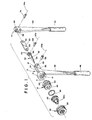
- Figure 1 illustrates the component parts of a tube expanding tool made in accordance with the present invention
- figures 2 and 3 illustrate the component parts in assembled relationship and in different relative positional relationships corresponding to stages of a tube expanding operation.
- the tool includes a body portion 10 having front and rear ends 12 and 14, respectively.
- Front end 12 of the body portion is adapted to removably receive an adapter member 16 and, for this purpose, front end 12 includes an internally threaded bore 18 and adapter 16 includes an externally threaded inner end 20 received in bore 18.
- a tool jaw assembly is removably supported on the outer end of adapter 16 and is comprised of a plurality of radially outwardly displaceable jaw elements 22 biased radially inwardly relative to one another and to axis A of the tool by means of a garter-type spring 24.
- the spring biased jaws are removably mounted on the outer end of adapter 16 by means of a cap member 26 having an internally threaded skirt portion 28 threadedly engaging externally threaded outer end 30 of adapter 16.
- Rear end 14 of body 10 includes a pair of laterally spaced apart arms 32, and the tool assembly further includes a drift or drive pin 34 coaxial with axis A and including a tapered front end 36, a cylindrical intermediate portion 38 and a pair of laterally spaced apart ears 40 at the rear end thereof.
- a drift or drive pin 34 coaxial with axis A and including a tapered front end 36, a cylindrical intermediate portion 38 and a pair of laterally spaced apart ears 40 at the rear end thereof.
- tapered end 36 engages correspondingly tapered inner surfaces 42 of jaw elements 22, and cylindrical portion 38 slidably engages in a bore 44 in adapter 16.
- Body 10 further in cludes a fixed handle 46 depending therefrom and provided on its lower end with a suitable hand grip 48, and rear end 14 of the body supports a pivotal handle 50 having a suitable hand grip 52 on the lower end thereof.
- the upper end of the handle is received between arms 32 on rear end 14 of body 10, and arms 14 are provided with aligned openings 54. Openings 54 are adapted to be aligned with an opening 56 through the upper end of handle 50, and the openings 54 and 56 receive a pin 58 by which the handle is pivotally mounted on body 10. Drift pin 34 and handle 50 are pivotally interconnected by means of a rigid link member 60 which has a front end received between ears 40 of pin 34 and provided with an opening 62. Opening 62 is aligned with openings 64 in ears 40 of pin 34, and openings 62 and 64 receive a pivot pin 66. The upper end of handle 50 is provided with a slot 68 having openings 70 in alignment with one another and with an opening 72 in the rear end of link 60 to receive a pivot pin 74.
- handle 50 is pivotal about the axis 58a of pin 58 which, for purposes of the ensuing description and in connection with the embodiment illustrated provides a first pivot axis extending transverse to and intersecting drift pin axis A.
- the axis 74a of pin 74 between link 60 and handle 50 provides a second axis parallel to the first axis, and the distance between axes 58a and 74a in effect defines a crankarm for link 60.
- the axis 66a of pin 66 between link 60 and drift pin 34 provides a third axis transverse to and intersecting drift pin axis A and, accordingly, parallel to axes 58a and 74a.
- Figures 2 and 3 respectively show handle 50 in first and second positions thereof and drift pin 34 in corresponding retracted and extended positions thereof relative to jaw elements 22 and in which the jaw elements are respectively in their radially innermost positions and outer most positions relative to axis A.
- nose portions 22a thereof are adapted to be received in the end of a tube to be expanded, and when the jaws are in their radially outermost positions the end of the tube has been expanded to the desired extent.
- the stroke of drift pin 34 between the retracted and fully extended positions thereof corresponds generally to the length of the crankarm defined by the distance between axes 58a and 74a and is achieved through a pivotal displacement of handle 50 and thus the crankarm of about 90°.
- the fixed and pivotal handles generally extend from body 10 of the tool to an extent of about twelve inches from axis A and, in accordance with the present invention, certain relationships between the pivotal handle 50, link member 60 and drift pin 34 enable tube expansion to be achieved with about the same manual force exertion by the operator as that required with the cam handle-pin type tools heretofore available and without lengthening the handles to increase the leverage, without employing multiple stroke displacement of the drift pin, and without requiring a displacement of the pivotal handle of more than about 90° relative to the tool body.
- crankarm length or distance between axes 58a and 74a which together with the location of axis 58a relative to drift pin axis A and the length of link 60 as determined by the distance between second and third axes 74a and 66a will provide the desired drift pin stroke with a maximum angle X of no more than 25° between axis A and a line B between second and third axes 74a and 66a during pivotal displacement of handle 50 between its first and second positions.
- the desired maximum angle is achieved by providing for axis 58a to intersect axis A and by providing a crankarm to link length ratio of about 1:3.25.
Landscapes
- Engineering & Computer Science (AREA)
- Mechanical Engineering (AREA)
- Hand Tools For Fitting Together And Separating, Or Other Hand Tools (AREA)
- Gripping Jigs, Holding Jigs, And Positioning Jigs (AREA)
- Shaping Of Tube Ends By Bending Or Straightening (AREA)
- Surgical Instruments (AREA)
- Details Of Spanners, Wrenches, And Screw Drivers And Accessories (AREA)
Applications Claiming Priority (2)
| Application Number | Priority Date | Filing Date | Title |
|---|---|---|---|
| US882296 | 1986-07-07 | ||
| US06/882,296 US4735078A (en) | 1986-07-07 | 1986-07-07 | Tube expanding tool |
Publications (4)
| Publication Number | Publication Date |
|---|---|
| EP0252868A2 true EP0252868A2 (fr) | 1988-01-13 |
| EP0252868A3 EP0252868A3 (en) | 1988-03-30 |
| EP0252868B1 EP0252868B1 (fr) | 1990-07-25 |
| EP0252868B2 EP0252868B2 (fr) | 1993-08-25 |
Family
ID=25380286
Family Applications (1)
| Application Number | Title | Priority Date | Filing Date |
|---|---|---|---|
| EP87630043A Expired - Lifetime EP0252868B2 (fr) | 1986-07-07 | 1987-03-30 | Outil pour élargir les tubes |
Country Status (9)
| Country | Link |
|---|---|
| US (1) | US4735078A (fr) |
| EP (1) | EP0252868B2 (fr) |
| JP (1) | JP2591953B2 (fr) |
| AU (1) | AU584292B2 (fr) |
| CA (1) | CA1252029A (fr) |
| DE (2) | DE252868T1 (fr) |
| ES (1) | ES2016649T5 (fr) |
| GR (1) | GR3000675T3 (fr) |
| NZ (1) | NZ220055A (fr) |
Cited By (11)
| Publication number | Priority date | Publication date | Assignee | Title |
|---|---|---|---|---|
| EP0309699A3 (fr) * | 1987-09-28 | 1990-03-14 | Rothenberger Werkzeuge-Maschinen Gmbh | Dispositif d'élargissement pour ebauches creuses |
| FR2645052A1 (fr) * | 1989-03-31 | 1990-10-05 | Virax Sa | Perfectionnements aux outils d'expansion se montant sur un appareil a faconner les extremites des tubes |
| EP0397570A1 (fr) * | 1989-05-12 | 1990-11-14 | Virax S.A. | Appareil destiné à élargir ou évaser les extrémités des tubes |
| DE3930710A1 (de) * | 1989-09-14 | 1991-03-28 | Rothenberger Werkzeuge Masch | Aufweitewerkzeug fuer hohle werkstuecke |
| DE4017404C1 (fr) * | 1990-05-30 | 1991-10-31 | Rothenberger Werkzeuge-Maschinen Gmbh, 6000 Frankfurt, De | |
| EP0499094A3 (en) * | 1991-02-12 | 1992-10-07 | Rothenberger Werkzeuge-Maschinen Gmbh | Expanding tool for hollow work pieces |
| FR2738512A1 (fr) * | 1995-09-07 | 1997-03-14 | Sepma Sa | Dispositif d'ecartement pour assurer l'expansion radiale d'un manchon deformable |
| WO2009000966A1 (fr) * | 2007-06-25 | 2008-12-31 | Uponor Innovation Ab | Procédé et outil pour élargir une extrémité de tuyau |
| US7922475B2 (en) | 2006-12-28 | 2011-04-12 | Virax, Société par actions simplifiée | Expansion tool device for pliers or machine for producing sockets at the ends of pipes made out of plastic or composite material |
| US9975289B2 (en) | 2016-07-27 | 2018-05-22 | Black & Decker Inc. | PEX expanding tool |
| US12558834B2 (en) | 2023-01-12 | 2026-02-24 | Black & Decker Inc. | PEX expander |
Families Citing this family (20)
| Publication number | Priority date | Publication date | Assignee | Title |
|---|---|---|---|---|
| DE3826187A1 (de) * | 1988-08-02 | 1990-02-08 | Rothenberger Werkzeuge Masch | Aufweitewerkzeug fuer hohle werkstuecke |
| US4987763A (en) * | 1989-08-24 | 1991-01-29 | O. M. S., Inc. | Tool in kit form for deforming metal |
| US5033301A (en) * | 1990-02-28 | 1991-07-23 | O.M.S., Inc. | Coupling for a gas pipe joint and associated method for making same and device therefor |
| US5138863A (en) * | 1990-03-05 | 1992-08-18 | O.M.S., Inc. | Coupling for a gas pipe joint and associated method for making same and device therefor |
| US5090230A (en) * | 1991-04-02 | 1992-02-25 | Kauno Koskinen Ky | Pipe expanding pliers |
| US5836197A (en) * | 1996-12-16 | 1998-11-17 | Mckee Machine Tool Corp. | Integral machine tool assemblies |
| US6439023B1 (en) * | 2000-03-22 | 2002-08-27 | General Electric Company | Methods and apparatus for retrofitting compressible flanges |
| ES2211842T3 (es) * | 2002-06-06 | 2004-07-16 | Rothenberger Aktiengesellschaft | Util manuel en forma de tenazas para ensanchar cuerpos huecos. |
| DE102006019405B4 (de) * | 2006-04-24 | 2011-08-18 | EADS Deutschland GmbH, 85521 | Werkzeug zur Kaltexpansion von Löchern |
| US8517715B2 (en) | 2010-04-06 | 2013-08-27 | Milwaukee Electric Tool Corporation | PEX expanding tool |
| KR101282385B1 (ko) * | 2013-02-12 | 2013-07-04 | 신이철강주식회사 | 플랜징 머신 및 그 플랜징 머신을 이용한 파이프의 플랜지 형성방법 |
| US9388885B2 (en) | 2013-03-15 | 2016-07-12 | Ideal Industries, Inc. | Multi-tool transmission and attachments for rotary tool |
| US9914260B2 (en) | 2014-06-20 | 2018-03-13 | Milwaukee Electric Tool Corporation | PEX expanding tool |
| US10000007B2 (en) | 2015-06-10 | 2018-06-19 | Milwaukee Electric Tool Corporation | PEX expanding tool |
| US9862137B2 (en) | 2015-04-20 | 2018-01-09 | Milwaukee Electric Tool Corporation | PEX expanding tool |
| US11596999B2 (en) | 2019-02-20 | 2023-03-07 | Milwaukee Electric Tool Corporation | PEX expansion tool |
| EP3698942A3 (fr) | 2019-02-20 | 2020-10-28 | Milwaukee Electric Tool Corporation | Outil d'expansion pex |
| US11110646B2 (en) | 2019-07-23 | 2021-09-07 | Brochman Innovations, Llc | PEX tubing expander head |
| CN214726466U (zh) | 2020-11-27 | 2021-11-16 | 米沃奇电动工具公司 | 扩展工具 |
| EP4319959A4 (fr) | 2021-04-09 | 2025-06-18 | Milwaukee Electric Tool Corporation | Outil d'expansion |
Family Cites Families (22)
| Publication number | Priority date | Publication date | Assignee | Title |
|---|---|---|---|---|
| DE357745C (de) * | 1922-08-31 | Herbert Mewitz | Werkzeug zum Dichten der Rohre in Vorwaermern, Kondensatoren u. dgl. | |
| US880712A (en) * | 1906-04-18 | 1908-03-03 | Wright Wire Company | Implement for applying clamps to wire fences. |
| US2277360A (en) * | 1939-01-11 | 1942-03-24 | J F Helmold & Bro | Hand press attachment |
| US2480630A (en) * | 1948-03-31 | 1949-08-30 | Young Radiator Co | Tube beading and flaring tool |
| GB693109A (en) * | 1950-01-27 | 1953-06-24 | British United Shoe Machinery | Improvements in or relating to tools adapted for use in blind riveting |
| FR1112531A (fr) * | 1954-10-12 | 1956-03-15 | Dispositif de commande pour marteaux électro-magnétiques | |
| GB866994A (en) * | 1957-11-13 | 1961-05-03 | Wlodimierz Rast | Improvements in or relating to an expanding tool for pipes |
| DE1796524U (de) * | 1959-07-14 | 1959-09-24 | August Steingass & Sohn | Aufweitungsvorrichtung. |
| US3550424A (en) * | 1968-06-12 | 1970-12-29 | Wlodzimierz Rast | Tube expander |
| US3821890A (en) * | 1972-11-29 | 1974-07-02 | H Dewey | Roof gutter and downspout and punch therefor |
| US3837211A (en) * | 1973-07-06 | 1974-09-24 | Amp Inc | Multi-stroke hand tool |
| US3841133A (en) * | 1973-08-13 | 1974-10-15 | Westinghouse Electric Corp | Apparatus and method for shaping end turns of coils in dynamo-electric machine cores |
| AU488797B1 (en) * | 1974-09-13 | 1977-03-03 | Ridge Tool Co. | Jaw construction for expanding tools |
| DE2505915A1 (de) * | 1975-02-13 | 1976-08-26 | Rothenberger Schweisstech | Vorrichtung zum aufweiten von rohrleitungsenden |
| DE2511490A1 (de) * | 1975-03-15 | 1976-09-23 | Edwin Rothenberger Schweisstec | Vorrichtung zum aufweiten von rohrleitungsenden |
| ZA763335B (en) * | 1975-06-13 | 1977-05-25 | Rast Patent Mfg Ltd | Branch tool |
| ZA763400B (en) * | 1975-06-18 | 1977-05-25 | Rast Patent Mfg Ltd | Branch tool |
| DE2552607C2 (de) * | 1975-11-24 | 1985-08-01 | Rothenberger GmbH & Co Werkzeuge-Maschinen KG, 6000 Frankfurt | Handwerkzeug zum Aufweiten von Rohrleitungsenden |
| DE2616324A1 (de) * | 1976-04-14 | 1977-10-27 | Kabel Metallwerke Ghh | Vorrichtung zum kalibrieren von rohrenden |
| DE2654102C2 (de) * | 1976-11-29 | 1984-01-05 | Rothenberger GmbH & Co Werkzeuge-Maschinen KG, 6000 Frankfurt | Expansionskopf für Rohraufweitegeräte mit auswechselbaren Expansionsbacken |
| US4237718A (en) * | 1979-05-25 | 1980-12-09 | Thomas & Betts Corporation | Bending tool |
| WO1981000364A1 (fr) * | 1979-07-30 | 1981-02-19 | Rast Patent Mfg Ltd | Outil de mandrinage de tubes |
-
1986
- 1986-07-07 US US06/882,296 patent/US4735078A/en not_active Expired - Fee Related
-
1987
- 1987-03-03 CA CA000531021A patent/CA1252029A/fr not_active Expired
- 1987-03-30 EP EP87630043A patent/EP0252868B2/fr not_active Expired - Lifetime
- 1987-03-30 DE DE198787630043T patent/DE252868T1/de active Pending
- 1987-03-30 ES ES87630043T patent/ES2016649T5/es not_active Expired - Lifetime
- 1987-03-30 DE DE8787630043T patent/DE3763923D1/de not_active Expired - Lifetime
- 1987-04-14 AU AU71781/87A patent/AU584292B2/en not_active Ceased
- 1987-04-22 NZ NZ220055A patent/NZ220055A/xx unknown
- 1987-04-30 JP JP62107926A patent/JP2591953B2/ja not_active Expired - Lifetime
-
1990
- 1990-07-27 GR GR90400376T patent/GR3000675T3/el unknown
Cited By (15)
| Publication number | Priority date | Publication date | Assignee | Title |
|---|---|---|---|---|
| EP0309699A3 (fr) * | 1987-09-28 | 1990-03-14 | Rothenberger Werkzeuge-Maschinen Gmbh | Dispositif d'élargissement pour ebauches creuses |
| FR2645052A1 (fr) * | 1989-03-31 | 1990-10-05 | Virax Sa | Perfectionnements aux outils d'expansion se montant sur un appareil a faconner les extremites des tubes |
| EP0397570A1 (fr) * | 1989-05-12 | 1990-11-14 | Virax S.A. | Appareil destiné à élargir ou évaser les extrémités des tubes |
| FR2646792A1 (fr) * | 1989-05-12 | 1990-11-16 | Virax Sa | Appareil destine a elargir ou evaser les extremites des tubes |
| DE3930710A1 (de) * | 1989-09-14 | 1991-03-28 | Rothenberger Werkzeuge Masch | Aufweitewerkzeug fuer hohle werkstuecke |
| DE4017404C1 (fr) * | 1990-05-30 | 1991-10-31 | Rothenberger Werkzeuge-Maschinen Gmbh, 6000 Frankfurt, De | |
| EP0499094A3 (en) * | 1991-02-12 | 1992-10-07 | Rothenberger Werkzeuge-Maschinen Gmbh | Expanding tool for hollow work pieces |
| US5243845A (en) * | 1991-02-12 | 1993-09-14 | Rothenberger Werkzeuge-Maschinen Gmbh | Flaring tool for hollow workpieces |
| FR2738512A1 (fr) * | 1995-09-07 | 1997-03-14 | Sepma Sa | Dispositif d'ecartement pour assurer l'expansion radiale d'un manchon deformable |
| US7922475B2 (en) | 2006-12-28 | 2011-04-12 | Virax, Société par actions simplifiée | Expansion tool device for pliers or machine for producing sockets at the ends of pipes made out of plastic or composite material |
| US8303295B2 (en) | 2006-12-28 | 2012-11-06 | Virax, Societe Par Actions Simplifiee | Expansion tool device for pliers or machine for producing sockets at the ends of pipes made out of plastic or composite material |
| WO2009000966A1 (fr) * | 2007-06-25 | 2008-12-31 | Uponor Innovation Ab | Procédé et outil pour élargir une extrémité de tuyau |
| US8562331B2 (en) | 2007-06-25 | 2013-10-22 | Uponor Innovation Ab | Method and tool for expanding a pipe end |
| US9975289B2 (en) | 2016-07-27 | 2018-05-22 | Black & Decker Inc. | PEX expanding tool |
| US12558834B2 (en) | 2023-01-12 | 2026-02-24 | Black & Decker Inc. | PEX expander |
Also Published As
| Publication number | Publication date |
|---|---|
| JP2591953B2 (ja) | 1997-03-19 |
| ES2016649B3 (es) | 1990-11-16 |
| US4735078A (en) | 1988-04-05 |
| CA1252029A (fr) | 1989-04-04 |
| EP0252868B2 (fr) | 1993-08-25 |
| DE252868T1 (de) | 1990-08-16 |
| AU584292B2 (en) | 1989-05-18 |
| EP0252868B1 (fr) | 1990-07-25 |
| GR3000675T3 (en) | 1991-09-27 |
| AU7178187A (en) | 1988-01-14 |
| EP0252868A3 (en) | 1988-03-30 |
| NZ220055A (en) | 1988-10-28 |
| ES2016649T5 (es) | 1995-08-01 |
| DE3763923D1 (de) | 1990-09-20 |
| JPS6316822A (ja) | 1988-01-23 |
Similar Documents
| Publication | Publication Date | Title |
|---|---|---|
| US4735078A (en) | Tube expanding tool | |
| US4005621A (en) | Drilling tong | |
| US3906776A (en) | Self-drilling blind riveting tool | |
| US5934139A (en) | Bi-directional impact tool | |
| DE102018105402B4 (de) | Demontagewerkzeug | |
| GB2073081A (en) | Device for driving screw pin rivet or the like | |
| EP2128381A2 (fr) | Outil de démontage d'un burin | |
| JP5121817B2 (ja) | 金属チューブの切断、または拡張に適した多目的拡張作業デバイス | |
| US4425783A (en) | Tube expanding tool | |
| EP3904005A1 (fr) | Outil de rivetage multifonctionnel | |
| EP1412116B1 (fr) | Dispositif d'echange de tetes de serrage comportant plusieurs machoires de serrage | |
| US5836197A (en) | Integral machine tool assemblies | |
| EP0512807B1 (fr) | Riveteuse avec système de dégagement des mâchoires | |
| US4703549A (en) | Double-acting pinch-free impact tool | |
| EP1980342B1 (fr) | Tête de rivetage avec système de dégagement des mâchoires | |
| DE102012223094A1 (de) | Werkzeughalter | |
| US5669730A (en) | Releasable coupling for a work tool to a percussion apparatus | |
| US4535657A (en) | Socket wrench having automatic nut-ejecting capability | |
| CN213731534U (zh) | 一种衬套拆卸工具 | |
| US20020157226A1 (en) | Device for handling retaining ring bolts | |
| EP0371162B1 (fr) | Pince de rivetage ajustable | |
| CN114434385A (zh) | 一种衬套拆卸工具及其拆卸方法 | |
| US12420364B2 (en) | Cold working tool for openings in metal pieces | |
| CN109057184B (zh) | 一种用于外墙pvc排水管的疏通结构 | |
| CN221111586U (zh) | 一种球型气动摇头万向套筒 |
Legal Events
| Date | Code | Title | Description |
|---|---|---|---|
| PUAI | Public reference made under article 153(3) epc to a published international application that has entered the european phase |
Free format text: ORIGINAL CODE: 0009012 |
|
| AK | Designated contracting states |
Kind code of ref document: A2 Designated state(s): BE CH DE ES FR GB GR IT LI NL SE |
|
| PUAL | Search report despatched |
Free format text: ORIGINAL CODE: 0009013 |
|
| AK | Designated contracting states |
Kind code of ref document: A3 Designated state(s): BE CH DE ES FR GB GR IT LI NL SE |
|
| 17P | Request for examination filed |
Effective date: 19880520 |
|
| 17Q | First examination report despatched |
Effective date: 19890712 |
|
| GRAA | (expected) grant |
Free format text: ORIGINAL CODE: 0009210 |
|
| AK | Designated contracting states |
Kind code of ref document: B1 Designated state(s): BE CH DE ES FR GB GR IT LI NL SE |
|
| ET | Fr: translation filed | ||
| DET | De: translation of patent claims | ||
| REF | Corresponds to: |
Ref document number: 3763923 Country of ref document: DE Date of ref document: 19900920 |
|
| ITF | It: translation for a ep patent filed | ||
| REG | Reference to a national code |
Ref country code: GR Ref legal event code: FG4A Free format text: 3000675 |
|
| PLBI | Opposition filed |
Free format text: ORIGINAL CODE: 0009260 |
|
| 26 | Opposition filed |
Opponent name: ROTHENBERGER WERKZEUGE-MASCHINEN GMBH Effective date: 19910416 |
|
| NLR1 | Nl: opposition has been filed with the epo |
Opponent name: ROTHENBERGER WERKZEUGE-MASCHINEN GMBH |
|
| ITTA | It: last paid annual fee | ||
| PGFP | Annual fee paid to national office [announced via postgrant information from national office to epo] |
Ref country code: CH Payment date: 19930216 Year of fee payment: 7 |
|
| PGFP | Annual fee paid to national office [announced via postgrant information from national office to epo] |
Ref country code: SE Payment date: 19930219 Year of fee payment: 7 |
|
| PGFP | Annual fee paid to national office [announced via postgrant information from national office to epo] |
Ref country code: BE Payment date: 19930223 Year of fee payment: 7 |
|
| PGFP | Annual fee paid to national office [announced via postgrant information from national office to epo] |
Ref country code: GR Payment date: 19930225 Year of fee payment: 7 |
|
| PGFP | Annual fee paid to national office [announced via postgrant information from national office to epo] |
Ref country code: NL Payment date: 19930331 Year of fee payment: 7 |
|
| PUAH | Patent maintained in amended form |
Free format text: ORIGINAL CODE: 0009272 |
|
| STAA | Information on the status of an ep patent application or granted ep patent |
Free format text: STATUS: PATENT MAINTAINED AS AMENDED |
|
| 27A | Patent maintained in amended form |
Effective date: 19930825 |
|
| AK | Designated contracting states |
Kind code of ref document: B2 Designated state(s): BE CH DE ES FR GB GR IT LI NL SE |
|
| ET3 | Fr: translation filed ** decision concerning opposition | ||
| REG | Reference to a national code |
Ref country code: CH Ref legal event code: AEN |
|
| NLR2 | Nl: decision of opposition | ||
| NLR3 | Nl: receipt of modified translations in the netherlands language after an opposition procedure | ||
| ITF | It: translation for a ep patent filed | ||
| REG | Reference to a national code |
Ref country code: GR Ref legal event code: FG4A Free format text: 3009758 |
|
| PG25 | Lapsed in a contracting state [announced via postgrant information from national office to epo] |
Ref country code: SE Free format text: LAPSE BECAUSE OF NON-PAYMENT OF DUE FEES Effective date: 19940331 Ref country code: LI Effective date: 19940331 Ref country code: CH Effective date: 19940331 Ref country code: BE Effective date: 19940331 |
|
| BERE | Be: lapsed |
Owner name: EMERSON ELECTRIC CO. Effective date: 19940331 |
|
| PG25 | Lapsed in a contracting state [announced via postgrant information from national office to epo] |
Ref country code: GR Free format text: THE PATENT HAS BEEN ANNULLED BY A DECISION OF A NATIONAL AUTHORITY Effective date: 19940930 |
|
| PG25 | Lapsed in a contracting state [announced via postgrant information from national office to epo] |
Ref country code: NL Effective date: 19941001 |
|
| NLV4 | Nl: lapsed or anulled due to non-payment of the annual fee | ||
| REG | Reference to a national code |
Ref country code: CH Ref legal event code: PL |
|
| EUG | Se: european patent has lapsed |
Ref document number: 87630043.5 Effective date: 19941010 |
|
| REG | Reference to a national code |
Ref country code: GR Ref legal event code: MM2A Free format text: 3009758 |
|
| PGFP | Annual fee paid to national office [announced via postgrant information from national office to epo] |
Ref country code: ES Payment date: 19950306 Year of fee payment: 9 |
|
| REG | Reference to a national code |
Ref country code: ES Ref legal event code: DC2A Kind code of ref document: T5 Effective date: 19950801 |
|
| PGFP | Annual fee paid to national office [announced via postgrant information from national office to epo] |
Ref country code: FR Payment date: 19960208 Year of fee payment: 10 |
|
| PGFP | Annual fee paid to national office [announced via postgrant information from national office to epo] |
Ref country code: GB Payment date: 19960216 Year of fee payment: 10 |
|
| PGFP | Annual fee paid to national office [announced via postgrant information from national office to epo] |
Ref country code: DE Payment date: 19960227 Year of fee payment: 10 |
|
| PG25 | Lapsed in a contracting state [announced via postgrant information from national office to epo] |
Ref country code: GB Effective date: 19970330 |
|
| PG25 | Lapsed in a contracting state [announced via postgrant information from national office to epo] |
Ref country code: ES Free format text: LAPSE BECAUSE OF NON-PAYMENT OF DUE FEES Effective date: 19970331 |
|
| GBPC | Gb: european patent ceased through non-payment of renewal fee |
Effective date: 19970330 |
|
| PG25 | Lapsed in a contracting state [announced via postgrant information from national office to epo] |
Ref country code: FR Free format text: LAPSE BECAUSE OF NON-PAYMENT OF DUE FEES Effective date: 19971128 |
|
| PG25 | Lapsed in a contracting state [announced via postgrant information from national office to epo] |
Ref country code: DE Effective date: 19971202 |
|
| REG | Reference to a national code |
Ref country code: FR Ref legal event code: ST |
|
| REG | Reference to a national code |
Ref country code: ES Ref legal event code: FD2A Effective date: 19990201 |
|
| PG25 | Lapsed in a contracting state [announced via postgrant information from national office to epo] |
Ref country code: IT Free format text: LAPSE BECAUSE OF NON-PAYMENT OF DUE FEES;WARNING: LAPSES OF ITALIAN PATENTS WITH EFFECTIVE DATE BEFORE 2007 MAY HAVE OCCURRED AT ANY TIME BEFORE 2007. THE CORRECT EFFECTIVE DATE MAY BE DIFFERENT FROM THE ONE RECORDED. Effective date: 20050330 |